turn signal BMW 535I GRAN TURISMO 2012 Owners Manual
[x] Cancel search | Manufacturer: BMW, Model Year: 2012, Model line: 535I GRAN TURISMO, Model: BMW 535I GRAN TURISMO 2012Pages: 321, PDF Size: 12.7 MB
Page 13 of 321
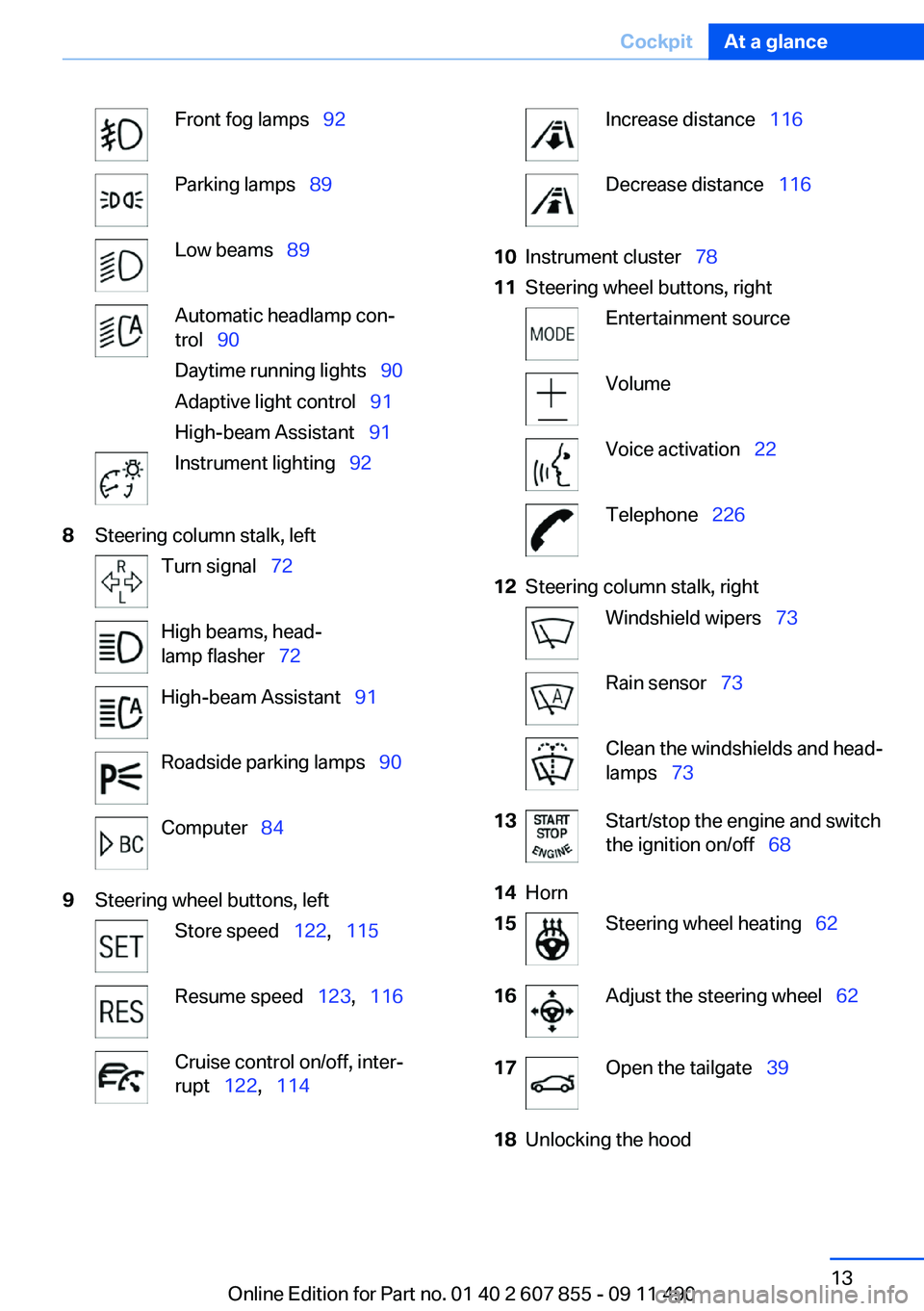
Front fog lamps 92Parking lamps 89Low beams 89Automatic headlamp con‐
trol 90
Daytime running lights 90
Adaptive light control 91
High-beam Assistant 91Instrument lighting 928Steering column stalk, leftTurn signal 72High beams, head‐
lamp flasher 72High-beam Assistant 91Roadside parking lamps 90Computer 849Steering wheel buttons, leftStore speed 122, 115Resume speed 123, 116Cruise control on/off, inter‐
rupt 122, 114Increase distance 116Decrease distance 11610Instrument cluster 7811Steering wheel buttons, rightEntertainment sourceVolumeVoice activation 22Telephone 22612Steering column stalk, rightWindshield wipers 73Rain sensor 73Clean the windshields and head‐
lamps 7313Start/stop the engine and switch
the ignition on/off 6814Horn15Steering wheel heating 6216Adjust the steering wheel 6217Open the tailgate 3918Unlocking the hoodSeite 13CockpitAt a glance13
Online Edition for Part no. 01 40 2 607 855 - 09 11 490
Page 33 of 321
4.Open "Guest".5.Create the settings.
Note: the guest profile cannot be renamed.
Display profile list during start
The profile list can be displayed during each
start for selecting the desired profile.
1."Settings"2."Profiles"3."Options" Open.4."Display user list at startup"
Personal Profile settings
The following functions and settings can be
stored in a profile.
More information on the settings can be found
under:
▷Active Cruise Control: collision warning, re‐
fer to page 120.▷Exterior mirror position, refer to page 60.▷CD/Multimedia, refer to page 196: audio
source listened to last.▷Dynamic Driving Control: sport program, re‐
fer to page 112.▷Driver's seat position, refer to page 35: au‐
tomatic retrieval after unlocking.▷Programmable memory buttons, refer to
page 20: assignment.▷Head-up Display, refer to page 134: selec‐
tion, brightness and position of the display.▷Headlamp courtesy delay feature, refer to
page 90: time setting.▷Tone, refer to page 186: tone settings.▷Automatic climate control, refer to
page 136: settings.▷Steering wheel position, refer to page 62.▷Navigation, refer to page 168: map views,
route criteria, voice output on/off.▷Night Vision with pedestrian detection, refer
to page 131: selection of functions and type
of display.▷Daytime running lights, refer to page 90:
current setting.▷Park Distance Control PDC, refer to
page 187: adjusting the signal tone volume.▷Radio, refer to page 188: stored stations,
station listened to last, special settings.▷Backup camera, refer to page 127: selec‐
tion of functions and type of display.▷Side View, refer to page 130: selection of
the display type.▷Language on the Control Display, refer to
page 87.▷Lane departure warning, refer to page 102:
last setting, on/off.▷Active Blind Spot Detection, refer to
page 104: last setting, on/off.▷Triple turn signal activation, refer to
page 72.▷Locking the vehicle, refer to page 37: after
a brief period or after starting to drive.
Central locking system
The concept
The central locking system becomes active
when the driver's door is closed.
The system simultaneously engages and re‐
leases the locks on the following:
▷Doors.▷Tailgate.▷Fuel filler flap.
Operating from the outside
▷Via the remote control.▷Via the driver's door lock.▷Via the door handles.▷Via the button on the tailgate.Seite 33Opening and closingControls33
Online Edition for Part no. 01 40 2 607 855 - 09 11 490
Page 72 of 321
Driving
Automatic Hold is activated: the vehicle is auto‐
matically secured against rolling when it stops.
The indicator lamp lights up in green.
Step on the accelerator pedal to drive
off.
The brake is released automatically.
The indicator lamp goes out.
Lower lamp: indicator lamp in Canadian models
Before driving into a car wash
Deactivate Automatic Hold; otherwise, the
parking brake will be set when the vehicle is sta‐
tionary and the vehicle will no longer be able to
roll.◀
Parking
The parking brake is automatically set if the en‐
gine is switched off while the vehicle is being
held by Automatic Hold.
The indicator lamp changes from green
to red.
The parking brake is not set if the engine
is switched off while the vehicle is coast‐
ing to a halt. Automatic Hold is deacti‐
vated.
Lower lamp: indicator lamp in Canadian models
Automatic Hold remains activated during an en‐
gine stop brought about by the Automatic En‐
gine Start/Stop Function.
Take the remote control with you
Take the remote control with you when
leaving the vehicle so that children, for example,
cannot release the parking brake.◀
Malfunction
In the event of a failure or malfunction of the
parking brake, secure the vehicle against rolling
using a wheel chock, for example, when leaving
it.Turn signal, high beams,
headlamp flasher
Turn signal
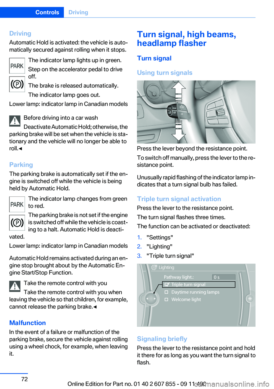
Using turn signals
Press the lever beyond the resistance point.
To switch off manually, press the lever to the re‐
sistance point.
Unusually rapid flashing of the indicator lamp in‐
dicates that a turn signal bulb has failed.
Triple turn signal activation
Press the lever to the resistance point.
The turn signal flashes three times.
The function can be activated or deactivated:
1."Settings"2."Lighting"3."Triple turn signal"
Signaling briefly
Press the lever to the resistance point and hold
it there for as long as you want the turn signal to
flash.
Seite 72ControlsDriving72
Online Edition for Part no. 01 40 2 607 855 - 09 11 490
Page 80 of 321
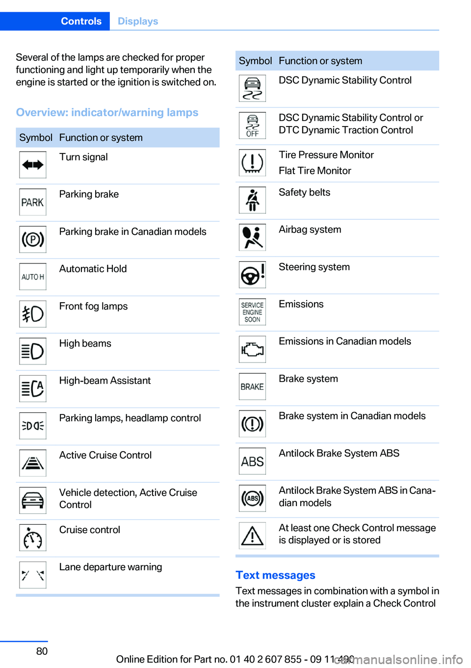
Several of the lamps are checked for proper
functioning and light up temporarily when the
engine is started or the ignition is switched on.
Overview: indicator/warning lampsSymbolFunction or systemTurn signalParking brakeParking brake in Canadian modelsAutomatic HoldFront fog lampsHigh beamsHigh-beam AssistantParking lamps, headlamp controlActive Cruise ControlVehicle detection, Active Cruise
ControlCruise controlLane departure warningSymbolFunction or systemDSC Dynamic Stability ControlDSC Dynamic Stability Control or
DTC Dynamic Traction ControlTire Pressure Monitor
Flat Tire MonitorSafety beltsAirbag systemSteering systemEmissionsEmissions in Canadian modelsBrake systemBrake system in Canadian modelsAntilock Brake System ABSAntilock Brake System ABS in Cana‐
dian modelsAt least one Check Control message
is displayed or is stored
Text messages
Text messages in combination with a symbol in
the instrument cluster explain a Check Control
Seite 80ControlsDisplays80
Online Edition for Part no. 01 40 2 607 855 - 09 11 490
Page 81 of 321
message and the meaning of the indicator and
warning lamps.
Supplementary text messages
Addition information, such as on the cause of a
fault or the required action, can be called up via
Check Control.
The supplementary text of urgent messages is
displayed on the Control Display automatically.
Symbols
Depending on the Check Control message, the
following functions can be selected.▷ "Owner's Manual"
Display additional information about the
Check Control message in the integrated
owner's manual.▷ "Service request"
Contact the service partner.▷ "Roadside Assistance"
Contact Roadside Assistance.
Hiding Check Control messages
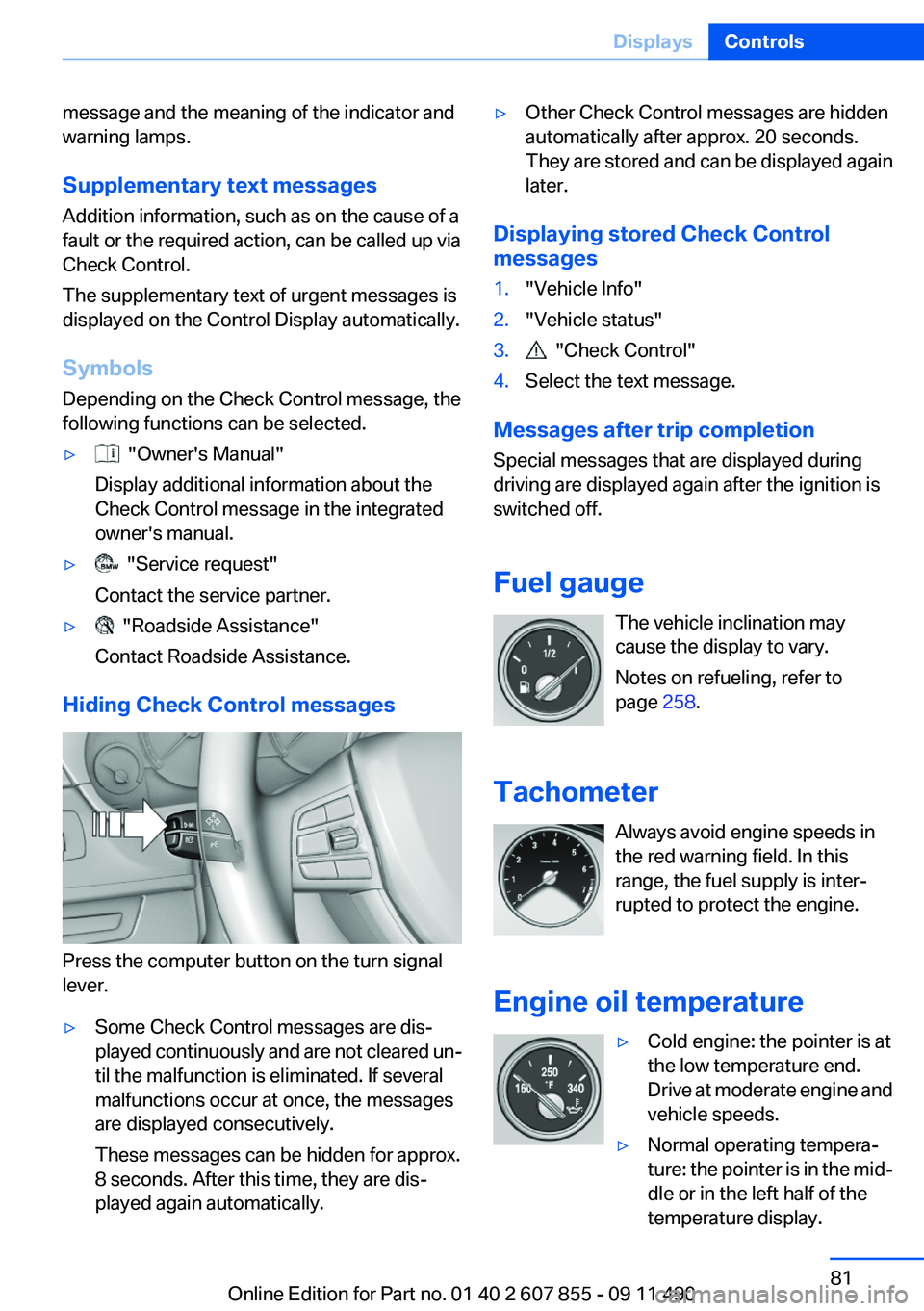
Press the computer button on the turn signal
lever.
▷Some Check Control messages are dis‐
played continuously and are not cleared un‐
til the malfunction is eliminated. If several
malfunctions occur at once, the messages
are displayed consecutively.
These messages can be hidden for approx.
8 seconds. After this time, they are dis‐
played again automatically.▷Other Check Control messages are hidden
automatically after approx. 20 seconds.
They are stored and can be displayed again
later.
Displaying stored Check Control
messages
1."Vehicle Info"2."Vehicle status"3. "Check Control"4.Select the text message.
Messages after trip completion
Special messages that are displayed during
driving are displayed again after the ignition is
switched off.
Fuel gauge The vehicle inclination may
cause the display to vary.
Notes on refueling, refer to
page 258.
Tachometer Always avoid engine speeds in
the red warning field. In this
range, the fuel supply is inter‐
rupted to protect the engine.
Engine oil temperature
▷Cold engine: the pointer is at
the low temperature end.
Drive at moderate engine and
vehicle speeds.▷Normal operating tempera‐
ture: the pointer is in the mid‐
dle or in the left half of the
temperature display.Seite 81DisplaysControls81
Online Edition for Part no. 01 40 2 607 855 - 09 11 490
Page 84 of 321
4."§ Vehicle inspection"5."Date:"6.Create the settings.7.Confirm.
The entered date is stored.
Automatic Service Request
Data regarding the maintenance status or legally
mandated inspections of the vehicle are auto‐
matically transmitted to your service center be‐
fore a service due date.
You can check when your service center was
notified.
1."Vehicle Info"2."Vehicle status"3.Open "Options".4."Last Service Request"
Selection lists in the
instrument cluster
The concept
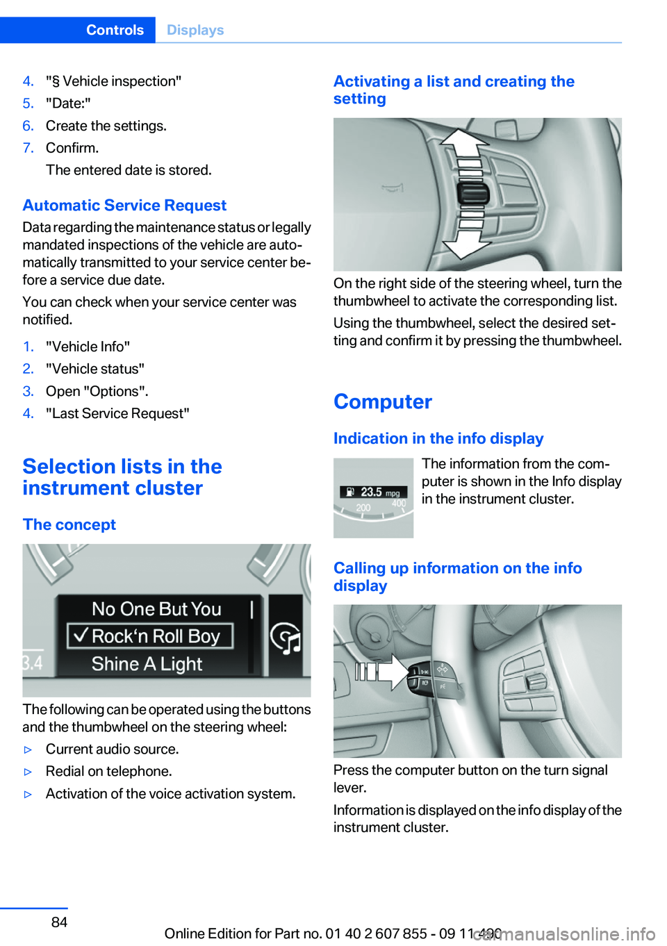
The following can be operated using the buttons
and the thumbwheel on the steering wheel:
▷Current audio source.▷Redial on telephone.▷Activation of the voice activation system.Activating a list and creating the
setting
On the right side of the steering wheel, turn the
thumbwheel to activate the corresponding list.
Using the thumbwheel, select the desired set‐
ting and confirm it by pressing the thumbwheel.
Computer
Indication in the info display The information from the com‐
puter is shown in the Info display
in the instrument cluster.
Calling up information on the info
display
Press the computer button on the turn signal
lever.
Information is displayed on the info display of the
instrument cluster.
Seite 84ControlsDisplays84
Online Edition for Part no. 01 40 2 607 855 - 09 11 490
Page 85 of 321
Information at a glance
Repeatedly pressing the button on the turn sig‐
nal lever calls up the following information on the
info display:▷Range.▷Average fuel consumption.▷Average speed.▷Date.▷Time of arrival
When destination guidance is activated in
the navigation system.▷Distance to destination
When destination guidance is activated in
the navigation system.▷Arrow view of navigation system
When destination guidance is activated in
the navigation system.
Adjusting the info display
You can select what information from the com‐
puter is to be displayed on the info display of the
instrument cluster.
1."Settings"2."Info display"3.Select the desired displays.
Information in detail
Range
Displays the estimated cruising range available
with the remaining fuel.
It is calculated based on your driving style over
the last 20 miles/30 km. If there is only enough
fuel left for less than 45 miles/80 km, the color
of the display changes.
Average fuel consumption
This is calculated for the period during which the
engine is running.
The average fuel consumption is calculated on
the basis of various distances.
Average speed
Periods in which the vehicle is parked with the
engine manually stopped do not enter into the
calculation of the average speed.
Resetting average values
Press and hold the computer button on the turn
signal lever.
Distance to destination
The distance remaining to the destination is dis‐
played if a destination is entered in the naviga‐
tion system before the trip is started.
The distance to the destination is adopted au‐
tomatically.
Time of arrival The estimated time of arrival is
displayed if a destination is en‐
tered in the navigation system
before the trip is started.
The time must be correctly set.
Speed limit
Display of a speed limit which, when reached,
should cause a warning to be issued.
Renewed warning if the vehicle speed drops be‐
low the set speed limit once by at least 3 mph/
5 km/h.
Displaying, setting or changing the
limit1."Settings"2."Speed"Seite 85DisplaysControls85
Online Edition for Part no. 01 40 2 607 855 - 09 11 490
Page 91 of 321
Adaptive light control
The concept
Adaptive light control is a variable headlamp
control system that enables dynamic illumina‐
tion of the road surface.
Depending on the steering angle and other pa‐
rameters, the light from the headlamp follows
the course of the road.
In tight curves, e.g., on mountainous roads or
when turning, an additional, corner-illuminating
lamp is switched on that lights up the inside of
the curve when the vehicle is moving below a
certain speed.
Activating
Switch position
with the ignition switched
on.
The turning lamps are automatically switched
on depending on the steering angle or the use
of turn signals.
To avoid blinding oncoming traffic, the Adaptive
Light Control directs light towards the front pas‐
senger side when the vehicle is at a standstill.
When driving in reverse, only the turning lamp is
active.
Self-leveling headlights
The self-leveling headlights feature adapts the
light distribution to the contours of the road.
The light distribution is lowered on hilltops to
avoid blinding oncoming traffic and tilted in de‐
pressions to increase visibility.
Malfunction
A Check Control message is displayed.
Adaptive light control is malfunctioning or has
failed. Have the system checked as soon as pos‐
sible.
High-beam Assistant
The concept
When the low beams are switched on, this sys‐
tem automatically switches the high beams on
and off. The procedure is controlled by a sensor
on the front of the interior rearview mirror. The
assistant ensures that the high beams are
switched on whenever the traffic situation al‐
lows. The driver can intervene at any time and
switch the high beams on and off as usual.
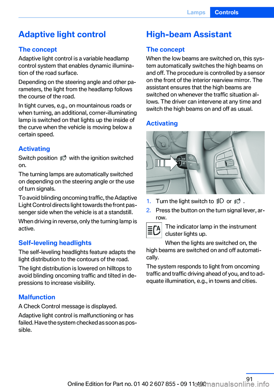
Activating1.Turn the light switch to or .2.Press the button on the turn signal lever, ar‐
row.
The indicator lamp in the instrument
cluster lights up.
When the lights are switched on, the
high beams are switched on and off automati‐
cally.
The system responds to light from oncoming
traffic and traffic driving ahead of you, and to ad‐
equate illumination, e.g., in towns and cities.
Seite 91LampsControls91
Online Edition for Part no. 01 40 2 607 855 - 09 11 490
Page 92 of 321
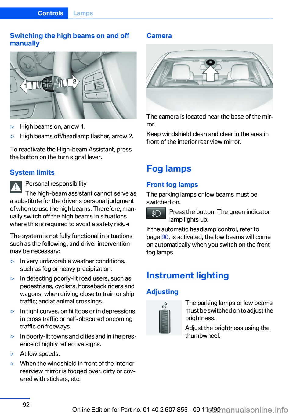
Switching the high beams on and off
manually▷High beams on, arrow 1.▷High beams off/headlamp flasher, arrow 2.
To reactivate the High-beam Assistant, press
the button on the turn signal lever.
System limits Personal responsibility
The high-beam assistant cannot serve as
a substitute for the driver's personal judgment
of when to use the high beams. Therefore, man‐
ually switch off the high beams in situations
where this is required to avoid a safety risk.◀
The system is not fully functional in situations
such as the following, and driver intervention
may be necessary:
▷In very unfavorable weather conditions,
such as fog or heavy precipitation.▷In detecting poorly-lit road users, such as
pedestrians, cyclists, horseback riders and
wagons; when driving close to train or ship
traffic; and at animal crossings.▷In tight curves, on hilltops or in depressions,
in cross traffic or half-obscured oncoming
traffic on freeways.▷In poorly-lit towns and cities and in the pres‐
ence of highly reflective signs.▷At low speeds.▷When the windshield in front of the interior
rearview mirror is fogged over, dirty or cov‐
ered with stickers, etc.Camera
The camera is located near the base of the mir‐
ror.
Keep windshield clean and clear in the area in
front of the interior rear view mirror.
Fog lamps
Front fog lamps
The parking lamps or low beams must be
switched on.
Press the button. The green indicator
lamp lights up.
If the automatic headlamp control, refer to
page 90, is activated, the low beams will come
on automatically when you switch on the front
fog lamps.
Instrument lighting
Adjusting The parking lamps or low beams
must be switched on to adjust the
brightness.
Adjust the brightness using the
thumbwheel.
Seite 92ControlsLamps92
Online Edition for Part no. 01 40 2 607 855 - 09 11 490
Page 102 of 321
Do this by checking the air pressure in all
four tires.
If the tire inflation pressure in all four tires is
correct, the Flat Tire Monitor may not have
been initialized. In this case, initialize the
system.
If an identification is not possible, please
contact the service center.2.Rectify the flat tire.
Run-flat tires
Maximum speed
You can continue driving with a damaged tire at
speeds up to 50 mph/80 km/h.
Continued driving with a flat tire
If continuing to drive with a damaged tire:
1.Avoid sudden braking and steering maneu‐
vers.2.Do not exceed a speed of 50 mph/80 km/h.3.Check the air pressure in all four tires at the
next opportunity.
If the tire inflation pressure in all four tires is
correct, the Flat Tire Monitor may not have
been initialized. In this case, initialize the
system.
Possible driving distance with complete loss of
tire inflation pressure:
The possible driving distance after a loss of tire
inflation pressure depends on the cargo load
and the driving style and conditions.
For a vehicle containing an average load, the
possible driving distance is approx. 50 miles/
80 km.
When the vehicle is driven with a damaged tire,
its handling characteristics change, e.g., re‐
duced lane stability during braking, a longer
braking distance, and altered self-steering
properties. Adjust your driving style accord‐
ingly. Avoid abrupt steering maneuvers or driv‐
ing over obstacles, e.g., curbs, potholes, etc.
Because the possible driving distance depends
on how the vehicle is used during the trip, the
actual distance may be smaller or greater de‐
pending on the driving speed, road conditions,
external temperature, cargo load, etc.
Continued driving with a flat tire
Drive moderately and do not exceed a
speed of 50 mph/80 km/h.
A loss of tire inflation pressure results in a
change in the handling characteristics, e.g., re‐
duced lane stability during braking, a longer
braking distance and altered self-steering prop‐
erties.◀
Final tire failure
Vibrations or loud noises while driving can
indicate the final failure of the tire. Reduce speed
and stop; otherwise, pieces of the tire could
come loose and cause an accident. Do not con‐
tinue driving, and contact your service center. ◀
Lane departure warning
The concept
This system issues a warning at speeds above
approx. 40 mph/65 km/h if the vehicle is about
to leave the lane on roads with lane markings.
The steering wheel begins vibrating gently. The
time of the warning may vary depending on the
current driving situation.
The system does not provide a warning if the
turn signal is set before leaving the lane.
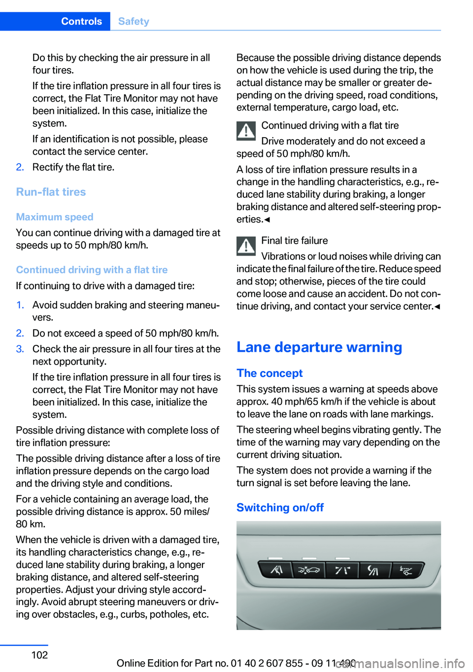
Switching on/offSeite 102ControlsSafety102
Online Edition for Part no. 01 40 2 607 855 - 09 11 490