fuel BMW 535I GRAN TURISMO 2013 Owners Manual
[x] Cancel search | Manufacturer: BMW, Model Year: 2013, Model line: 535I GRAN TURISMO, Model: BMW 535I GRAN TURISMO 2013Pages: 240, PDF Size: 5.49 MB
Page 5 of 240
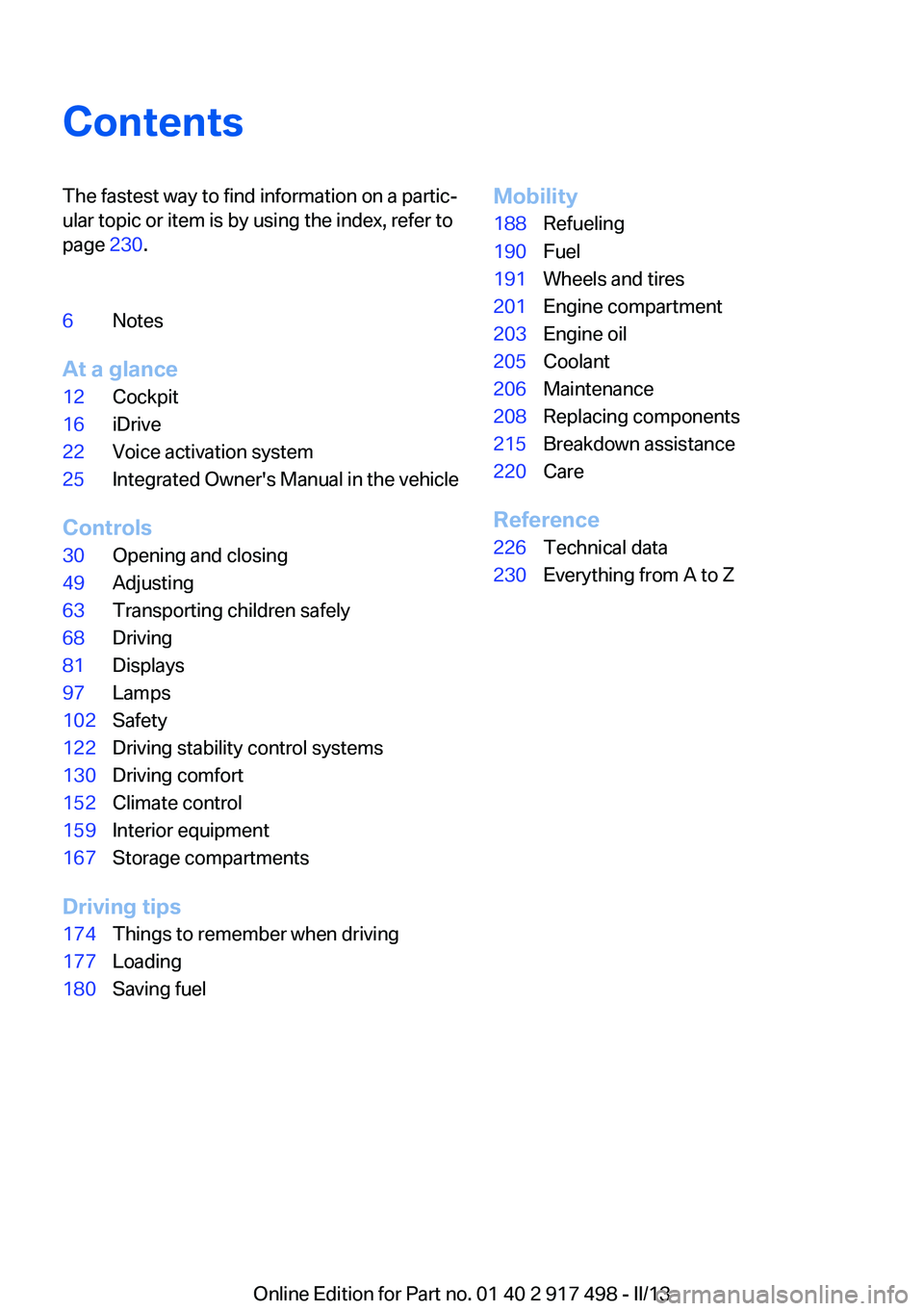
ContentsThe fastest way to find information on a partic‐
ular topic or item is by using the index, refer to
page 230.6Notes
At a glance
12Cockpit16iDrive22Voice activation system25Integrated Owner's Manual in the vehicle
Controls
30Opening and closing49Adjusting63Transporting children safely68Driving81Displays97Lamps102Safety122Driving stability control systems130Driving comfort152Climate control159Interior equipment167Storage compartments
Driving tips
174Things to remember when driving177Loading180Saving fuelMobility188Refueling190Fuel191Wheels and tires201Engine compartment203Engine oil205Coolant206Maintenance208Replacing components215Breakdown assistance220Care
Reference
226Technical data230Everything from A to Z
Online Edition for Part no. 01 40 2 917 498 - II/13
Page 34 of 240
Central locking system
The concept
The central locking system becomes active
when the driver's door is closed.
The system simultaneously engages and re‐
leases the locks on the following:▷Doors.▷Tailgate.▷Fuel filler flap.
Operating from the outside
▷Via the remote control.▷Via the driver's door lock.▷Via the door handles.▷Via the button on the tailgate.
The following takes place simultaneously when
locking/unlocking the vehicle via the remote
control:
▷Depending on how the vehicle is equipped,
the theft protection is activated/deactivated.
Theft protection prevents the doors from
being unlocked using the lock buttons or the
door opener.▷The welcome lamps, interior lamps and
courtesy lamps are switched on and off.▷The alarm system, refer to page 43, is
armed or disarmed.
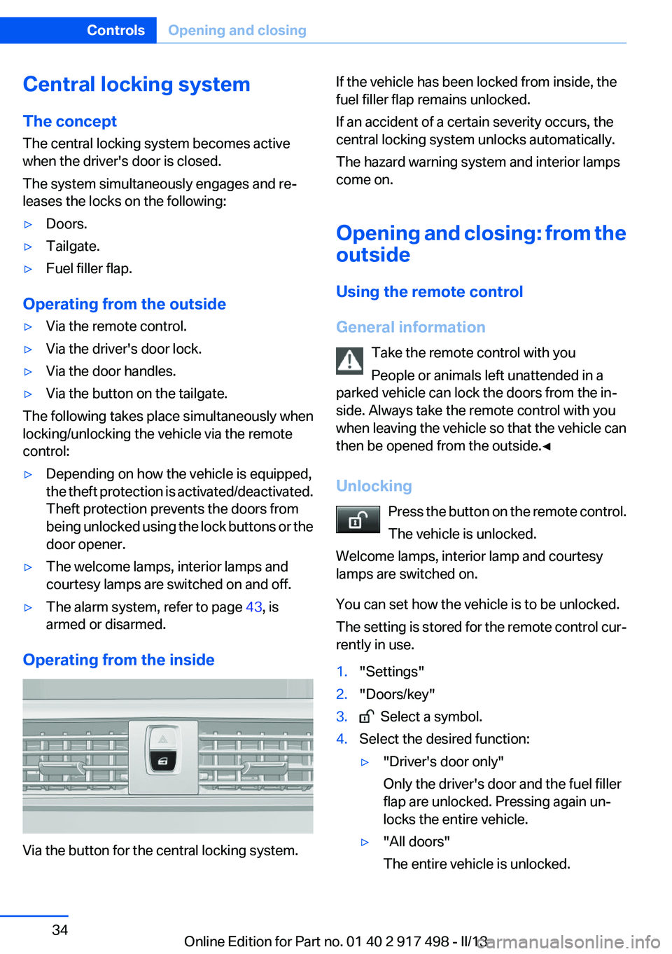
Operating from the inside
Via the button for the central locking system.
If the vehicle has been locked from inside, the
fuel filler flap remains unlocked.
If an accident of a certain severity occurs, the
central locking system unlocks automatically.
The hazard warning system and interior lamps
come on.
Opening and closing: from the
outside
Using the remote control
General information Take the remote control with you
People or animals left unattended in a
parked vehicle can lock the doors from the in‐
side. Always take the remote control with you
when leaving the vehicle so that the vehicle can
then be opened from the outside.◀
Unlocking Press the button on the remote control.
The vehicle is unlocked.
Welcome lamps, interior lamp and courtesy
lamps are switched on.
You can set how the vehicle is to be unlocked.
The setting is stored for the remote control cur‐
rently in use.1."Settings"2."Doors/key"3. Select a symbol.4.Select the desired function:▷"Driver's door only"
Only the driver's door and the fuel filler
flap are unlocked. Pressing again un‐
locks the entire vehicle.▷"All doors"
The entire vehicle is unlocked.Seite 34ControlsOpening and closing34
Online Edition for Part no. 01 40 2 917 498 - II/13
Page 37 of 240
In order to terminate this alarm, unlock vehicle
with the remote control, or switch on the igni‐
tion, if necessary, by emergency detection of the
remote control.
In some vehicle equipment versions, only the
driver's door can be unlocked or locked via the
door lock.
Locking the doors and tailgate at once
To lock all doors and the tailgate at once:1.With the doors closed, lock the vehicle using
the button for the central locking system in
the interior.2.Unlock and open the driver's or front pas‐
senger door.3.Lock the vehicle.▷Lock the driver's door using the
integrated key in the door lock, or▷Press down the lock button of the front
passenger door and close the door from
the outside.
The fuel filler flap can only be locked using the
remote control.
Manual operation
If an electrical malfunction occurs, lock or unlock
the vehicle using the integrated key via the door
lock on the driver's door.
Opening and closing: from the
inside
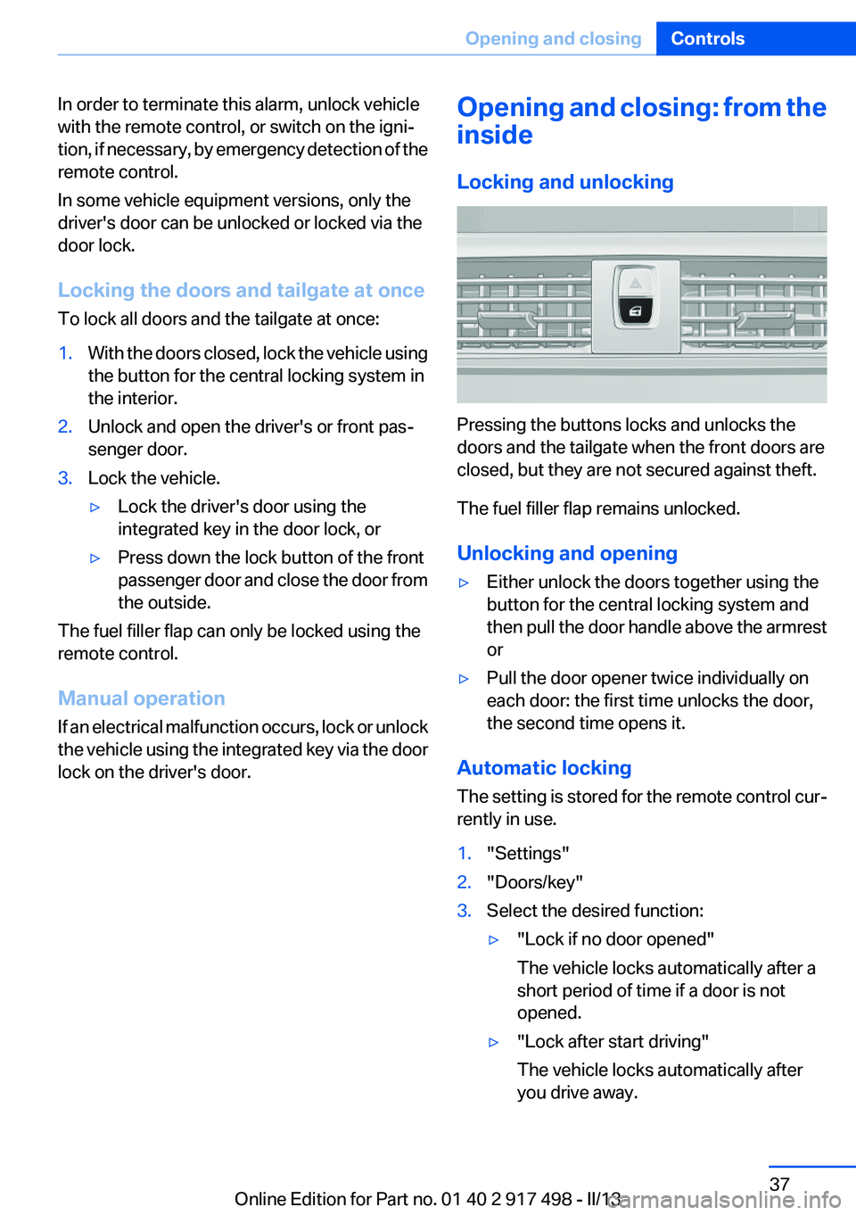
Locking and unlocking
Pressing the buttons locks and unlocks the
doors and the tailgate when the front doors are
closed, but they are not secured against theft.
The fuel filler flap remains unlocked.
Unlocking and opening
▷Either unlock the doors together using the
button for the central locking system and
then pull the door handle above the armrest
or▷Pull the door opener twice individually on
each door: the first time unlocks the door,
the second time opens it.
Automatic locking
The setting is stored for the remote control cur‐
rently in use.
1."Settings"2."Doors/key"3.Select the desired function:▷"Lock if no door opened"
The vehicle locks automatically after a
short period of time if a door is not
opened.▷"Lock after start driving"
The vehicle locks automatically after
you drive away.Seite 37Opening and closingControls37
Online Edition for Part no. 01 40 2 917 498 - II/13
Page 69 of 240
Radio ready state
Activate radio ready state:▷When the ignition is switched off: press ON/
OFF button on the radio.▷When the engine is running: press the Start/
Stop button.
Some electronic systems/power consumers re‐
main ready for operation.
Radio ready state switches off automatically:
▷After approx. 8 minutes.▷When the vehicle is locked using the central
locking system.▷Shortly before the battery is discharged
completely, so that the engine can still be
started.
Starting the engine
General information Enclosed areas
Do not let the engine run in enclosed
areas; otherwise, breathing of exhaust fumes
may lead to loss of consciousness and death.
The exhaust gases contain carbon monoxide, an
odorless and colorless but highly toxic gas.◀
Unattended vehicle
Do not leave the vehicle unattended with
the engine running; doing so poses a risk of dan‐
ger.
Before leaving the vehicle with the engine run‐
ning, set the parking brake and place the trans‐
mission in position P or neutral to prevent the
vehicle from moving.◀
Repeated starting in quick succession
Avoid repeated unsuccessful attempts to
start the vehicle or starting the vehicle several
times in quick succession. Otherwise, the fuel is
not burned or is inadequately burned, posing a
risk of overheating and damage to the catalytic
converter.◀
Do not wait for the engine to warm up while the
vehicle remains stationary. Start driving at mod‐
erate engine speeds.
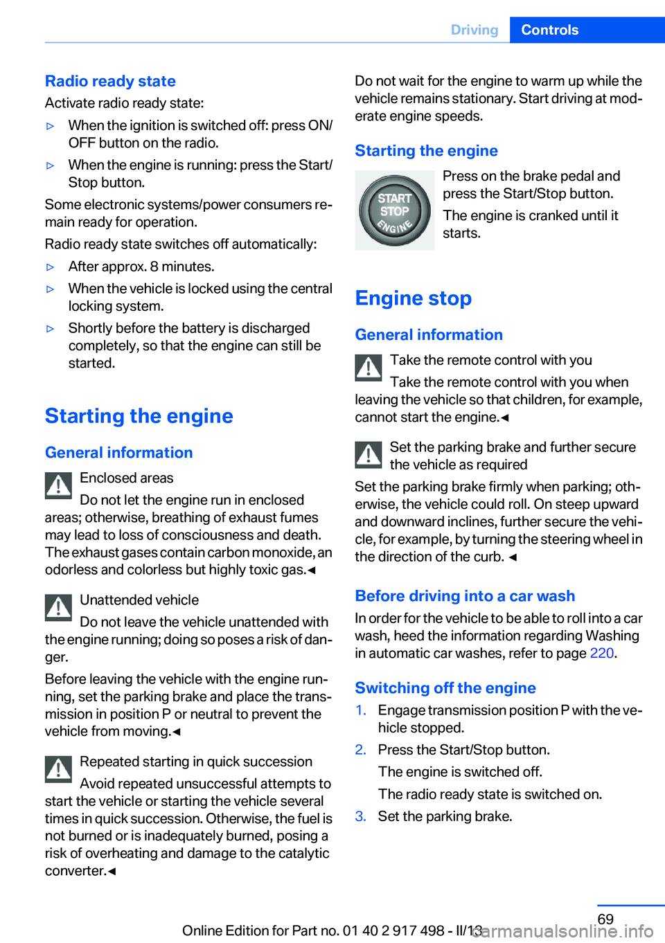
Starting the engine Press on the brake pedal and
press the Start/Stop button.
The engine is cranked until it
starts.
Engine stop
General information Take the remote control with you
Take the remote control with you when
leaving the vehicle so that children, for example,
cannot start the engine.◀
Set the parking brake and further secure
the vehicle as required
Set the parking brake firmly when parking; oth‐
erwise, the vehicle could roll. On steep upward
and downward inclines, further secure the vehi‐
cle, for example, by turning the steering wheel in
the direction of the curb. ◀
Before driving into a car wash
In order for the vehicle to be able to roll into a car
wash, heed the information regarding Washing
in automatic car washes, refer to page 220.
Switching off the engine1.Engage transmission position P with the ve‐
hicle stopped.2.Press the Start/Stop button.
The engine is switched off.
The radio ready state is switched on.3.Set the parking brake.Seite 69DrivingControls69
Online Edition for Part no. 01 40 2 917 498 - II/13
Page 70 of 240
Auto Start/Stop function
The concept
The Auto Start/Stop function helps save fuel.
The system switches off the engine during a
stop, e.g., in a traffic congestion or at traffic
lights. The ignition remains switched on. The
engine starts again automatically for driving off.
Certain vehicle components may experience
additional wear as a result of this system.
Automatic mode
The Auto Start/Stop function is operational after
each engine start.
This function is activated at speeds faster than
about 3 mph, approx. 5 km/h.
Engine stop
The engine is switched off automatically during
a stop under the following conditions:
Automatic transmission:▷The selector lever is in transmission position
D.▷The brake pedal remains pressed while the
vehicle is stationary or the vehicle is held by
Automatic Hold.▷The driver's safety belt is buckled or the
driver's door is closed.
The air flow of the air conditioner is reduced
when the engine is switched off.
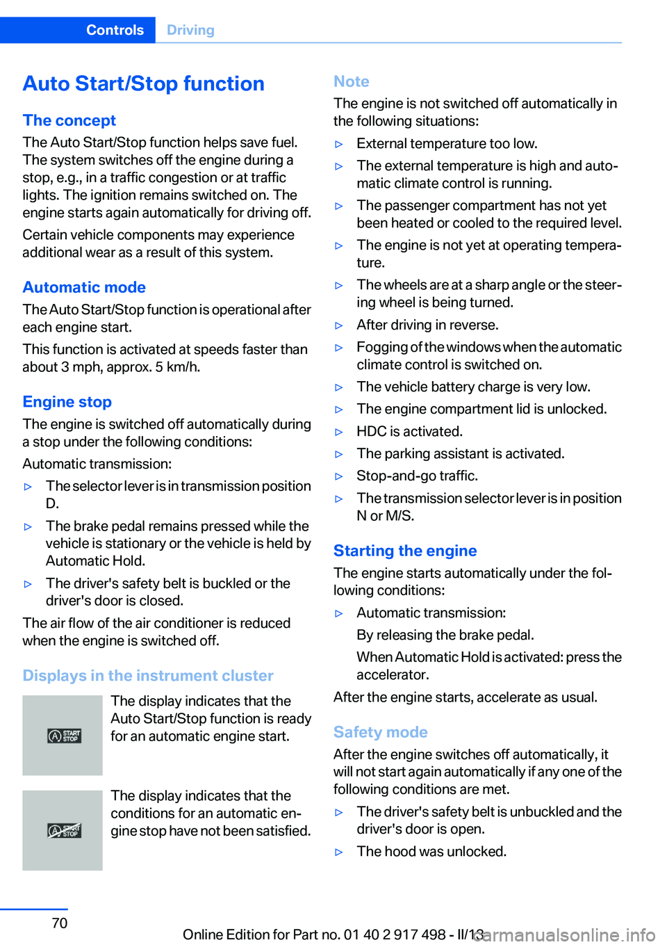
Displays in the instrument cluster The display indicates that the
Auto Start/Stop function is ready
for an automatic engine start.
The display indicates that the
conditions for an automatic en‐
gine stop have not been satisfied.
Note
The engine is not switched off automatically in
the following situations:▷External temperature too low.▷The external temperature is high and auto‐
matic climate control is running.▷The passenger compartment has not yet
been heated or cooled to the required level.▷The engine is not yet at operating tempera‐
ture.▷The wheels are at a sharp angle or the steer‐
ing wheel is being turned.▷After driving in reverse.▷Fogging of the windows when the automatic
climate control is switched on.▷The vehicle battery charge is very low.▷The engine compartment lid is unlocked.▷HDC is activated.▷The parking assistant is activated.▷Stop-and-go traffic.▷The transmission selector lever is in position
N or M/S.
Starting the engine
The engine starts automatically under the fol‐
lowing conditions:
▷Automatic transmission:
By releasing the brake pedal.
When Automatic Hold is activated: press the
accelerator.
After the engine starts, accelerate as usual.
Safety mode
After the engine switches off automatically, it
will not start again automatically if any one of the
following conditions are met.
▷The driver's safety belt is unbuckled and the
driver's door is open.▷The hood was unlocked.Seite 70ControlsDriving70
Online Edition for Part no. 01 40 2 917 498 - II/13
Page 81 of 240
DisplaysVehicle equipment
All standard, country-specific and optional
equipment that is offered in the model series is
described in this chapter. Therefore, equipmentis also described that is not available in a vehicle,
e. g., because of the selected optional equip‐
ment or country variant. This also applies for
safety-related functions and systems.
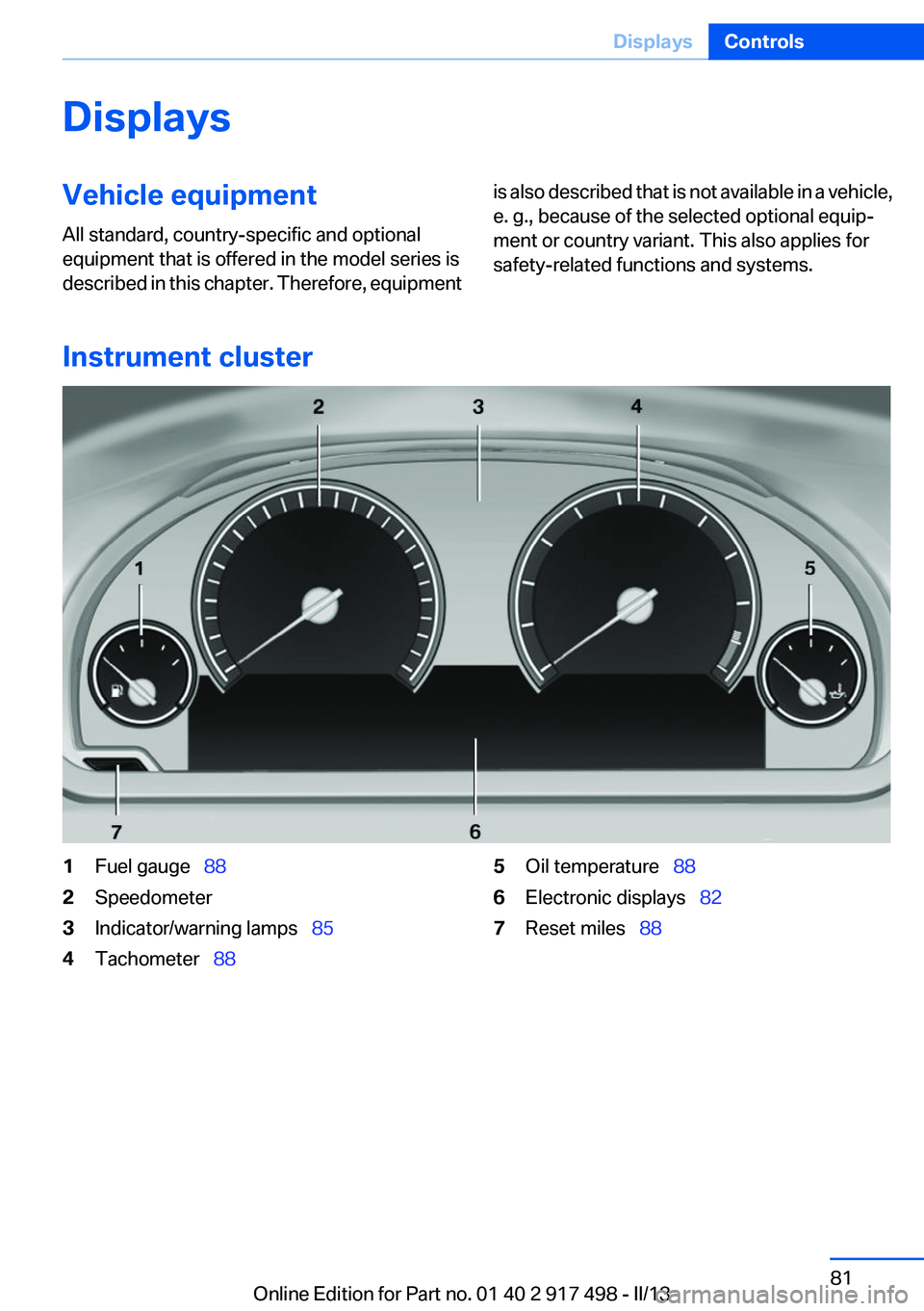
Instrument cluster
1Fuel gauge 882Speedometer3Indicator/warning lamps 854Tachometer 885Oil temperature 886Electronic displays 827Reset miles 88Seite 81DisplaysControls81
Online Edition for Part no. 01 40 2 917 498 - II/13
Page 82 of 240
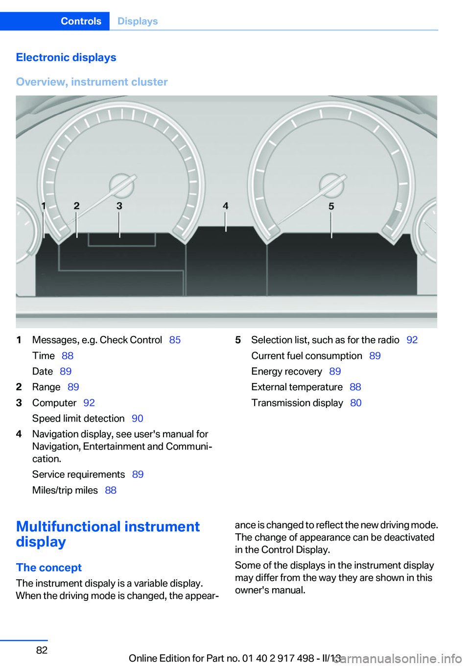
Electronic displays
Overview, instrument cluster1Messages, e.g. Check Control 85
Time 88
Date 892Range 893Computer 92
Speed limit detection 904Navigation display, see user's manual for
Navigation, Entertainment and Communi‐
cation.
Service requirements 89
Miles/trip miles 885Selection list, such as for the radio 92
Current fuel consumption 89
Energy recovery 89
External temperature 88
Transmission display 80Multifunctional instrument
display
The concept
The instrument dispaly is a variable display.
When the driving mode is changed, the appear‐ance is changed to reflect the new driving mode.
The change of appearance can be deactivated
in the Control Display.
Some of the displays in the instrument display
may differ from the way they are shown in this
owner's manual.Seite 82ControlsDisplays82
Online Edition for Part no. 01 40 2 917 498 - II/13
Page 83 of 240
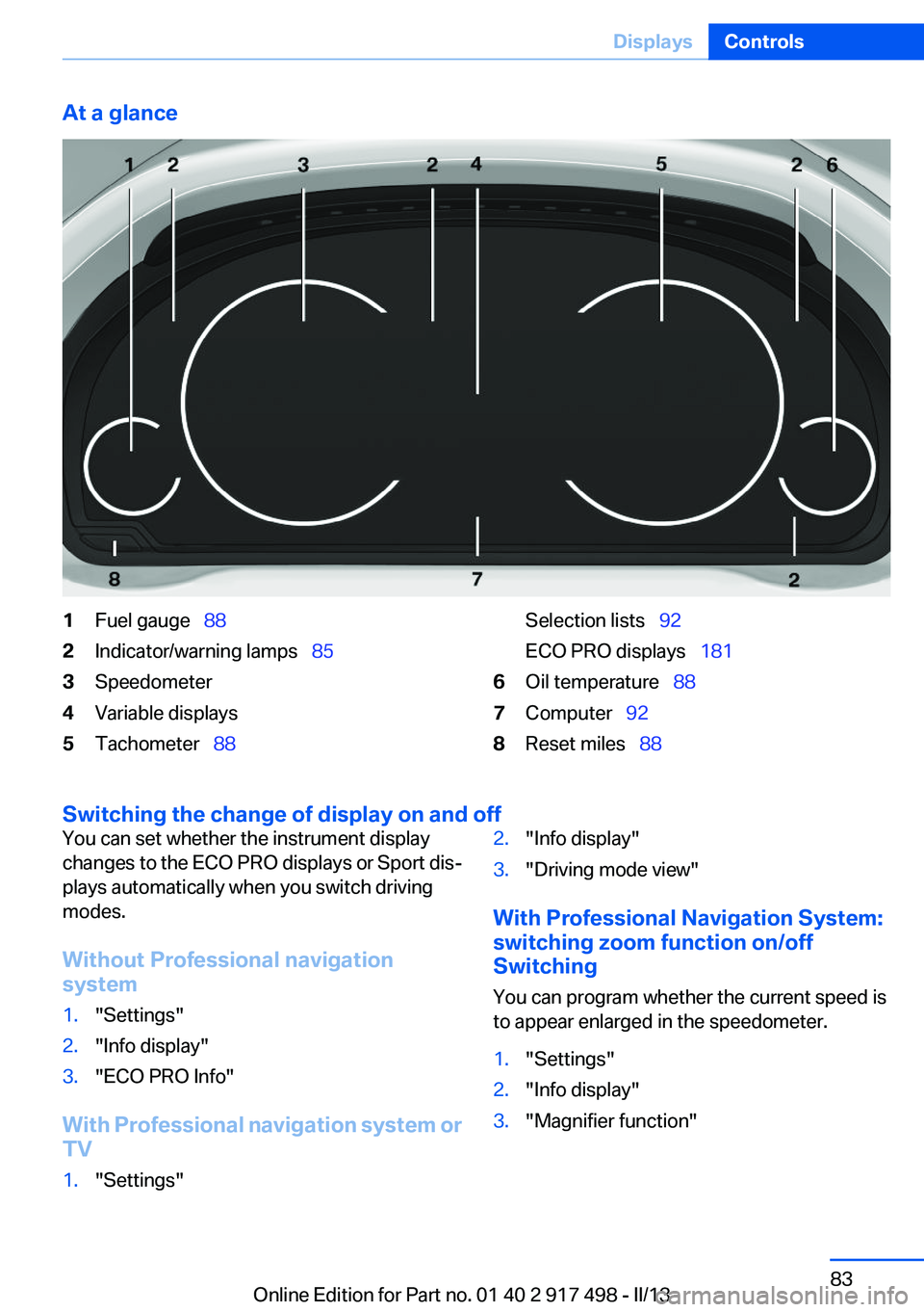
At a glance1Fuel gauge 882Indicator/warning lamps 853Speedometer4Variable displays5Tachometer 88Selection lists 92
ECO PRO displays 1816Oil temperature 887Computer 928Reset miles 88
Switching the change of display on and off
You can set whether the instrument display
changes to the ECO PRO displays or Sport dis‐
plays automatically when you switch driving
modes.
Without Professional navigation
system1."Settings"2."Info display"3."ECO PRO Info"
With Professional navigation system or
TV
1."Settings"2."Info display"3."Driving mode view"
With Professional Navigation System:
switching zoom function on/off
Switching
You can program whether the current speed is
to appear enlarged in the speedometer.
1."Settings"2."Info display"3."Magnifier function"Seite 83DisplaysControls83
Online Edition for Part no. 01 40 2 917 498 - II/13
Page 84 of 240
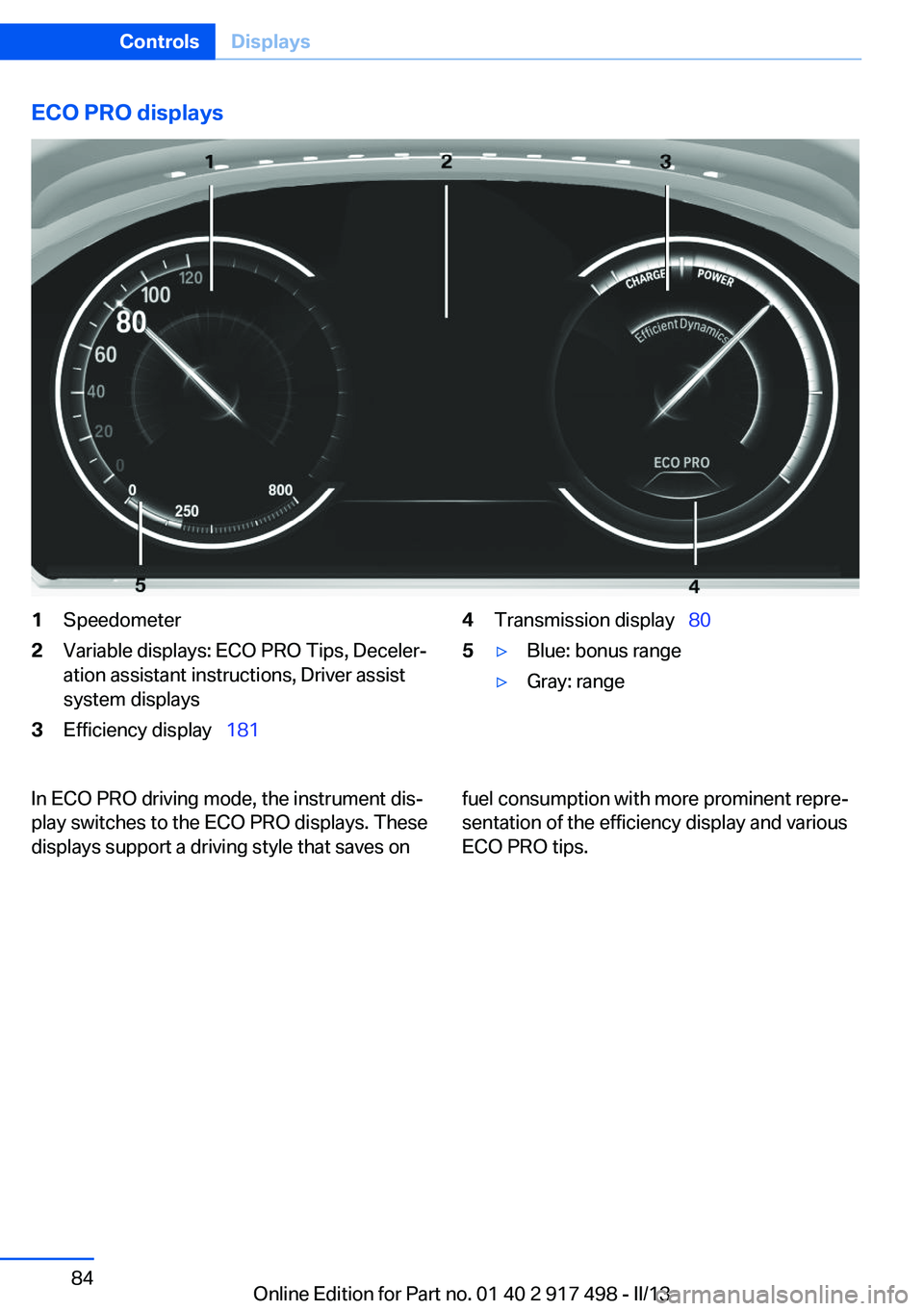
ECO PRO displays1Speedometer2Variable displays: ECO PRO Tips, Deceler‐
ation assistant instructions, Driver assist
system displays3Efficiency display 1814Transmission display 805▷Blue: bonus range▷Gray: rangeIn ECO PRO driving mode, the instrument dis‐
play switches to the ECO PRO displays. These
displays support a driving style that saves onfuel consumption with more prominent repre‐
sentation of the efficiency display and various
ECO PRO tips.Seite 84ControlsDisplays84
Online Edition for Part no. 01 40 2 917 498 - II/13
Page 88 of 240
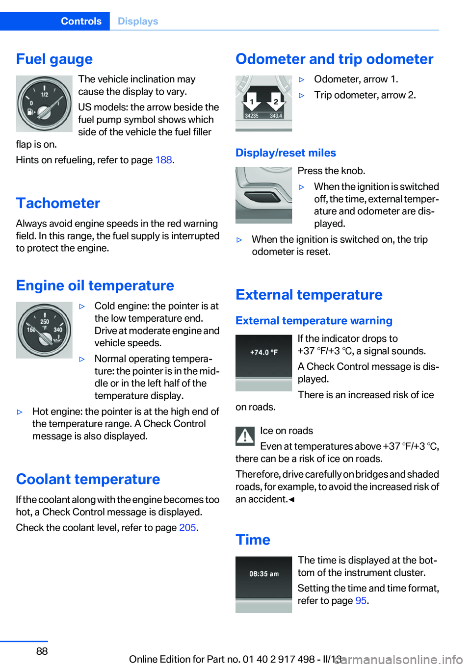
Fuel gaugeThe vehicle inclination may
cause the display to vary.
US models: the arrow beside the
fuel pump symbol shows which
side of the vehicle the fuel filler
flap is on.
Hints on refueling, refer to page 188.
Tachometer
Always avoid engine speeds in the red warning
field. In this range, the fuel supply is interrupted
to protect the engine.
Engine oil temperature▷Cold engine: the pointer is at
the low temperature end.
Drive at moderate engine and
vehicle speeds.▷Normal operating tempera‐
ture: the pointer is in the mid‐
dle or in the left half of the
temperature display.▷Hot engine: the pointer is at the high end of
the temperature range. A Check Control
message is also displayed.
Coolant temperature
If the coolant along with the engine becomes too
hot, a Check Control message is displayed.
Check the coolant level, refer to page 205.
Odometer and trip odometer▷Odometer, arrow 1.▷Trip odometer, arrow 2.
Display/reset miles
Press the knob.
▷When the ignition is switched
off, the time, external temper‐
ature and odometer are dis‐
played.▷When the ignition is switched on, the trip
odometer is reset.
External temperature
External temperature warning If the indicator drops to
+37 ℉/+3 ℃, a signal sounds.
A Check Control message is dis‐
played.
There is an increased risk of ice
on roads.
Ice on roads
Even at temperatures above +37 ℉/+3 ℃,
there can be a risk of ice on roads.
Therefore, drive carefully on bridges and shaded
roads, for example, to avoid the increased risk of
an accident.◀
Time The time is displayed at the bot‐
tom of the instrument cluster.
Setting the time and time format,
refer to page 95.
Seite 88ControlsDisplays88
Online Edition for Part no. 01 40 2 917 498 - II/13