Sport BMW 535I GT 2011 F07 Owner's Manual
[x] Cancel search | Manufacturer: BMW, Model Year: 2011, Model line: 535I GT, Model: BMW 535I GT 2011 F07Pages: 297, PDF Size: 8.59 MB
Page 5 of 297
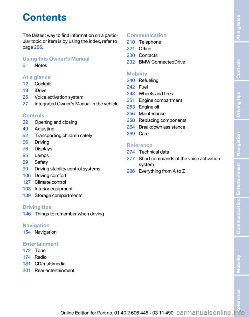
Contents
The fastest way to find information on a partic‐
ular topic or item is by using the index, refer to
page
286.
Using this Owner's Manual
6 Notes
At a glance
12 Cockpit
19 iDrive
25 Voice activation system
27 Integrated Owner's Manual in the vehicle
Controls
32 Opening and closing
49 Adjusting
62 Transporting children safely
66 Driving
76 Displays
85 Lamps
89 Safety
99 Driving stability control systems
106 Driving comfort
127 Climate control
133 Interior equipment
139 Storage compartments
Driving tips
146 Things to remember when driving
Navigation
154 Navigation
Entertainment
172 Tone
174 Radio
181 CD/multimedia
201 Rear entertainment Communication
210
Telephone
221 Office
230 Contacts
232 BMW ConnectedDrive
Mobility
240 Refueling
242 Fuel
243 Wheels and tires
251 Engine compartment
253 Engine oil
256 Maintenance
258 Replacing components
264 Breakdown assistance
269 Care
Reference
274 Technical data
277 Short commands of the voice activation
system
286 Everything from A to Z
Seite 5
Online Edition for Part no. 01 40 2 606 445 - 03 11 490 Reference Mobility Communication Entertainment Navigation Driving tips Controls At a glance
Page 8 of 297
erate your vehicle in another country or region,
you may be required to adapt your vehicle to
meet different prevailing operating conditions
and homologation requirements. You should
also be aware of any applicable warranty limita‐
tions
or exclusions for such country or region. In
such case, please contact Customer Relations
for further information.
Reporting safety defects
For US customers
The following only applies to vehicles owned
and operated in the US.
If you believe that your vehicle has a defect
which could cause a crash or could cause injury
or death, you should immediately inform the Na‐
tional Highway Traffic Safety Administration
NHTSA, in addition to notifying BMW of North
America, LLC, P.O. Box 1227, Westwood, New
Jersey 07675-1227, Telephone
1-800-831-1117.
If NHTSA receives similar complaints, it may
open an investigation, and if it finds that a safety
defect exists in a group of vehicles, it may order
a recall and remedy campaign.
However, NHTSA cannot become involved in
individual problems between you, your dealer,
or BMW of North America, LLC.
To contact NHTSA, you may call the Vehicle
Safety Hotline toll-free at 1-888-327-4236
(TTY: 1-800-424-9153); go to http://www.safe‐
rcar.gov; or write to: Administrator, NHTSA, 400
Seventh Street, SW., Washington, DC 20590.
You can also obtain other information about mo‐
tor vehicle safety from http://www.safercar.gov
For Canadian customers
Canadian customers who wish to report a
safety-related defect to Transport Canada, De‐
fect Investigations and Recalls, may telephone
the toll-free hotline 1-800-333-0510. You can
also obtain other information about motor vehi‐
cle safety from http://www.tc.gc.ca/roadsafety.
Seite 8
8 Online Edition for Part no. 01 40 2 606 445 - 03 11 490
Notes
Page 35 of 297
▷
Dynamic Driving Control: sport program, re‐
fer to page 104.
▷ Driver's seat position, refer to page 37: au‐
tomatic retrieval after unlocking.
▷ Programmable memory buttons, refer to
page 23: assignment.
▷ Head-up Display, refer to page 125: selec‐
tion, brightness and position of the display.
▷ Headlamp courtesy delay feature, refer to
page 85: time setting.
▷ Tone, refer to page 172: tone settings.
▷ Automatic climate control, refer to
page 127: settings.
▷ Steering wheel position, refer to page 61
▷ Navigation, refer to page 154: map views,
route criteria, voice output on/off.
▷ Night Vision with pedestrian detection, refer
to
page 122: selection of functions and type
of display.
▷ Daytime running lights*, refer to page 86:
current setting.
▷ Park Distance Control PDC, refer to
page 173:
adjusting the signal tone volume.
▷ Radio, refer to page 174: stored stations,
station listened to last, special settings.
▷ Backup camera, refer to page 119: selec‐
tion of functions and type of display.
▷ Side View, refer to page 121: selection of
the display type.
▷ Language on the Control Display, refer to
page 82.
▷ Lane departure warning, refer to page 95:
last setting, on/off.
▷ Active Blind Spot Detection, refer to
page 96: last setting, on/off.
▷ Triple turn signal activation, refer to
page 71.
▷ Locking the vehicle, refer to page 39: after
a brief period or after starting to drive. Central locking system
The concept
The central locking system becomes active
when the driver's door is closed.
The system simultaneously engages and re‐
leases the locks on the following:
▷
Doors.
▷ Tailgate.
▷ Fuel filler flap.
Operating from the outside
▷ Via the remote control.
▷ Via the driver's door lock*.
▷ Via the door handles*.
▷ Via the button on the tailgate*.
The following takes place simultaneously when
locking/unlocking the vehicle via the remote
control:
▷ Anti-theft protection is switched on/off.
Doors cannot be unlocked using the lock
buttons or the door opener.
▷ The welcome lamps, interior lamps and
courtesy lamps* are switched on and off.
▷ The alarm system*, refer to page 44, is
armed or disarmed.
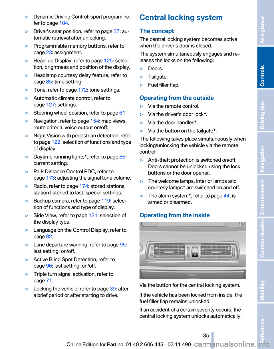
Operating from the inside Via the button for the central locking system.
If the vehicle has been locked from inside, the
fuel filler flap remains unlocked.
If an accident of a certain severity occurs, the
central locking system unlocks automatically.
Seite 35
35Online Edition for Part no. 01 40 2 606 445 - 03 11 490
Reference Mobility Communication Entertainment Navigation Driving tips
Controls At a glance
Page 45 of 297
▷
The indicator lamp flashes after unlocking
until
the engine is started, but no longer than
approx. 5 minutes:
An alarm has been triggered.
Tilt alarm sensor
The tilt of the vehicle is monitored.
The alarm system responds in situations such
as attempts to steal a wheel or tow the car.
Interior motion sensor
The
windows and glass sunroof* must be closed
for the system to function properly.
Avoiding unintentional alarms
The tilt alarm sensor and interior motion sensor
can be switched off together, such as in the fol‐
lowing situations:
▷ In automatic car washes
▷ In duplex garages.
▷ During transport on car-carrying trains, at
sea or on a trailer.
▷ When animals are to remain in the vehicle.
Switching off the tilt alarm sensor and
interior motion sensor Press the button on the remote control
twice in succession.
The indicator lamp lights up for approx. 2 sec‐
onds and then flashes continuously.
The
tilt alarm sensor and interior motion sensor
are switched off until the vehicle is locked again.
Power windows
General information
Take the remote control with you
Take the remote control with you when
leaving the vehicle so that children, for example,
cannot operate the power windows and injure
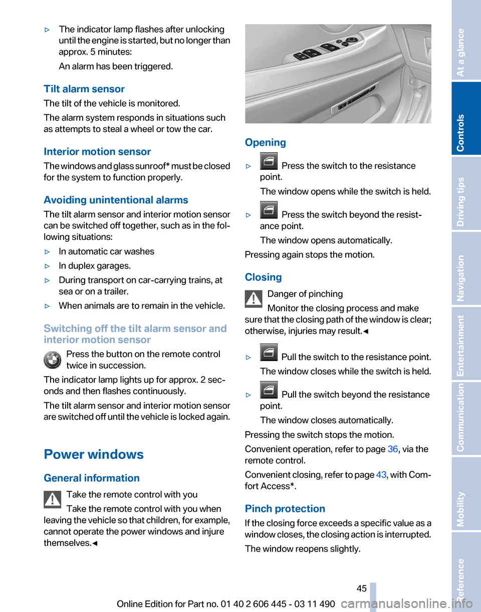
themselves.◀ Opening
▷
Press the switch to the resistance
point.
The window opens while the switch is held.
▷ Press the switch beyond the resist‐
ance point.
The window opens automatically.
Pressing again stops the motion.
Closing
Danger of pinching
Monitor the closing process and make
sure
that the closing path of the window is clear;
otherwise, injuries may result.◀
▷ Pull
the switch to the resistance point.
The window closes while the switch is held.
▷ Pull the switch beyond the resistance
point.
The window closes automatically.
Pressing the switch stops the motion.
Convenient operation, refer to page 36, via the
remote control.
Convenient
closing, refer to page 43, with Com‐
fort Access*.
Pinch protection
If the closing force exceeds a specific value as a
window closes, the closing action is interrupted.
The window reopens slightly. Seite 45
45Online Edition for Part no. 01 40 2 606 445 - 03 11 490
Reference Mobility Communication Entertainment Navigation Driving tips
Controls At a glance
Page 46 of 297
Danger of pinching even with pinch pro‐
tection
Even with the pinch protection system, check
that the window's closing path is clear; other‐
wise, the closing action may not stop in certain
situations, e.g., if thin objects are present.
◀
Window accessories
Do not install any accessories in the range
of movement of the windows; otherwise, the
pinch protection system will be impaired.◀
Closing without the pinch protection
system
Danger of pinching
Monitor the closing process and make
sure that the closing path of the window is clear;
otherwise, injuries may result.◀
For example, if there is an external danger or if
ice on the windows prevents a window from
closing normally, proceed as follows:
1. Pull the switch past the resistance point and
hold it there.
Pinch protection is limited and the window
reopens
slightly if the closing force exceeds
a certain value.
2. Pull the switch past the resistance point
again within approx. 4 seconds and hold it
there.
The window closes without pinch protec‐
tion.
Safety switch
The following functions can be locked simulta‐
neously, using the switch:
▷ Opening and closing of the rear windows
using the switches in the rear.
▷ Operation of the roller sunblinds* using the
switches in the rear.
▷ Adjustment of the power rear seats*.
▷ Adjustment of the power head restraints* in
the rear. Switching on and off
Press the button.
The
LED lights up if the safety function
is switched on.
Safety switch for rear operation
Press the safety switch when transporting
children in the rear; otherwise, injury may result
if the windows are closed without supervision.◀
Roller sunblinds*
General information
The safety switch in the driver's door can be
used to prevent children, for example, from op‐
erating the roller blinds using the switches in the
rear.
Press the safety switch in the driver's door. The
LED lights up if the safety function is switched
on.
If you are no longer able to move the roller blinds
after having activated them consecutively a
number of times, the system is blocked for a
limited time to prevent overheating. Let the sys‐
tem cool.
The roller sunblinds cannot be moved at low in‐
terior temperatures.
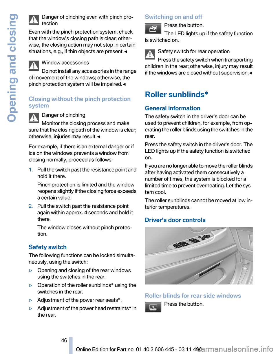
Driver's door controls Roller blinds for rear side windows
Press the button. Seite 46
46 Online Edition for Part no. 01 40 2 606 445 - 03 11 490
Opening and closing
Page 58 of 297
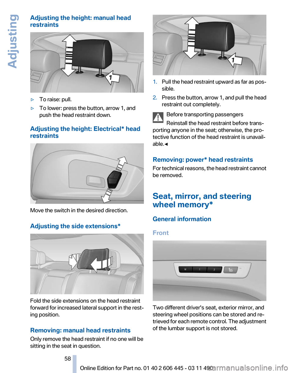
Adjusting the height: manual head
restraints
▷
To raise: pull.
▷ To lower: press the button, arrow 1, and
push the head restraint down.
Adjusting the height: Electrical* head
restraints Move the switch in the desired direction.
Adjusting the side extensions
*Fold the side extensions on the head restraint
forward
for increased lateral support in the rest‐
ing position.
Removing: manual head restraints
Only remove the head restraint if no one will be
sitting in the seat in question. 1.
Pull the head restraint upward as far as pos‐
sible.
2. Press the button, arrow 1, and pull the head
restraint out completely.
Before transporting passengers
Reinstall the head restraint before trans‐
porting anyone in the seat; otherwise, the pro‐
tective function of the head restraint is unavail‐
able.◀
Removing: power* head restraints
For
technical reasons, the head restraint cannot
be removed.
Seat, mirror, and steering
wheel memory*
General information
Front Two different driver's seat, exterior mirror, and
steering wheel positions can be stored and re‐
trieved
for each remote control. The adjustment
of the lumbar support is not stored. Seite 58
58 Online Edition for Part no. 01 40 2 606 445 - 03 11 490
Adjusting
Page 62 of 297
Transporting children safely
The right place for children
Note
Children in the vehicle
Do not leave children unattended in the
vehicle; otherwise, they could endanger them‐
selves and other persons, e.g., by opening the
doors.◀
Children should always be in the rear
Accident research shows that the safest place
for children is in the back seat.
Transporting children in the rear
Only transport children younger than
13
years of age or shorter than 5 ft/150 cm in the
rear in child restraint fixing systems provided in
accordance with the age, weight and size of the
child; otherwise, there is an increased risk of in‐
jury in an accident.
Children 13 years of age or older must wear a
safety belt as soon as a suitable child restraint
fixing system can no longer be used, due to their
age, weight and size.◀
Children on the front passenger seat
Should it ever be necessary to use a child re‐
straint fixing system in the front passenger seat,
make sure that the front, knee and side airbags
on the front passenger side are deactivated. Au‐
tomatic deactivation of front passenger airbags,
refer to page 90.
Deactivating the front passenger airbags
If a child restraint fixing system is used in
the front passenger seat, the front passenger
airbags must be deactivated; otherwise, there is
an increased risk of injury to the child when the
airbags are triggered, even with a child restraint
fixing system.◀ Installing child restraint fixing
systems
Before mounting
If the rear seat backrests are adjustable:
Before mounting child restraint fixing systems,
return all of the rear seat backrests to the basic
position.
Notes
Manufacturer's information for child re‐
straint fixing systems
To select, mount and use child restraint fixing
systems, observe the information provided by
the system manufacturer; otherwise, the pro‐
tective effect can be impaired.
◀
On the front passenger seat
After installing a child restraint fixing system in
the front passenger seat, make sure that the
front, knee and side airbags on the front pas‐
senger side are deactivated.
Deactivate the front passenger airbags auto‐
matically, refer to page 90.
Deactivating the front passenger airbags
If a child restraint fixing system is used in
the front passenger seat, the front passenger
airbags must be deactivated; otherwise, there is
an increased risk of injury to the child when the
airbags are triggered, even with a child restraint
fixing system.◀
Seat position and height
Before installing a child restraint fixing system,
move the front passenger seat as far back as
possible and adjust its height to the middle po‐
sition to obtain the best possible position for the
belt and to offer optimal protection in the event
of an accident.
Do not change the seat position and height after
this. Seite 62
62 Online Edition for Part no. 01 40 2 606 445 - 03 11 490
Transporting children safely
Page 64 of 297
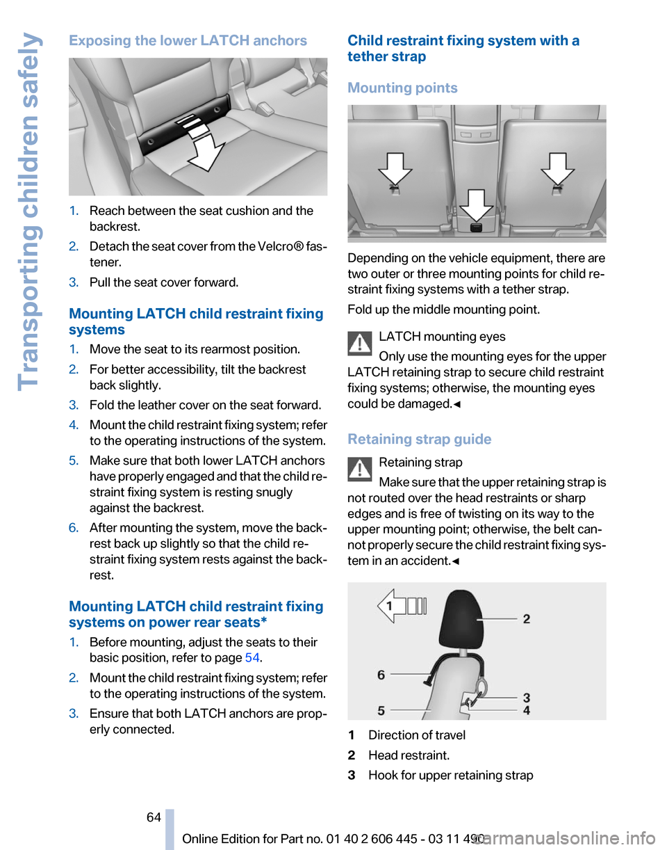
Exposing the lower LATCH anchors
1.
Reach between the seat cushion and the
backrest.
2. Detach the seat cover from the Velcro® fas‐
tener.
3. Pull the seat cover forward.
Mounting LATCH child restraint fixing
systems
1. Move the seat to its rearmost position.
2. For better accessibility, tilt the backrest
back slightly.
3. Fold the leather cover on the seat forward.
4. Mount the child restraint fixing system; refer
to the operating instructions of the system.
5. Make sure that both lower LATCH anchors
have
properly engaged and that the child re‐
straint fixing system is resting snugly
against the backrest.
6. After mounting the system, move the back‐
rest back up slightly so that the child re‐
straint
fixing system rests against the back‐
rest.
Mounting LATCH child restraint fixing
systems on power rear seats
*
1. Before mounting, adjust the seats to their
basic position, refer to page 54.
2. Mount the child restraint fixing system; refer
to the operating instructions of the system.
3. Ensure that both LATCH anchors are prop‐
erly connected. Child restraint fixing system with a
tether strap
Mounting points
Depending on the vehicle equipment, there are
two outer or three mounting points for child re‐
straint fixing systems with a tether strap.
Fold up the middle mounting point.
LATCH mounting eyes
Only
use the mounting eyes for the upper
LATCH retaining strap to secure child restraint
fixing systems; otherwise, the mounting eyes
could be damaged.◀
Retaining strap guide
Retaining strap
Make sure that the upper retaining strap is
not routed over the head restraints or sharp
edges and is free of twisting on its way to the
upper mounting point; otherwise, the belt can‐
not properly secure the child restraint fixing sys‐
tem in an accident.◀ 1
Direction of travel
2 Head restraint.
3 Hook for upper retaining strap Seite 64
64 Online Edition for Part no. 01 40 2 606 445 - 03 11 490
Transporting children safely
Page 65 of 297
4
Mounting point/eye
5 Seat backrest
6 Upper retaining strap
Attaching the upper retaining strap to
the mounting point
1. Raise the head restraint.
2. Guide the upper retaining strap between the
supports of the head restraint.
3. Attach the hooks of the retaining strap to the
mounting eyes.
4. Tighten the retaining strap by pulling it
down.
5. Lower the head restraint.
Locking the doors and
windows
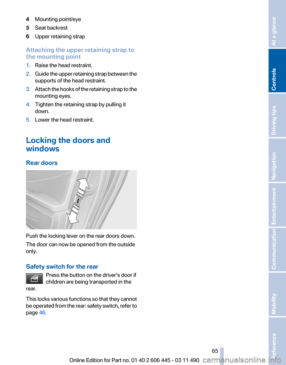
Rear doors Push the locking lever on the rear doors down.
The door can now be opened from the outside
only.
Safety switch for the rear
Press the button on the driver's door if
children are being transported in the
rear.
This
locks various functions so that they cannot
be operated from the rear: safety switch, refer to
page 46. Seite 65
65Online Edition for Part no. 01 40 2 606 445 - 03 11 490
Reference Mobility Communication Entertainment Navigation Driving tips
Controls At a glance
Page 75 of 297
Sport program and manual mode M/S
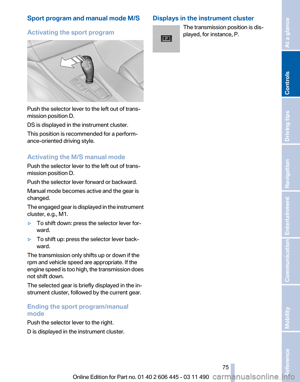
Activating the sport program
Push the selector lever to the left out of trans‐
mission position D.
DS is displayed in the instrument cluster.
This position is recommended for a perform‐
ance-oriented driving style.
Activating the M/S manual mode
Push the selector lever to the left out of trans‐
mission position D.
Push the selector lever forward or backward.
Manual mode becomes active and the gear is
changed.
The
engaged gear is displayed in the instrument
cluster, e.g., M1.
▷ To shift down: press the selector lever for‐
ward.
▷ To shift up: press the selector lever back‐
ward.
The transmission only shifts up or down if the
rpm and vehicle speed are appropriate. If the
engine
speed is too high, the transmission does
not shift down.
The selected gear is briefly displayed in the in‐
strument cluster, followed by the current gear.
Ending the sport program/manual
mode
Push the selector lever to the right.
D is displayed in the instrument cluster. Displays in the instrument cluster
The transmission position is dis‐
played, for instance, P. Seite 75
75Online Edition for Part no. 01 40 2 606 445 - 03 11 490
Reference Mobility Communication Entertainment Navigation Driving tips
Controls At a glance