rear entertainment BMW 535I XDRIVE 2011 F10 User Guide
[x] Cancel search | Manufacturer: BMW, Model Year: 2011, Model line: 535I XDRIVE, Model: BMW 535I XDRIVE 2011 F10Pages: 304, PDF Size: 10.18 MB
Page 83 of 304
ually switch off the high beams in situations
where this is required to avoid a safety risk.
◀
The system is not fully functional in situations
such as the following, and driver intervention
may be necessary:
▷ In very unfavorable weather conditions,
such as fog or heavy precipitation.
▷ In detecting poorly-lit road users, such as
pedestrians, cyclists, horseback riders and
wagons; when driving close to train or ship
traffic; and at animal crossings.
▷ In tight curves, on hilltops or in depressions,
in cross traffic or half-obscured oncoming
traffic on freeways.
▷ In poorly-lit towns and cities and in the pres‐
ence of highly reflective signs.
▷ At low speeds.
▷ When the windshield in front of the interior
rearview mirror is fogged over, dirty or cov‐
ered with stickers, etc.
Camera The camera is located on the front of the interior
rearview mirror.
Keep the area in front of the interior rearview
mirror clear.
Fog lamps
Front fog lamps*
The parking lamps or low beams must be
switched on.
Press the button. The green indicator
lamp lights up. If the automatic headlamp control, refer to
page
81, is activated, the low beams will come
on automatically when you switch on the front
fog lamps.
Instrument lighting
Adjusting
The parking lamps or low beams
must
be switched on to adjust the
brightness.
Adjust the brightness using the
thumbwheel.
Interior lamps
General information
The interior lamps, footwell lamps, entry lamps
and courtesy lamps are controlled automati‐
cally.
The brightness of some of these lamps is influ‐
enced by the thumbwheel for the instrument
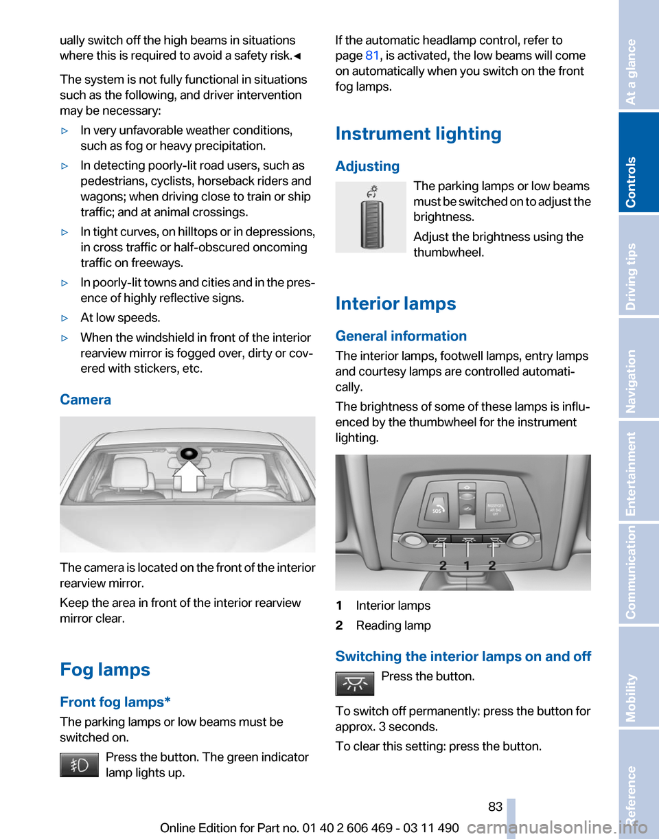
lighting. 1
Interior lamps
2 Reading lamp
Switching the interior lamps on and off Press the button.
To switch off permanently: press the button for
approx. 3 seconds.
To clear this setting: press the button. Seite 83
83Online Edition for Part no. 01 40 2 606 469 - 03 11 490
Reference Mobility Communication Entertainment Navigation Driving tips
Controls At a glance
Page 85 of 304
Safety
Airbags
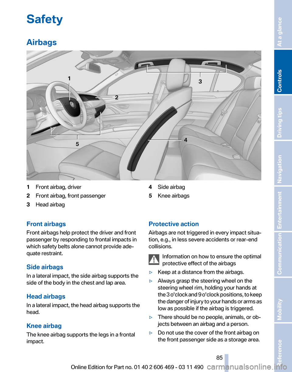
1
Front airbag, driver
2 Front airbag, front passenger
3 Head airbag 4
Side airbag
5 Knee airbags
Front airbags
Front airbags help protect the driver and front
passenger by responding to frontal impacts in
which safety belts alone cannot provide ade‐
quate restraint.
Side airbags
In a lateral impact, the side airbag supports the
side of the body in the chest and lap area.
Head airbags
In
a lateral impact, the head airbag supports the
head.
Knee airbag
The knee airbag supports the legs in a frontal
impact. Protective action
Airbags are not triggered in every impact situa‐
tion, e.g., in less severe accidents or rear-end
collisions.
Information on how to ensure the optimal
protective effect of the airbags
▷ Keep at a distance from the airbags.
▷ Always grasp the steering wheel on the
steering wheel rim, holding your hands at
the
3 o'clock and 9 o'clock positions, to keep
the danger of injury to your hands or arms as
low as possible if the airbag is triggered.
▷ There should be no people, animals, or ob‐
jects between an airbag and a person.
▷ Do not use the cover of the front airbag on
the front passenger side as a storage area. Seite 85
85Online Edition for Part no. 01 40 2 606 469 - 03 11 490
Reference Mobility Communication Entertainment Navigation Driving tips
Controls At a glance
Page 87 of 304
Child restraint fixing system in the front
passenger seat
Before
transporting a child on the front passen‐
ger seat, see the safety notes and instructions
under Children on the front passenger seat.◀
Malfunction of the automatic
deactivation system
When transporting older children and adults, the
front passenger airbags may be deactivated in
certain sitting positions. In this case, the indica‐
tor lamp for the front passenger airbags lights
up.
In this case, change the sitting position so that
the front passenger airbags are activated and
the indicator lamp goes out.
If it is not possible to activate the airbags, have
the person sit in the rear.
To make sure that the occupied seat cushion
can be evaluated correctly
▷ Do not attach covers, cushions, ball mats or
other items to the front passenger seat un‐
less they are specifically recommended by
the manufacturer of your vehicle.
▷ Do not place any objects on the front pas‐
senger seat.
▷ Do not place objects under the seat that
could press against the seat from below.
Indicator lamp for the front passenger
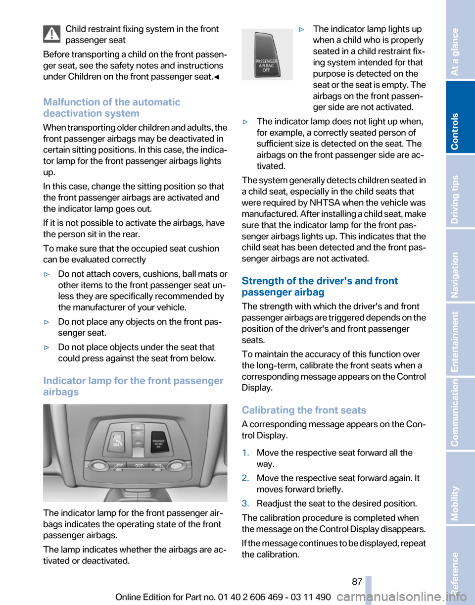
airbags The indicator lamp for the front passenger air‐
bags indicates the operating state of the front
passenger airbags.
The lamp indicates whether the airbags are ac‐
tivated or deactivated. ▷
The indicator lamp lights up
when a child who is properly
seated in a child restraint fix‐
ing system intended for that
purpose is detected on the
seat
or the seat is empty. The
airbags on the front passen‐
ger side are not activated.
▷ The indicator lamp does not light up when,
for example, a correctly seated person of
sufficient size is detected on the seat. The
airbags on the front passenger side are ac‐
tivated.
The system generally detects children seated in
a child seat, especially in the child seats that
were required by NHTSA when the vehicle was
manufactured.
After installing a child seat, make
sure that the indicator lamp for the front pas‐
senger airbags lights up. This indicates that the
child seat has been detected and the front pas‐
senger airbags are not activated.
Strength of the driver's and front
passenger airbag
The strength with which the driver's and front
passenger airbags are triggered depends on the
position of the driver's and front passenger
seats.
To maintain the accuracy of this function over
the long-term, calibrate the front seats when a
corresponding message appears on the Control
Display.
Calibrating the front seats
A corresponding message appears on the Con‐
trol Display.
1. Move the respective seat forward all the
way.
2. Move the respective seat forward again. It
moves forward briefly.
3. Readjust the seat to the desired position.
The calibration procedure is completed when
the
message on the Control Display disappears.
If the message continues to be displayed, repeat
the calibration. Seite 87
87Online Edition for Part no. 01 40 2 606 469 - 03 11 490
Reference Mobility Communication Entertainment Navigation Driving tips
Controls At a glance
Page 93 of 304
Switching on/off
Press the button.
▷ On: the LED lights up.
▷ Off: the LED goes out.
The system can issue warnings at speeds above
approx. 30 mph/50 km/h.
The state is stored for the remote control cur‐
rently in use.
Display Information stage
The dimmed lamp in the mirror housing indi‐
cates when there are vehicles in the blind spot
or approaching from behind.
Warning
If the turn signal is set while a vehicle is in the
critical zone, the steering wheel vibrates briefly
and the lamp in the mirror housing flashes
brightly.
The warning stops when the turn signal is
switched
off, or the other vehicle leaves the crit‐
ical zone. System limits
Personal responsibility
The system cannot serve as a substitute
for the driver's personal judgment of the traffic
situation.
In
the event of a warning, do not jerk the steering
wheel, as you may lose control over the vehi‐
cle.◀
The system may not be fully functional in the
following situations:
▷ When a vehicle is approaching at a speed
much faster than your own.
▷ In heavy fog, rain or snowfall.
▷ In tight curves or on narrow lanes.
Malfunctions
Steering wheel vibration
Frequent
activation of the steering wheel vibra‐
tion causes the system to overheat.
This causes Active Blind Spot Detection to be‐
come deactivated.
Let the system cool and reactivate it by pressing
the button.
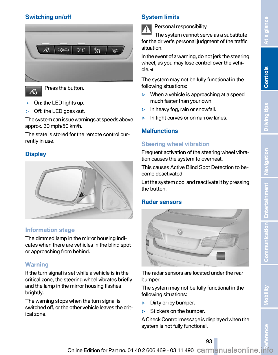
Radar sensors The radar sensors are located under the rear
bumper.
The system may not be fully functional in the
following situations:
▷
Dirty or icy bumper.
▷ Stickers on the bumper.
A Check Control message is displayed when the
system is not fully functional. Seite 93
93Online Edition for Part no. 01 40 2 606 469 - 03 11 490
Reference Mobility Communication Entertainment Navigation Driving tips
Controls At a glance
Page 95 of 304
Driving stability control systems
Antilock Brake System ABS
ABS
prevents locking of the wheels during brak‐
ing.
The vehicle remains steerable even during full
brake applications, thus increasing active
safety.
ABS is operational every time you start the en‐
gine.
Brake assistant
When you apply the brakes rapidly, this system
automatically produces the maximum braking
force boost. It thus helps to achieve the shortest
possible braking distance during full braking.
This system utilizes all of the benefits provided
by ABS.
Do not reduce the pressure on the brake pedal
for the duration of the full braking.
Adaptive brake assistant
In combination with the Active Cruise Control,
this system ensures that the brakes respond
even more rapidly when braking in critical situa‐
tions. Refer also to Collision warning, refer to
page 108.
Drive-off assistant
This system supports driving away on gradients.
The parking brake is not required.
1. Hold the vehicle in place with the foot brake.
2. Release the foot brake and drive away with‐
out delay.
After the foot brake is released, the vehicle is
held in place for approx. 2 seconds.
Depending on the vehicle load, the vehicle may
roll back slightly. Driving off without delay
After
releasing the foot brake, start driving
without delay, since the drive-off assistant will
not hold the vehicle in place for more than ap‐
prox. 2 seconds and the vehicle will begin rolling
back.◀
DSC Dynamic Stability
Control
The concept
DSC prevents traction loss in the driving wheels
when driving away and accelerating.
DSC also recognizes unstable vehicle condi‐
tions, such as fishtailing or nose-diving. Subject
to physical limits, DSC helps to keep the vehicle
on a steady course by reducing engine speed
and by applying brakes at individual wheels.
Adjust your driving style to the situation
An appropriate driving style is always the
responsibility of the driver.
The laws of physics cannot be repealed, even
with DSC.
Therefore, do not reduce the additional safety
margin by driving in a risky manner.◀
Indicator/warning lamps
The indicator lamp flashes: DSC con‐
trols the drive forces and brake forces.
The indicator lamp lights up: DSC has
failed.
Deactivating DSC: DSC OFF
When DSC is deactivated, driving stability is re‐
duced during acceleration and when driving in
bends.
Stabilizing interventions by the Integral Active
Steering* system are only performed by the rear
axle steering. Seite 95
95Online Edition for Part no. 01 40 2 606 469 - 03 11 490
Reference Mobility Communication Entertainment Navigation Driving tips
Controls At a glance
Page 99 of 304
2.
Have the system checked if the warning
lamp
does not go out after moving the steer‐
ing wheel approx. 6 times or if the steering
wheel is at an angle.
Using snow chains
Ensure
that the rear axle steering is deactivated
when using snow chains, refer to page 253.
Programs
The system offers two different programs.
The programs can be selected via Dynamic Driv‐
ing Control, refer to page 99.
SPORT
Consistently sporty tuning of the Integral Active
Steering for greater driving agility.
NORMAL
Balanced tuning of the Integral Active Steering
for optimal traveling comfort.
Malfunction
In the event of a malfunction, the steering wheel
must be turned further, while the vehicle re‐
sponds more sensitively to steering wheel
movements in the higher speed range.
The stability-enhancing intervention may be de‐
activated.
Proceed cautiously and drive defensively.
Have the system checked.
Dynamic Driving Control*
The concept
Dynamic Driving Control can be used to adjust
the driving dynamics of the vehicle. Several pro‐
grams are available for this purpose; they can be
activated using the two Dynamic Driving Control
buttons. Operating the programs Press the button Program
DSC OFF
TRACTION
SPORT+
SPORT
NORMAL
COMFORT*
For Dynamic Damper Control*, the lower button
is labeled with COMFORT.
Automatic program change
The
system automatically switches to NORMAL
in the following situations:
▷ Failure of Integral Active Steering*.
▷ Failure of Dynamic Damping Control*.
▷ The vehicle has a flat tire.
DSC OFF
When
DSC OFF, refer to page 95, is active, driv‐
ing stability is limited during acceleration and
when driving in bends.
TRACTION
When TRACTION is active, the vehicle has max‐
imum traction on loose road surfaces. DTC Dy‐
namic Traction Control, refer to page 96, is ac‐
tivated. Driving stability is limited during
acceleration and when driving in bends.
SPORT+
Sporty driving with optimized chassis and sus‐
pension during limited driving stabilization.
Dynamic Traction Control is switched on.
The driver handles several of the stabilization
tasks.
Activating SPORT+
Press the button repeatedly until
SPORT+ appears in the tachometer Seite 99
99Online Edition for Part no. 01 40 2 606 469 - 03 11 490
Reference Mobility Communication Entertainment Navigation Driving tips
Controls At a glance
Page 111 of 304
Resuming the desired speed
Press the button.
The stored speed is reached and maintained.
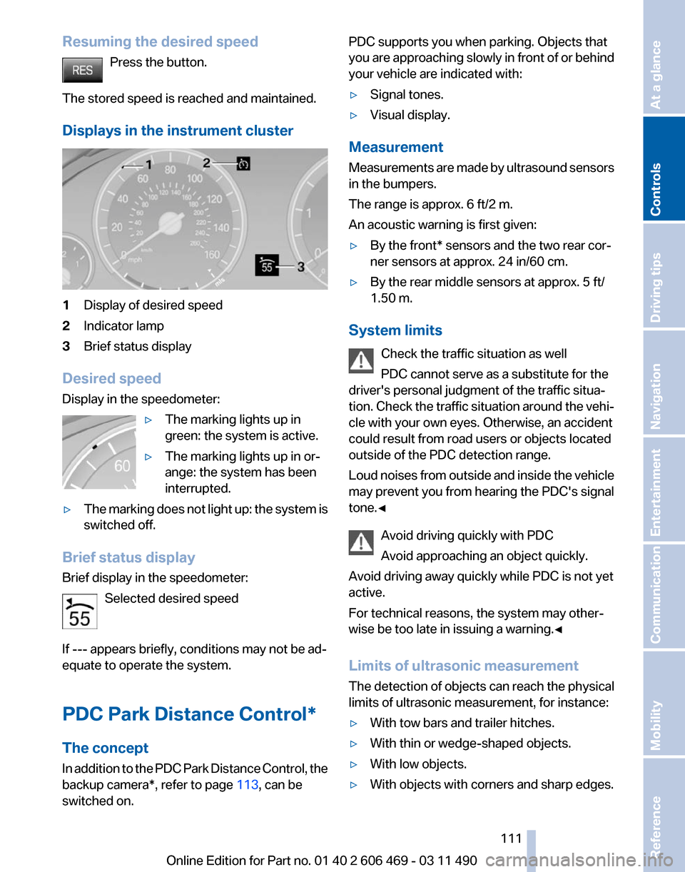
Displays in the instrument cluster 1
Display of desired speed
2 Indicator lamp
3 Brief status display
Desired speed
Display in the speedometer: ▷The marking lights up in
green: the system is active.
▷ The marking lights up in or‐
ange: the system has been
interrupted.
▷ The marking does not light up: the system is
switched off.
Brief status display
Brief display in the speedometer: Selected desired speed
If --- appears briefly, conditions may not be ad‐
equate to operate the system.
PDC Park Distance Control*
The concept
In
addition to the PDC Park Distance Control, the
backup camera*, refer to page 113, can be
switched on. PDC supports you when parking. Objects that
you
are approaching slowly in front of or behind
your vehicle are indicated with:
▷ Signal tones.
▷ Visual display.
Measurement
Measurements
are made by ultrasound sensors
in the bumpers.
The range is approx. 6 ft/2 m.
An acoustic warning is first given:
▷ By the front* sensors and the two rear cor‐
ner sensors at approx. 24 in/60 cm.
▷ By the rear middle sensors at approx. 5 ft/
1.50 m.
System limits Check the traffic situation as well
PDC cannot serve as a substitute for the
driver's personal judgment of the traffic situa‐
tion.
Check the traffic situation around the vehi‐
cle with your own eyes. Otherwise, an accident
could result from road users or objects located
outside of the PDC detection range.
Loud noises from outside and inside the vehicle
may prevent you from hearing the PDC's signal
tone.◀
Avoid driving quickly with PDC
Avoid approaching an object quickly.
Avoid driving away quickly while PDC is not yet
active.
For technical reasons, the system may other‐
wise be too late in issuing a warning.◀
Limits of ultrasonic measurement
The detection of objects can reach the physical
limits of ultrasonic measurement, for instance:
▷ With tow bars and trailer hitches.
▷ With thin or wedge-shaped objects.
▷ With low objects.
▷ With objects with corners and sharp edges. Seite 111
111Online Edition for Part no. 01 40 2 606 469 - 03 11 490
Reference Mobility Communication Entertainment Navigation Driving tips
Controls At a glance
Page 113 of 304
If the backup camera image was selected last, it
again
appears on the display. To switch to PDC:
1. "Rear view camera" Select the symbol
on the Control Display.
2. Press the controller.
The setting is stored for the remote control cur‐
rently in use.
Zoom view*
On
the left part of the display screen, the vehicle
is shown enlarged. ▷
Forward gear or transmission position D en‐
gaged: front area of the vehicle.
▷ Reverse gear or transmission position R en‐
gaged: rear area of the vehicle.
Display on the Control Display
Switching
on the backup camera via the
iDrive
With PDC activated: "Rear view camera"
The
backup camera image is displayed. The set‐
ting is stored for the remote control currently in
use.
Malfunction
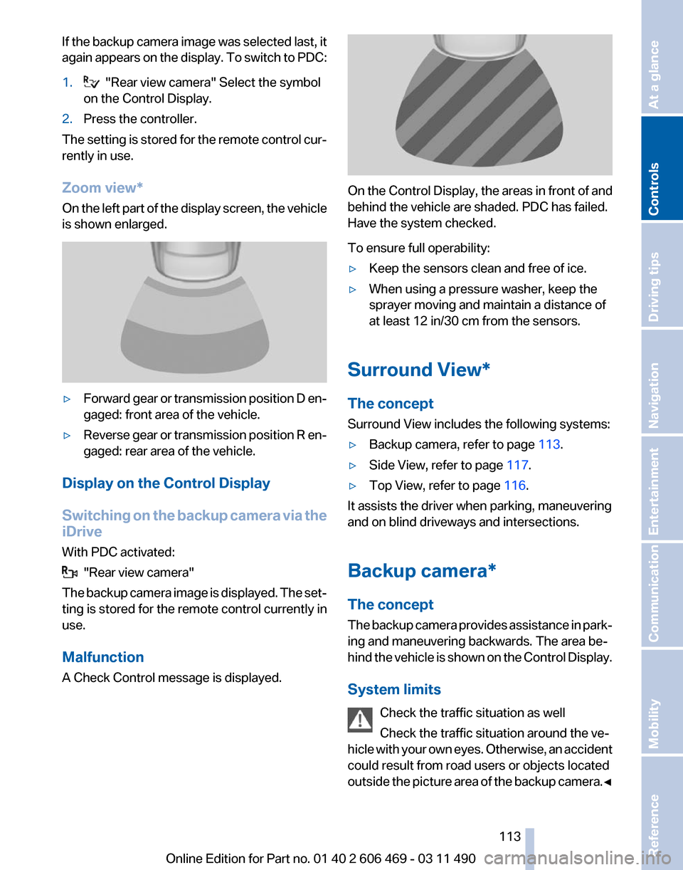
A Check Control message is displayed. On the Control Display, the areas in front of and
behind the vehicle are shaded. PDC has failed.
Have the system checked.
To ensure full operability:
▷
Keep the sensors clean and free of ice.
▷ When using a pressure washer, keep the
sprayer moving and maintain a distance of
at least 12 in/30 cm from the sensors.
Surround View*
The concept
Surround View includes the following systems:
▷ Backup camera, refer to page 113.
▷ Side View, refer to page 117.
▷ Top View, refer to page 116.
It assists the driver when parking, maneuvering
and on blind driveways and intersections.
Backup camera*
The concept
The
backup camera provides assistance in park‐
ing and maneuvering backwards. The area be‐
hind the vehicle is shown on the Control Display.
System limits
Check the traffic situation as well
Check the traffic situation around the ve‐
hicle with your own eyes. Otherwise, an accident
could result from road users or objects located
outside the picture area of the backup camera.◀ Seite 113
113Online Edition for Part no. 01 40 2 606 469 - 03 11 490
Reference Mobility Communication Entertainment Navigation Driving tips
Controls At a glance
Page 115 of 304
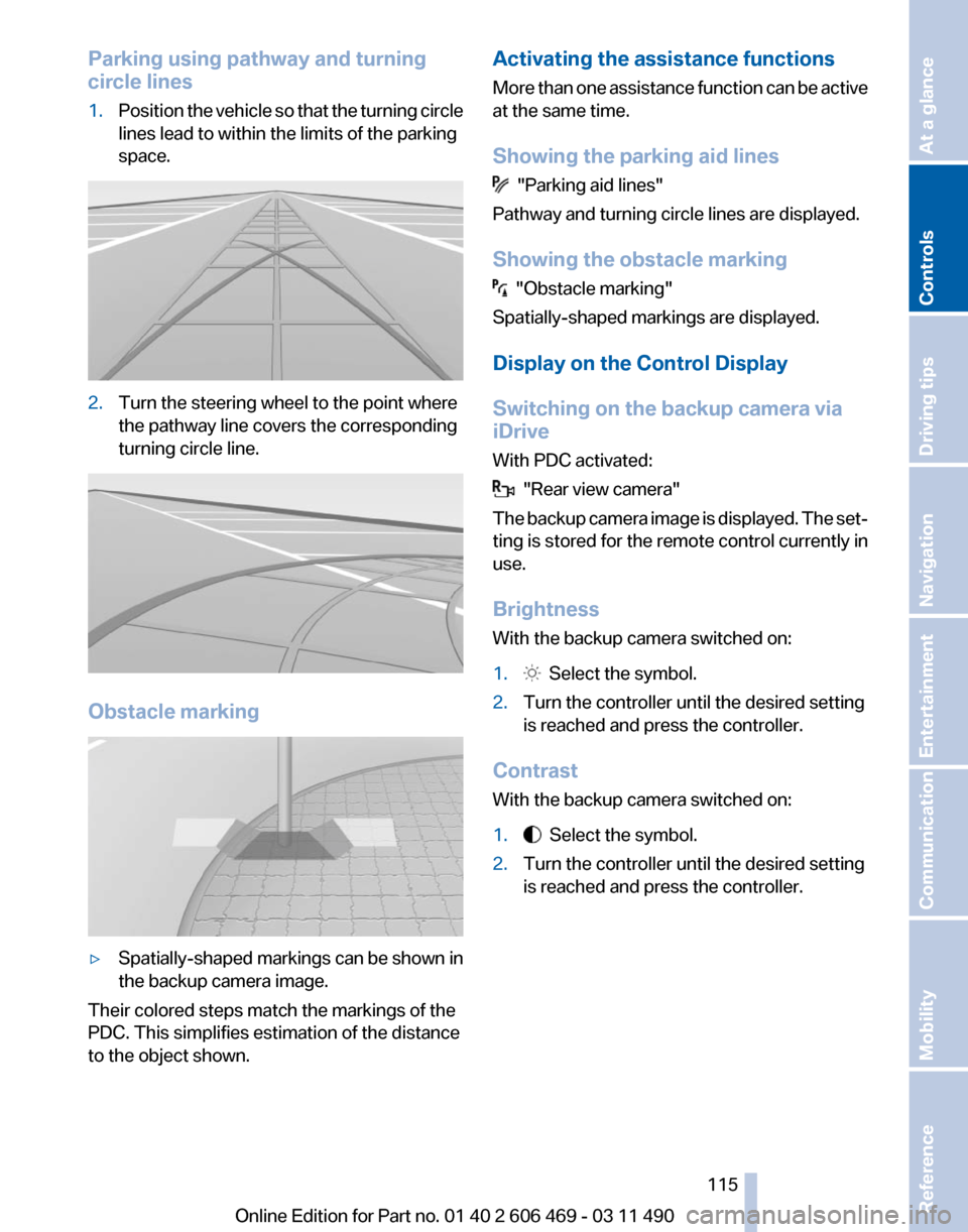
Parking using pathway and turning
circle lines
1.
Position the vehicle so that the turning circle
lines lead to within the limits of the parking
space. 2.
Turn the steering wheel to the point where
the pathway line covers the corresponding
turning circle line. Obstacle marking
▷
Spatially-shaped markings can be shown in
the backup camera image.
Their colored steps match the markings of the
PDC. This simplifies estimation of the distance
to the object shown. Activating the assistance functions
More
than one assistance function can be active
at the same time.
Showing the parking aid lines "Parking aid lines"
Pathway and turning circle lines are displayed.
Showing the obstacle marking "Obstacle marking"
Spatially-shaped markings are displayed.
Display on the Control Display
Switching on the backup camera via
iDrive
With PDC activated: "Rear view camera"
The
backup camera image is displayed. The set‐
ting is stored for the remote control currently in
use.
Brightness
With the backup camera switched on:
1. Select the symbol.
2. Turn the controller until the desired setting
is reached and press the controller.
Contrast
With the backup camera switched on:
1. Select the symbol.
2. Turn the controller until the desired setting
is reached and press the controller.
Seite 115
115Online Edition for Part no. 01 40 2 606 469 - 03 11 490
Reference Mobility Communication Entertainment Navigation Driving tips
Controls At a glance
Page 117 of 304
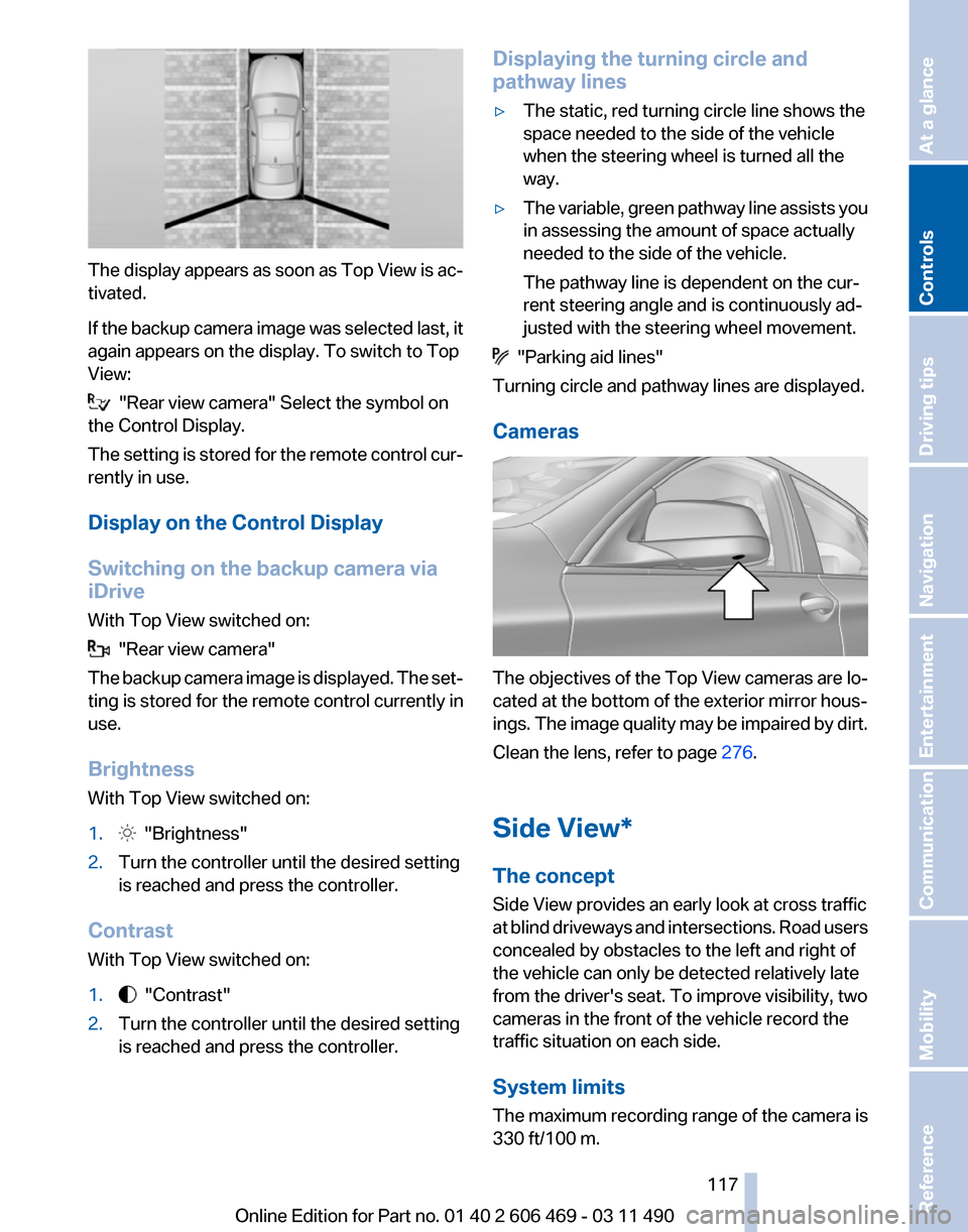
The display appears as soon as Top View is ac‐
tivated.
If
the backup camera image was selected last, it
again appears on the display. To switch to Top
View: "Rear view camera" Select the symbol on
the Control Display.
The
setting is stored for the remote control cur‐
rently in use.
Display on the Control Display
Switching on the backup camera via
iDrive
With Top View switched on: "Rear view camera"
The
backup camera image is displayed. The set‐
ting is stored for the remote control currently in
use.
Brightness
With Top View switched on:
1. "Brightness"
2. Turn the controller until the desired setting
is reached and press the controller.
Contrast
With Top View switched on:
1. "Contrast"
2. Turn the controller until the desired setting
is reached and press the controller. Displaying the turning circle and
pathway lines
▷
The static, red turning circle line shows the
space needed to the side of the vehicle
when the steering wheel is turned all the
way.
▷ The variable, green pathway line assists you
in assessing the amount of space actually
needed to the side of the vehicle.
The pathway line is dependent on the cur‐
rent steering angle and is continuously ad‐
justed with the steering wheel movement. "Parking aid lines"
Turning circle and pathway lines are displayed.
Cameras The objectives of the Top View cameras are lo‐
cated at the bottom of the exterior mirror hous‐
ings.
The image quality may be impaired by dirt.
Clean the lens, refer to page 276.
Side View*
The concept
Side View provides an early look at cross traffic
at blind driveways and intersections. Road users
concealed by obstacles to the left and right of
the vehicle can only be detected relatively late
from the driver's seat. To improve visibility, two
cameras in the front of the vehicle record the
traffic situation on each side.
System limits
The maximum recording range of the camera is
330 ft/100 m.
Seite 117
117Online Edition for Part no. 01 40 2 606 469 - 03 11 490
Reference Mobility Communication Entertainment Navigation Driving tips
Controls At a glance