steering wheel BMW 535I XDRIVE 2013 Owner's Guide
[x] Cancel search | Manufacturer: BMW, Model Year: 2013, Model line: 535I XDRIVE, Model: BMW 535I XDRIVE 2013Pages: 246, PDF Size: 5.39 MB
Page 138 of 246
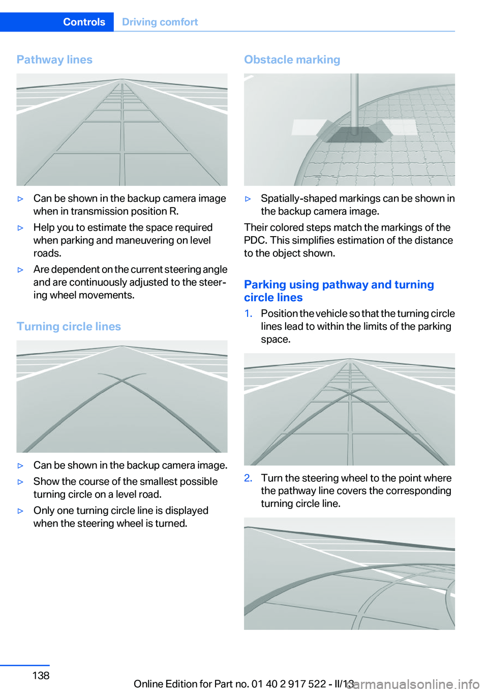
Pathway lines▷Can be shown in the backup camera image
when in transmission position R.▷Help you to estimate the space required
when parking and maneuvering on level
roads.▷Are dependent on the current steering angle
and are continuously adjusted to the steer‐
ing wheel movements.
Turning circle lines
▷Can be shown in the backup camera image.▷Show the course of the smallest possible
turning circle on a level road.▷Only one turning circle line is displayed
when the steering wheel is turned.Obstacle marking▷Spatially-shaped markings can be shown in
the backup camera image.
Their colored steps match the markings of the
PDC. This simplifies estimation of the distance
to the object shown.
Parking using pathway and turning
circle lines
1.Position the vehicle so that the turning circle
lines lead to within the limits of the parking
space.2.Turn the steering wheel to the point where
the pathway line covers the corresponding
turning circle line.Seite 138ControlsDriving comfort138
Online Edition for Part no. 01 40 2 917 522 - II/13
Page 140 of 246
The Top View and PDC images are displayed if
the system is switched on via iDrive.
Automatic deactivation during forward
travel
The system switches off when a certain driving
distance or speed is exceeded.
Switch the system back on if necessary.
Switching on/off manually Press the button.▷On: the LED lights up.▷Off: the LED goes out.
Top View is displayed, switch on the backup
camera via the iDrive, refer to page 140.
Switching on the backup camera via the
iDrive
With Top View switched on:
"Rear view camera"
The backup camera image is displayed. The set‐
ting is stored for the remote control currently in
use.
Display
Visual warning
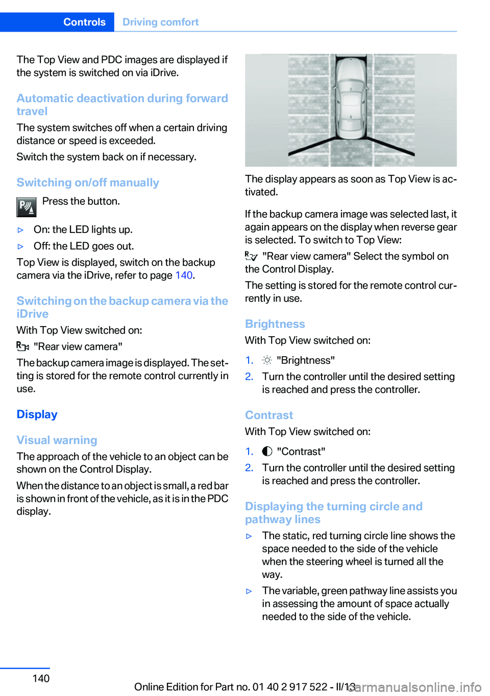
The approach of the vehicle to an object can be
shown on the Control Display.
When the distance to an object is small, a red bar
is shown in front of the vehicle, as it is in the PDC
display.
The display appears as soon as Top View is ac‐
tivated.
If the backup camera image was selected last, it
again appears on the display when reverse gear
is selected. To switch to Top View:
"Rear view camera" Select the symbol on
the Control Display.
The setting is stored for the remote control cur‐
rently in use.
Brightness
With Top View switched on:
1. "Brightness"2.Turn the controller until the desired setting
is reached and press the controller.
Contrast
With Top View switched on:
1. "Contrast"2.Turn the controller until the desired setting
is reached and press the controller.
Displaying the turning circle and
pathway lines
▷The static, red turning circle line shows the
space needed to the side of the vehicle
when the steering wheel is turned all the
way.▷The variable, green pathway line assists you
in assessing the amount of space actually
needed to the side of the vehicle.Seite 140ControlsDriving comfort140
Online Edition for Part no. 01 40 2 917 522 - II/13
Page 141 of 246
The pathway line is dependent on the cur‐
rent steering angle and is continuously ad‐
justed with the steering wheel movement.
"Parking aid lines"
Turning circle and pathway lines are displayed.
System limits
Top View cannot be used in the following situa‐
tions:
▷With a door open.▷With the trunk lid open.▷With an exterior mirror folded in.▷In poor light.
A Check Control message is displayed in some
of these situations.
Side View
The concept
Side View provides an early look at cross traffic
at blind driveways and intersections. Road users
concealed by obstacles to the left and right of
the vehicle can only be detected relatively late
from the driver's seat. To improve visibility, two
cameras in the front of the vehicle record the
traffic situation on each side.
Notes
The images from both cameras are shown si‐
multaneously on the Control Display.
Check the traffic situation as well
Check the traffic situation around the ve‐
hicle on blind driveways and intersections with
your own eyes. Otherwise, an accident could re‐
sult from road users or objects located outside
the picture area of the Side View cameras.◀
At a glance
Button in the vehicle
Side View
Cameras
Two cameras integrated in the bumpers capture
the image.
The two camera lenses are located on the sides
of the bumper.
The image quality may be impaired by dirt.
Clean the lens, refer to page 229.
Switching on/off
Switching on/off manually Press the button.
Automatic deactivation during forward
travel
The system switches off when a certain driving
distance or speed is exceeded.
Seite 141Driving comfortControls141
Online Edition for Part no. 01 40 2 917 522 - II/13
Page 145 of 246
▷The parking procedure is ac‐
tive. Steering control has
been seized.▷Parking space search is always active when‐
ever the vehicle is moving forwards slow and
straight, even if the system is deactivated.
When the system is deactivated, the dis‐
plays on the Control Display are shown in
gray.
Parking using the parking assistant
Check the traffic situation as well
Loud sounds outside and within the vehi‐
cle can drown out the signal tones of the parking
assistant and PDC.
Check the traffic situation around the vehicle
with your own eyes; otherwise, there is the dan‐
ger of an accident.◀
1.Switch on the parking assistant and activate
it if necessary.
The status of the parking space search is in‐
dicated on the Control Display.2.Follow the instructions on the Control Dis‐
play.
To achieve the best possible parking posi‐
tion, wait for the automatic steering wheel
movement after the gear change when the
vehicle is stationary.
The end of the parking procedure is indi‐
cated on the Control Display.3.Adjust the parking position yourself if nec‐
essary.
Interrupting manually
The parking assistant can be interrupted at any
time:
▷ " Parking Assistant" Select the symbol on
the Control Display.▷Press the button.Interrupting automatically
The system is interrupted automatically in the
following situations:▷If the driver grasps the steering wheel or if
he takes over steering.▷If a gear is selected that does not match the
instruction on the Control Display.▷If a turn signal is activated in the opposite
direction to the desired side for parking.▷If the vehicle speed exceeds approx.
6 mph/10 km/h.▷On snow-covered or slippery road surfaces
if necessary.▷If doors are open.▷If a maximum number of parking attempts or
the time taken for parking is exceeded.
A Check Control message is displayed.
Resume
An interrupted parking procedure can be con‐
tinued if necessary.
Follow the instructions on the Control Display to
do this.
System limits
No parking assistance
The parking assistant does not offer assistance
in the following situations:
▷In tight curves.
Functional limitations
The system may not be fully functional in the
following situations:
▷When sensors are dirty or iced over.▷In heavy fog, rain or snowfall.▷On bumpy road surfaces such as gravel
roads.▷When leaves or snow has collected in the
parking space.Seite 145Driving comfortControls145
Online Edition for Part no. 01 40 2 917 522 - II/13
Page 203 of 246
▷225/55 R 17.▷245/45 R 18.▷245/40 R 19.
Follow the chain manufacturer's instructions.
Make sure that the snow chains are always suf‐
ficiently tight. Retighten as needed according to
the chain manufacturer's instructions.
Do not initialize the Flat Tire Monitor after
mounting snow chains, as doing so may result
in incorrect readings.
Do not initialize the Tire Pressure Monitor after
mounting snow chains, as doing so may result
in incorrect readings.
When driving with snow chains, briefly activate
Dynamic Traction Control if necessary.
Maximum speed with snow chains
Do not exceed a speed of 30 mph/50 km/h when
using snow chains.
Snow chain detection
The concept
When using snow chains, you should set
whether you are driving with or without snow
chains via the iDrive.
The snow chain detection system supports you
by automatically showing the detected state on
the Control Display.
When snow chains are in use, the rear axle steer‐
ing of the Integral Active Steering is deactivated
automatically.
At speeds above the maximum permitted speed
with snow chains of 30 mph/50 km/h, the rear
axle steering is activated again automatically.
Activating the status
1."Settings"2."Tire chains"3."Tire chains installed"Automatic detection
If functioning properly:▷Snow chains are mounted. The setting is not
activated
.
After you drive a short distance, a Check
Control message is shown and the state is
activated automatically.
Confirm the automatic activation.
▷Snow chains are not mounted. The setting
is activated
.
At speeds above 30 mph/50 km/h, a Check
Control message is displayed. Deactivate
the status manually.
If not functioning properly:
▷Snow chains are mounted. The setting is not
activated
.
A Check Control message is not displayed.
The automatic detection system is malfunc‐
tioning. Activate the status manually.
Activating/deactivating rear axle
steering
If the status indicating that snow chains are in
use is activated, the rear axle steering is deacti‐
vated automatically.
At speeds above 30 mph/50 km/h, the rear axle
steering is activated again, even though snow
chains are in use.
Seite 203Wheels and tiresMobility203
Online Edition for Part no. 01 40 2 917 522 - II/13
Page 219 of 246
Starting aid terminals
In the vehicle, only charge the battery via the
starting aid terminals, refer to page 222, in the
engine compartment with the engine off.
Power failure
After a temporary power loss, some equipment
needs to be reinitialized.
Individual settings need to be reprogrammed:▷Seat, mirror, and steering wheel memory:
store the positions again.▷Time: update.▷Date: update.▷Radio station: save again.▷Navigation system: wait for the operability of
the navigation.
Disposing of old batteries
Have old batteries disposed of by your
service center or bring them to a recy‐
cling center.
Maintain the battery in an upright position for
transport and storage. Secure the battery so
that it does not tip over during transport.
Fuses
Notes Replacing fuses
Never attempt to repair a blown fuse and
do not replace a defective fuse with a substitute
of another color or amperage rating; this could
lead to a circuit overload, ultimately resulting in
a fire in the vehicle.◀
Plastic tweezers and information on the fuse
types and locations are stored in the fuse box in
the cargo area.
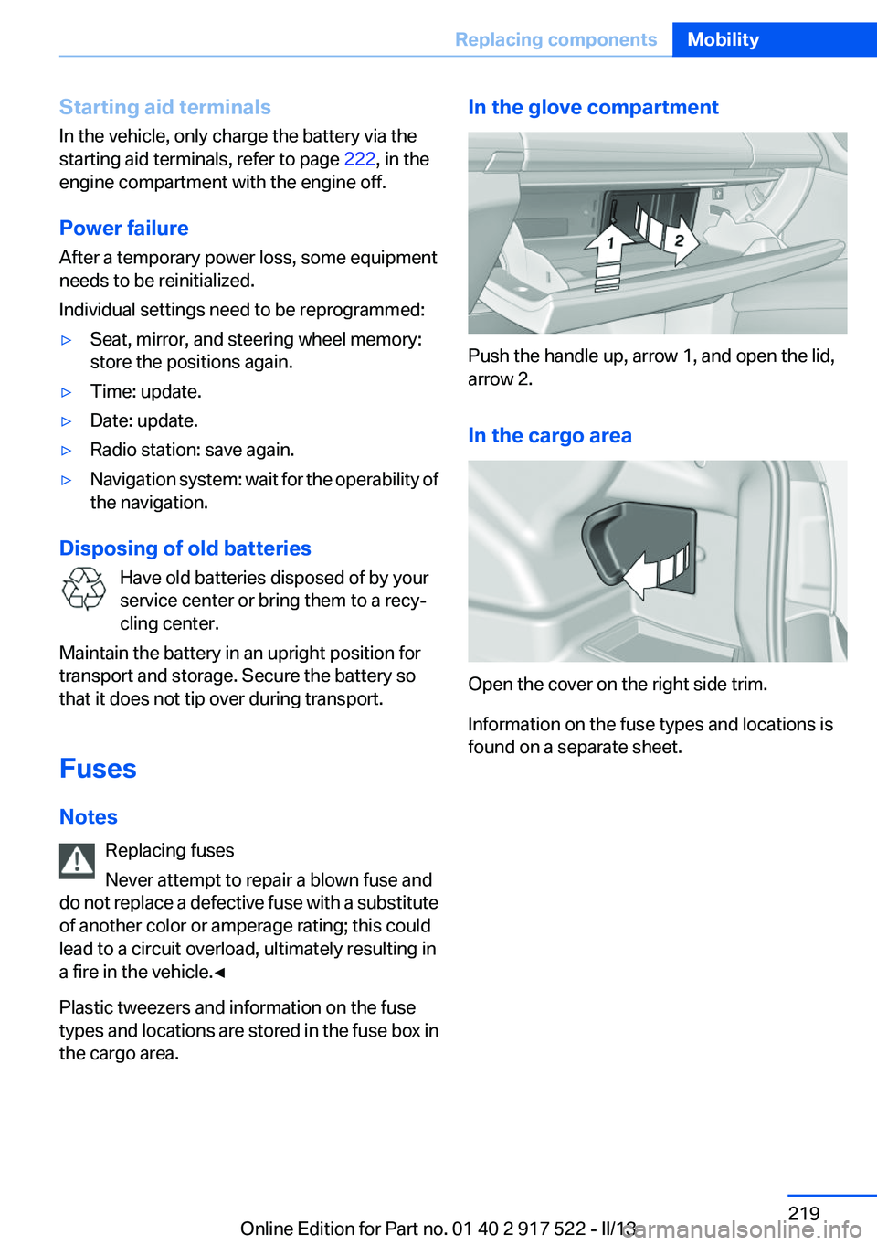
In the glove compartment
Push the handle up, arrow 1, and open the lid,
arrow 2.
In the cargo area
Open the cover on the right side trim.
Information on the fuse types and locations is
found on a separate sheet.
Seite 219Replacing componentsMobility219
Online Edition for Part no. 01 40 2 917 522 - II/13
Page 223 of 246
3.Let both engines run for several minutes.4.Disconnect the jumper cables in the reverse
order.
Check the battery and recharge if necessary.
Tow-starting and towing
Automatic transmission: transporting
your vehicle
Note
Your vehicle is not permitted to be towed.
Therefore, contact a service center in the event
of a breakdown.
Do not have the vehicle towed
Have your vehicle transported on a loading
platform only; otherwise, damage may occur.◀
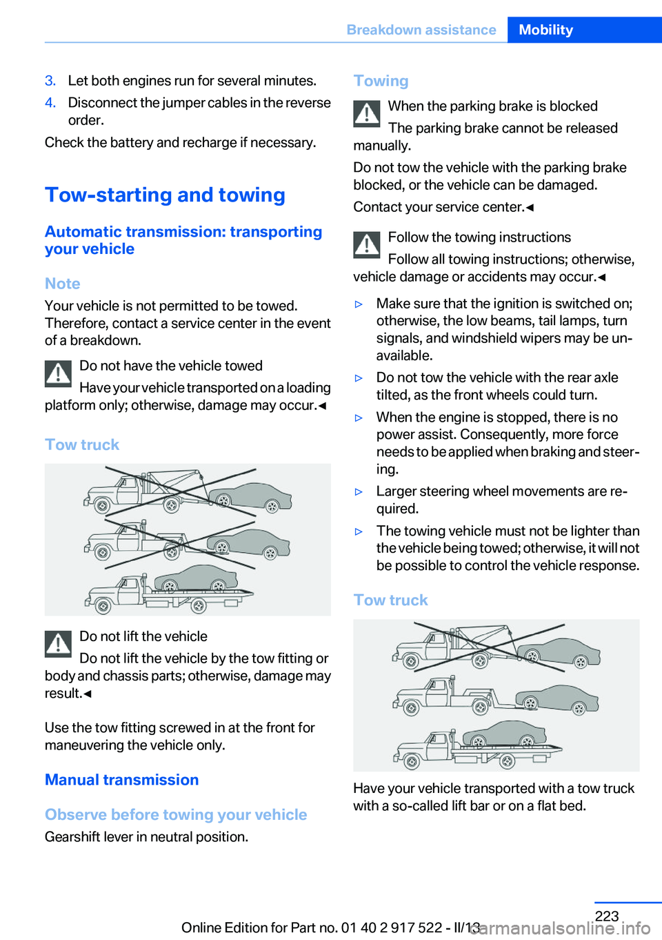
Tow truck
Do not lift the vehicle
Do not lift the vehicle by the tow fitting or
body and chassis parts; otherwise, damage may
result.◀
Use the tow fitting screwed in at the front for
maneuvering the vehicle only.
Manual transmission
Observe before towing your vehicle
Gearshift lever in neutral position.
Towing
When the parking brake is blocked
The parking brake cannot be released
manually.
Do not tow the vehicle with the parking brake
blocked, or the vehicle can be damaged.
Contact your service center.◀
Follow the towing instructions
Follow all towing instructions; otherwise,
vehicle damage or accidents may occur.◀▷Make sure that the ignition is switched on;
otherwise, the low beams, tail lamps, turn
signals, and windshield wipers may be un‐
available.▷Do not tow the vehicle with the rear axle
tilted, as the front wheels could turn.▷When the engine is stopped, there is no
power assist. Consequently, more force
needs to be applied when braking and steer‐
ing.▷Larger steering wheel movements are re‐
quired.▷The towing vehicle must not be lighter than
the vehicle being towed; otherwise, it will not
be possible to control the vehicle response.
Tow truck
Have your vehicle transported with a tow truck
with a so-called lift bar or on a flat bed.
Seite 223Breakdown assistanceMobility223
Online Edition for Part no. 01 40 2 917 522 - II/13
Page 233 of 246
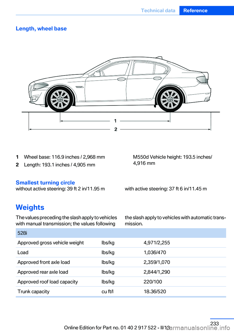
Length, wheel base1Wheel base: 116.9 inches / 2,968 mm2Length: 193.1 inches / 4,905 mmM550d Vehicle height: 193.5 inches/
4,916 mm
Smallest turning circle
without active steering: 39 ft 2 in/11.95 mwith active steering: 37 ft 6 in/11.45 m
Weights
The values preceding the slash apply to vehicles
with manual transmission; the values followingthe slash apply to vehicles with automatic trans‐
mission. 528iApproved gross vehicle weightlbs/kg4,971/2,255Loadlbs/kg1,036/470Approved front axle loadlbs/kg2,359/1,070Approved rear axle loadlbs/kg2,844/1,290Approved roof load capacitylbs/kg220/100Trunk capacitycu ft/l18.36/520Seite 233Technical dataReference233
Online Edition for Part no. 01 40 2 917 522 - II/13
Page 236 of 246
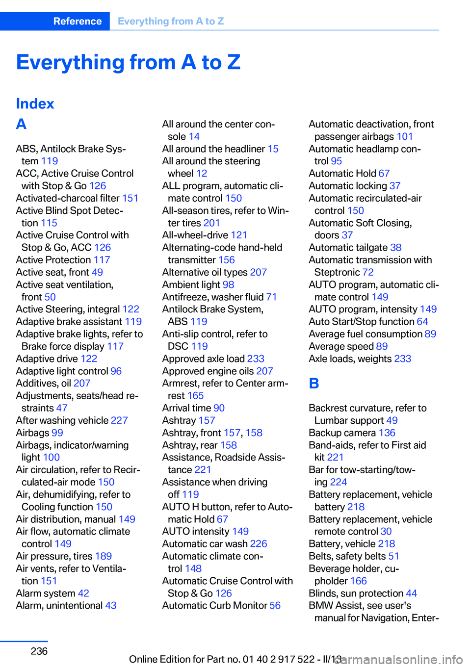
Everything from A to Z
IndexA
ABS, Antilock Brake Sys‐ tem 119
ACC, Active Cruise Control with Stop & Go 126
Activated-charcoal filter 151
Active Blind Spot Detec‐ tion 115
Active Cruise Control with Stop & Go, ACC 126
Active Protection 117
Active seat, front 49
Active seat ventilation, front 50
Active Steering, integral 122
Adaptive brake assistant 119
Adaptive brake lights, refer to Brake force display 117
Adaptive drive 122
Adaptive light control 96
Additives, oil 207
Adjustments, seats/head re‐ straints 47
After washing vehicle 227
Airbags 99
Airbags, indicator/warning light 100
Air circulation, refer to Recir‐ culated-air mode 150
Air, dehumidifying, refer to Cooling function 150
Air distribution, manual 149
Air flow, automatic climate control 149
Air pressure, tires 189
Air vents, refer to Ventila‐ tion 151
Alarm system 42
Alarm, unintentional 43 All around the center con‐
sole 14
All around the headliner 15
All around the steering wheel 12
ALL program, automatic cli‐ mate control 150
All-season tires, refer to Win‐ ter tires 201
All-wheel-drive 121
Alternating-code hand-held transmitter 156
Alternative oil types 207
Ambient light 98
Antifreeze, washer fluid 71
Antilock Brake System, ABS 119
Anti-slip control, refer to DSC 119
Approved axle load 233
Approved engine oils 207
Armrest, refer to Center arm‐ rest 165
Arrival time 90
Ashtray 157
Ashtray, front 157, 158
Ashtray, rear 158
Assistance, Roadside Assis‐ tance 221
Assistance when driving off 119
AUTO H button, refer to Auto‐ matic Hold 67
AUTO intensity 149
Automatic car wash 226
Automatic climate con‐ trol 148
Automatic Cruise Control with Stop & Go 126
Automatic Curb Monitor 56 Automatic deactivation, front
passenger airbags 101
Automatic headlamp con‐ trol 95
Automatic Hold 67
Automatic locking 37
Automatic recirculated-air control 150
Automatic Soft Closing, doors 37
Automatic tailgate 38
Automatic transmission with Steptronic 72
AUTO program, automatic cli‐ mate control 149
AUTO program, intensity 149
Auto Start/Stop function 64
Average fuel consumption 89
Average speed 89
Axle loads, weights 233
B
Backrest curvature, refer to Lumbar support 49
Backup camera 136
Band-aids, refer to First aid kit 221
Bar for tow-starting/tow‐ ing 224
Battery replacement, vehicle battery 218
Battery replacement, vehicle remote control 30
Battery, vehicle 218
Belts, safety belts 51
Beverage holder, cu‐ pholder 166
Blinds, sun protection 44
BMW Assist, see user's manual for Navigation, Enter‐Seite 236ReferenceEverything from A to Z236
Online Edition for Part no. 01 40 2 917 522 - II/13
Page 240 of 246
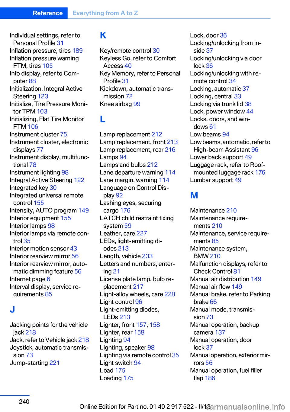
Individual settings, refer toPersonal Profile 31
Inflation pressure, tires 189
Inflation pressure warning FTM, tires 105
Info display, refer to Com‐ puter 88
Initialization, Integral Active Steering 123
Initialize, Tire Pressure Moni‐ tor TPM 103
Initializing, Flat Tire Monitor FTM 106
Instrument cluster 75
Instrument cluster, electronic displays 77
Instrument display, multifunc‐ tional 78
Instrument lighting 98
Integral Active Steering 122
Integrated key 30
Integrated universal remote control 155
Intensity, AUTO program 149
Interior equipment 155
Interior lamps 98
Interior lamps via remote con‐ trol 35
Interior motion sensor 43
Interior rearview mirror 56
Interior rearview mirror, auto‐ matic dimming feature 56
Internet page 6
Interval display, service re‐ quirements 85
J
Jacking points for the vehicle jack 218
Jack, refer to Vehicle jack 218
Joystick, automatic transmis‐ sion 73
Jump-starting 221 K
Key/remote control 30
Keyless Go, refer to Comfort Access 40
Key Memory, refer to Personal Profile 31
Kickdown, automatic trans‐ mission 72
Knee airbag 99
L
Lamp replacement 212
Lamp replacement, front 213
Lamp replacement, rear 216
Lamps 94
Lamps and bulbs 212
Lane departure warning 114
Lane margin, warning 114
Language on Control Dis‐ play 92
Lashing eyes, securing cargo 176
LATCH child restraint fixing system 59
Leather, care 227
LEDs, light-emitting di‐ odes 213
Length, vehicle 233
Letters and numbers, enter‐ ing 21
License plate lamp, bulb re‐ placement 217
Light-alloy wheels, care 228
Light control 96
Light-emitting diodes, LEDs 213
Lighter, front 157, 158
Lighter, rear 158
Lighting 94
Lighting, speaker 98
Lighting via remote control 35
Light switch 94
Load 175
Loading 175 Lock, door 36
Locking/unlocking from in‐ side 37
Locking/unlocking via door lock 36
Locking/unlocking with re‐ mote control 34
Locking, automatic 37
Locking, central 33
Locking via trunk lid 38
Lock, power window 44
Locks, doors, and win‐ dows 61
Low beams 94
Low beams, automatic, refer to High-beam Assistant 96
Lower back support 49
Luggage rack, refer to Roof- mounted luggage rack 176
Lumbar support 49
M
Maintenance 210
Maintenance require‐ ments 210
Maintenance, service require‐ ments 85
Maintenance system, BMW 210
Malfunction displays, refer to Check Control 81
Manual air distribution 149
Manual air flow 149
Manual brake, refer to Parking brake 66
Manual mode, transmis‐ sion 73
Manual operation, backup camera 137
Manual operation, door lock 37
Manual operation, exterior mir‐ rors 56
Manual operation, fuel filler flap 186 Seite 240ReferenceEverything from A to Z240
Online Edition for Part no. 01 40 2 917 522 - II/13