sensor BMW 535I XDRIVE GRAN TURISMO 2013 Owners Manual
[x] Cancel search | Manufacturer: BMW, Model Year: 2013, Model line: 535I XDRIVE GRAN TURISMO, Model: BMW 535I XDRIVE GRAN TURISMO 2013Pages: 240, PDF Size: 5.49 MB
Page 13 of 240
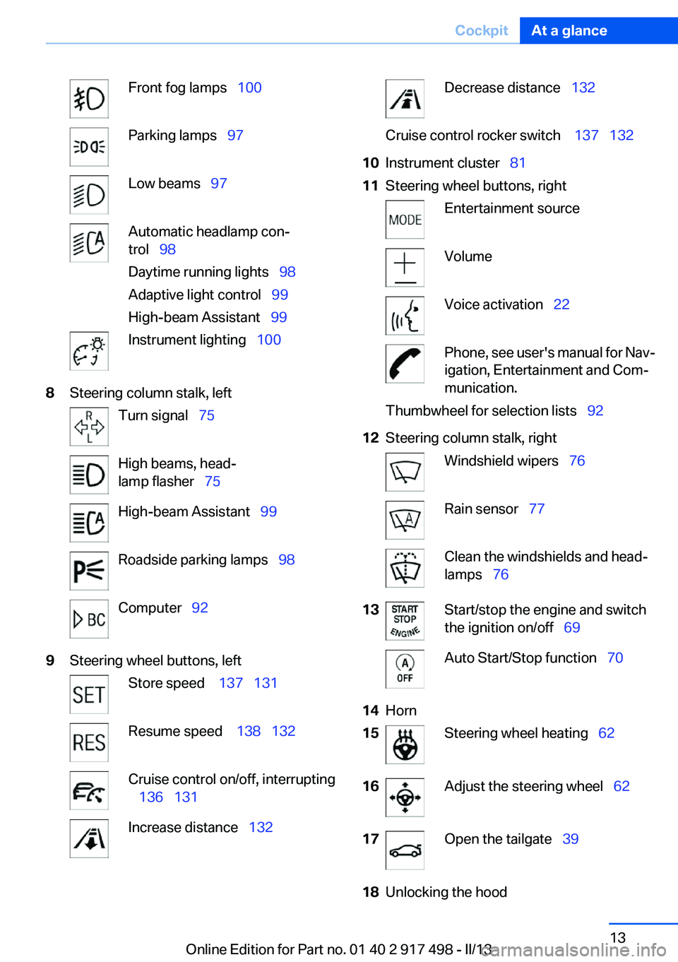
Front fog lamps‚Äā‚ÄÖ100Parking lamps‚Äā‚ÄÖ97Low beams‚Äā‚ÄÖ97Automatic headlamp con‚Äź
trol‚Äā‚ÄÖ 98
Daytime running lights‚Äā‚ÄÖ 98
Adaptive light control‚Äā‚ÄÖ 99
High-beam Assistant‚Äā‚ÄÖ 99Instrument lighting‚Äā‚ÄÖ1008Steering column stalk, leftTurn signal‚Äā‚ÄÖ75High beams, head‚Äź
lamp flasher‚Äā‚ÄÖ 75High-beam Assistant‚Äā‚ÄÖ 99Roadside parking lamps‚Äā‚ÄÖ 98Computer‚Äā‚ÄÖ929Steering wheel buttons, leftStore speed ‚Äā‚ÄÖ 137‚Äā‚ÄÖ131Resume speed ‚Äā‚ÄÖ 138‚Äā‚ÄÖ132Cruise control on/off, interrupting
‚Äā‚ÄÖ 136 ‚Äā‚ÄÖ131Increase distance‚Äā‚ÄÖ 132Decrease distance‚Äā‚ÄÖ 132Cruise control rocker switch ‚Äā‚ÄÖ 137‚Äā‚ÄÖ13210Instrument cluster‚Äā‚ÄÖ 8111Steering wheel buttons, rightEntertainment sourceVolumeVoice activation‚Äā‚ÄÖ22Phone, see user's manual for Nav‚Äź
igation, Entertainment and Com‚Äź
munication.Thumbwheel for selection lists‚Äā‚ÄÖ 9212Steering column stalk, rightWindshield wipers‚Äā‚ÄÖ76Rain sensor‚Äā‚ÄÖ77Clean the windshields and head‚Äź
lamps‚Äā‚ÄÖ 7613Start/stop the engine and switch
the ignition on/off‚Äā‚ÄÖ 69Auto Start/Stop function‚Äā‚ÄÖ 7014Horn15Steering wheel heating‚Äā‚ÄÖ6216Adjust the steering wheel‚Äā‚ÄÖ 6217Open the tailgate‚Äā‚ÄÖ3918Unlocking the hoodSeite 13CockpitAt a glance13
Online Edition for Part no. 01 40 2 917 498 - II/13
Page 42 of 240
Unlocking
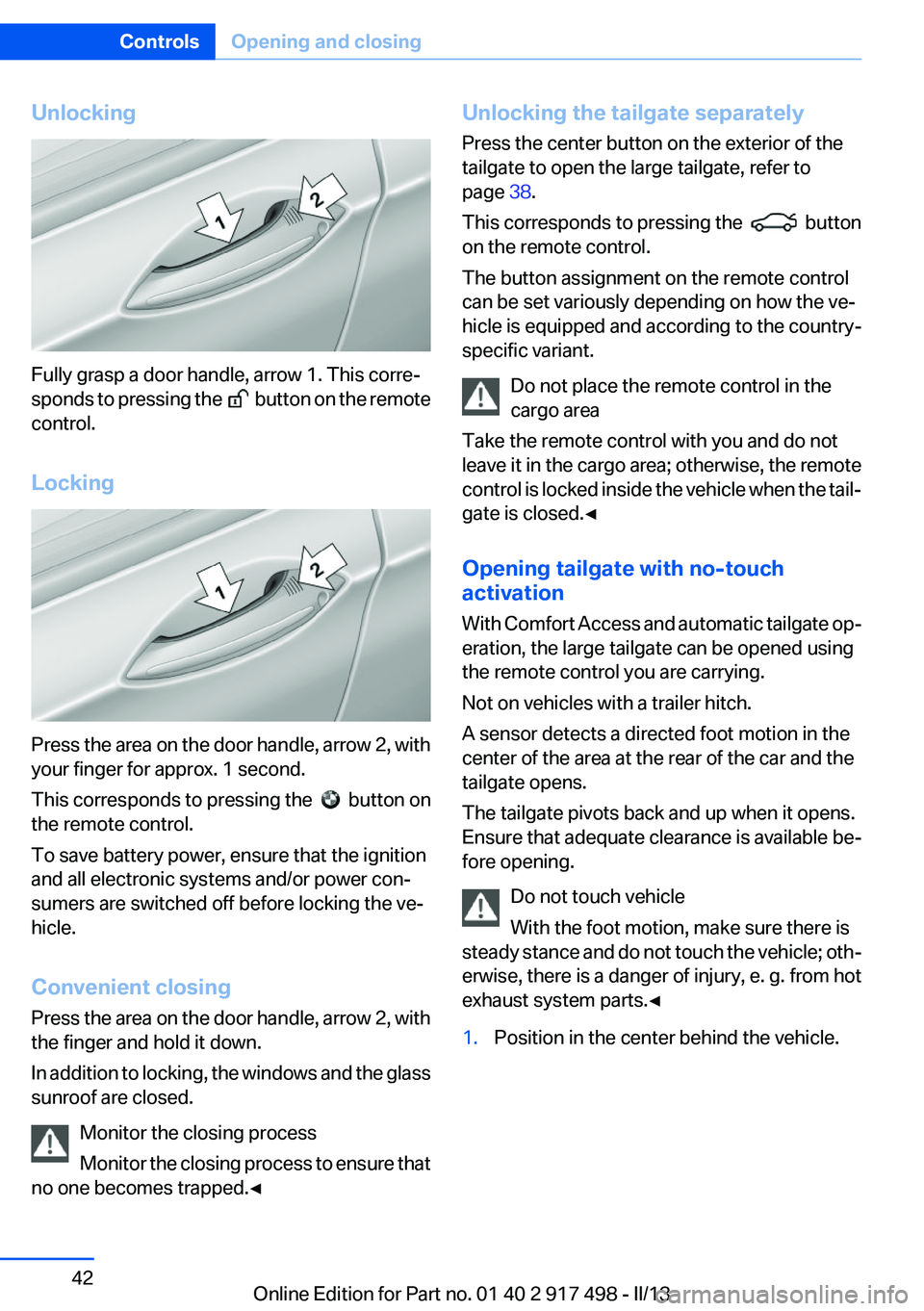
Fully grasp a door handle, arrow 1. This corre‚Äź
sponds to pressing the
button on the remote
control.
Locking
Press the area on the door handle, arrow 2, with
your finger for approx. 1 second.
This corresponds to pressing the
button on
the remote control.
To save battery power, ensure that the ignition
and all electronic systems and/or power con‚Äź
sumers are switched off before locking the ve‚Äź
hicle.
Convenient closing
Press the area on the door handle, arrow 2, with
the finger and hold it down.
In addition to locking, the windows and the glass
sunroof are closed.
Monitor the closing process
Monitor the closing process to ensure that
no one becomes trapped.‚óÄ
Unlocking the tailgate separately
Press the center button on the exterior of the
tailgate to open the large tailgate, refer to
page 38.
This corresponds to pressing the
button
on the remote control.
The button assignment on the remote control
can be set variously depending on how the ve‚Äź
hicle is equipped and according to the country-
specific variant.
Do not place the remote control in the
cargo area
Take the remote control with you and do not
leave it in the cargo area; otherwise, the remote
control is locked inside the vehicle when the tail‚Äź
gate is closed.‚óÄ
Opening tailgate with no-touch
activation
With Comfort Access and automatic tailgate op‚Äź
eration, the large tailgate can be opened using
the remote control you are carrying.
Not on vehicles with a trailer hitch.
A sensor detects a directed foot motion in the
center of the area at the rear of the car and the
tailgate opens.
The tailgate pivots back and up when it opens.
Ensure that adequate clearance is available be‚Äź
fore opening.
Do not touch vehicle
With the foot motion, make sure there is
steady stance and do not touch the vehicle; oth‚Äź
erwise, there is a danger of injury, e. g. from hot
exhaust system parts.‚óÄ
1.Position in the center behind the vehicle.Seite 42ControlsOpening and closing42
Online Edition for Part no. 01 40 2 917 498 - II/13
Page 43 of 240
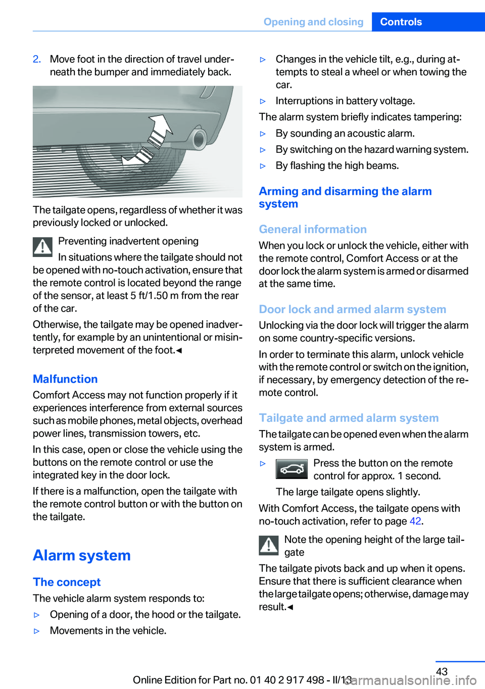
2.Move foot in the direction of travel under‚Äź
neath the bumper and immediately back.
The tailgate opens, regardless of whether it was
previously locked or unlocked.
Preventing inadvertent opening
In situations where the tailgate should not
be opened with no-touch activation, ensure that
the remote control is located beyond the range
of the sensor, at least 5 ft/1.50 m from the rear
of the car.
Otherwise, the tailgate may be opened inadver‚Äź
tently, for example by an unintentional or misin‚Äź
terpreted movement of the foot.‚óÄ
Malfunction
Comfort Access may not function properly if it
experiences interference from external sources
such as mobile phones, metal objects, overhead
power lines, transmission towers, etc.
In this case, open or close the vehicle using the
buttons on the remote control or use the
integrated key in the door lock.
If there is a malfunction, open the tailgate with
the remote control button or with the button on
the tailgate.
Alarm system
The concept
The vehicle alarm system responds to:
‚Ė∑Opening of a door, the hood or the tailgate.‚Ė∑Movements in the vehicle.‚Ė∑Changes in the vehicle tilt, e.g., during at‚Äź
tempts to steal a wheel or when towing the
car.‚Ė∑Interruptions in battery voltage.
The alarm system briefly indicates tampering:
‚Ė∑By sounding an acoustic alarm.‚Ė∑By switching on the hazard warning system.‚Ė∑By flashing the high beams.
Arming and disarming the alarm
system
General information
When you lock or unlock the vehicle, either with
the remote control, Comfort Access or at the
door lock the alarm system is armed or disarmed
at the same time.
Door lock and armed alarm system
Unlocking via the door lock will trigger the alarm
on some country-specific versions.
In order to terminate this alarm, unlock vehicle
with the remote control or switch on the ignition,
if necessary, by emergency detection of the re‚Äź
mote control.
Tailgate and armed alarm system
The tailgate can be opened even when the alarm
system is armed.
‚Ė∑Press the button on the remote
control for approx. 1 second.
The large tailgate opens slightly.
With Comfort Access, the tailgate opens with
no-touch activation, refer to page 42.
Note the opening height of the large tail‚Äź
gate
The tailgate pivots back and up when it opens.
Ensure that there is sufficient clearance when
the large tailgate opens; otherwise, damage may
result.‚óÄ
Seite 43Opening and closingControls43
Online Edition for Part no. 01 40 2 917 498 - II/13
Page 44 of 240
After the tailgate is closed, it is locked and moni‚Äź
tored again if the doors are locked. The hazard
warning system flashes once.
In some vehicle equipment variants, the tailgate
can only be opened using the remote control if
the vehicle was unlocked first.
Panic mode
You can trigger the alarm system if you find
yourself in a dangerous situation.
Press the button on the remote control
for at least 3 seconds.
To switch off the alarm: press any button.
Switching off the alarm‚Ė∑Unlock the vehicle using the remote control.‚Ė∑With Comfort Access: If you are carrying the
remote control with you, pull on the driver
side or front passenger side door handle.
Indicator lamp on the interior rear view
mirror
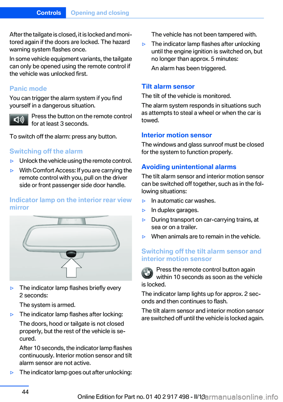
‚Ė∑The indicator lamp flashes briefly every
2 seconds:
The system is armed.‚Ė∑The indicator lamp flashes after locking:
The doors, hood or tailgate is not closed
properly, but the rest of the vehicle is se‚Äź
cured.
After 10 seconds, the indicator lamp flashes
continuously. Interior motion sensor and tilt
alarm sensor are not active.‚Ė∑The indicator lamp goes out after unlocking:The vehicle has not been tampered with.‚Ė∑The indicator lamp flashes after unlocking
until the engine ignition is switched on, but
no longer than approx. 5 minutes:
An alarm has been triggered.
Tilt alarm sensor
The tilt of the vehicle is monitored.
The alarm system responds in situations such
as attempts to steal a wheel or when the car is
towed.
Interior motion sensor
The windows and glass sunroof must be closed
for the system to function properly.
Avoiding unintentional alarms
The tilt alarm sensor and interior motion sensor
can be switched off together, such as in the fol‚Äź
lowing situations:
‚Ė∑In automatic car washes.‚Ė∑In duplex garages.‚Ė∑During transport on car-carrying trains, at
sea or on a trailer.‚Ė∑When animals are to remain in the vehicle.
Switching off the tilt alarm sensor and
interior motion sensor
Press the remote control button again
within 10 seconds as soon as the vehicle
is locked.
The indicator lamp lights up for approx. 2 sec‚Äź
onds and then continues to flash.
The tilt alarm sensor and interior motion sensor
are switched off until the vehicle is locked again.
Seite 44ControlsOpening and closing44
Online Edition for Part no. 01 40 2 917 498 - II/13
Page 77 of 240
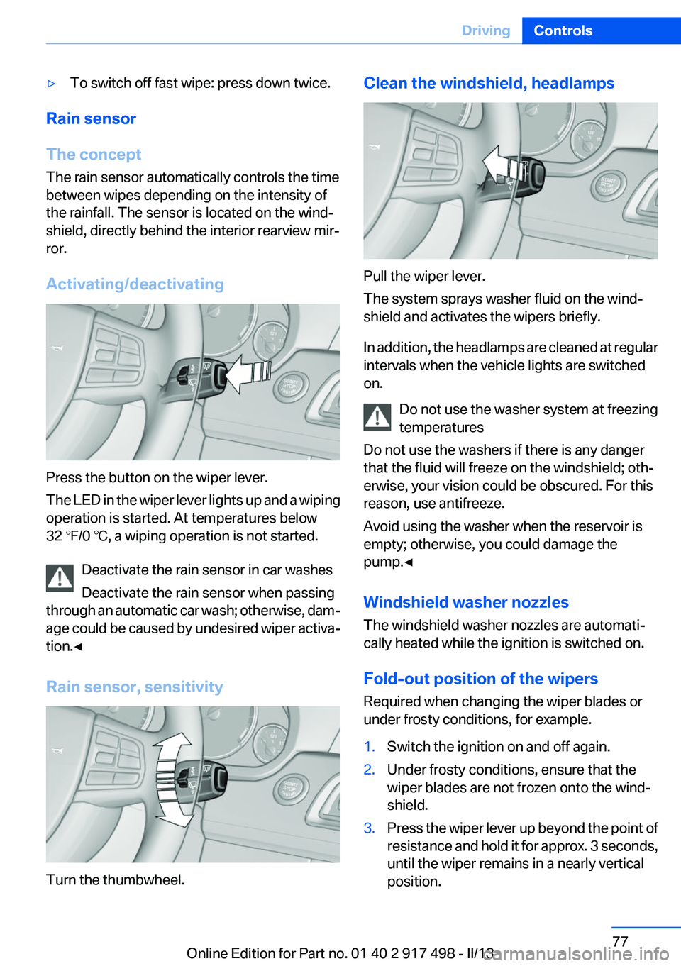
‚Ė∑To switch off fast wipe: press down twice.
Rain sensor
The concept
The rain sensor automatically controls the time
between wipes depending on the intensity of
the rainfall. The sensor is located on the wind‚Äź
shield, directly behind the interior rearview mir‚Äź
ror.
Activating/deactivating
Press the button on the wiper lever.
The LED in the wiper lever lights up and a wiping
operation is started. At temperatures below
32 ‚ĄČ/0 ‚ĄÉ, a wiping operation is not started.
Deactivate the rain sensor in car washes
Deactivate the rain sensor when passing
through an automatic car wash; otherwise, dam‚Äź
age could be caused by undesired wiper activa‚Äź
tion.‚óÄ
Rain sensor, sensitivity
Turn the thumbwheel.
Clean the windshield, headlamps
Pull the wiper lever.
The system sprays washer fluid on the wind‚Äź
shield and activates the wipers briefly.
In addition, the headlamps are cleaned at regular
intervals when the vehicle lights are switched
on.
Do not use the washer system at freezing
temperatures
Do not use the washers if there is any danger
that the fluid will freeze on the windshield; oth‚Äź
erwise, your vision could be obscured. For this
reason, use antifreeze.
Avoid using the washer when the reservoir is
empty; otherwise, you could damage the
pump.‚óÄ
Windshield washer nozzles
The windshield washer nozzles are automati‚Äź
cally heated while the ignition is switched on.
Fold-out position of the wipers
Required when changing the wiper blades or
under frosty conditions, for example.
1.Switch the ignition on and off again.2.Under frosty conditions, ensure that the
wiper blades are not frozen onto the wind‚Äź
shield.3.Press the wiper lever up beyond the point of
resistance and hold it for approx. 3 seconds,
until the wiper remains in a nearly vertical
position.Seite 77DrivingControls77
Online Edition for Part no. 01 40 2 917 498 - II/13
Page 90 of 240
Detailed information on service
requirements
More information on the scope of service re‚Äź
quired can be displayed on the Control Display.1."Vehicle Info"2."Vehicle status"3. "Service required"
Required maintenance procedures and le‚Äź
gally mandated inspections are displayed.4.Select an entry to call up detailed informa‚Äź
tion.
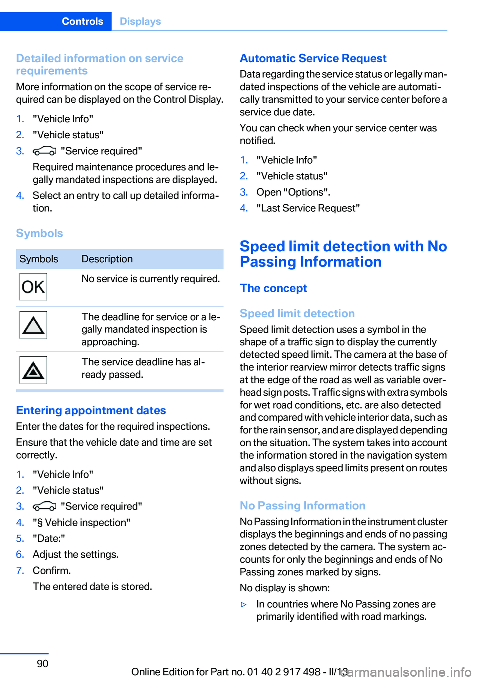
Symbols
SymbolsDescriptionNo service is currently required.The deadline for service or a le‚Äź
gally mandated inspection is
approaching.The service deadline has al‚Äź
ready passed.
Entering appointment dates
Enter the dates for the required inspections.
Ensure that the vehicle date and time are set
correctly.
1."Vehicle Info"2."Vehicle status"3. "Service required"4."§ Vehicle inspection"5."Date:"6.Adjust the settings.7.Confirm.
The entered date is stored.Automatic Service Request
Data regarding the service status or legally man‚Äź
dated inspections of the vehicle are automati‚Äź
cally transmitted to your service center before a
service due date.
You can check when your service center was
notified.1."Vehicle Info"2."Vehicle status"3.Open "Options".4."Last Service Request"
Speed limit detection with No
Passing Information
The concept
Speed limit detection
Speed limit detection uses a symbol in the
shape of a traffic sign to display the currently
detected speed limit. The camera at the base of
the interior rearview mirror detects traffic signs
at the edge of the road as well as variable over‚Äź
head sign posts. Traffic signs with extra symbols
for wet road conditions, etc. are also detected
and compared with vehicle interior data, such as
for the rain sensor, and are displayed depending
on the situation. The system takes into account
the information stored in the navigation system
and also displays speed limits present on routes
without signs.
No Passing Information
No Passing Information in the instrument cluster
displays the beginnings and ends of no passing
zones detected by the camera. The system ac‚Äź
counts for only the beginnings and ends of No
Passing zones marked by signs.
No display is shown:
‚Ė∑In countries where No Passing zones are
primarily identified with road markings.Seite 90ControlsDisplays90
Online Edition for Part no. 01 40 2 917 498 - II/13
Page 98 of 240
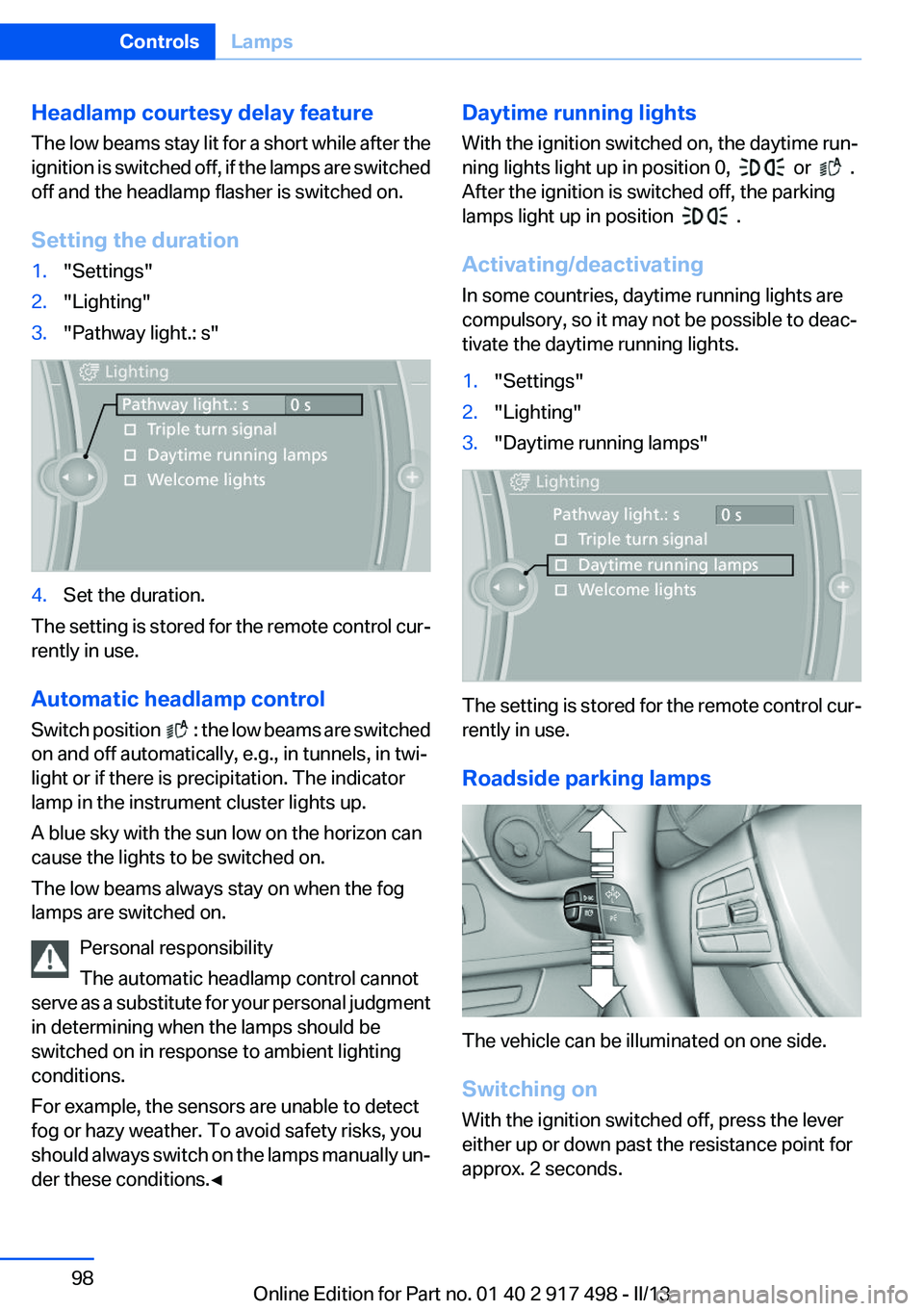
Headlamp courtesy delay feature
The low beams stay lit for a short while after the
ignition is switched off, if the lamps are switched
off and the headlamp flasher is switched on.
Setting the duration1."Settings"2."Lighting"3."Pathway light.: s"4.Set the duration.
The setting is stored for the remote control cur‚Äź
rently in use.
Automatic headlamp control
Switch position
: the low beams are switched
on and off automatically, e.g., in tunnels, in twi‚Äź
light or if there is precipitation. The indicator
lamp in the instrument cluster lights up.
A blue sky with the sun low on the horizon can
cause the lights to be switched on.
The low beams always stay on when the fog
lamps are switched on.
Personal responsibility
The automatic headlamp control cannot
serve as a substitute for your personal judgment
in determining when the lamps should be
switched on in response to ambient lighting
conditions.
For example, the sensors are unable to detect
fog or hazy weather. To avoid safety risks, you
should always switch on the lamps manually un‚Äź
der these conditions.‚óÄ
Daytime running lights
With the ignition switched on, the daytime run‚Äź
ning lights light up in position 0,
or .
After the ignition is switched off, the parking
lamps light up in position
.
Activating/deactivating
In some countries, daytime running lights are
compulsory, so it may not be possible to deac‚Äź
tivate the daytime running lights.
1."Settings"2."Lighting"3."Daytime running lamps"
The setting is stored for the remote control cur‚Äź
rently in use.
Roadside parking lamps
The vehicle can be illuminated on one side.
Switching on
With the ignition switched off, press the lever
either up or down past the resistance point for
approx. 2 seconds.
Seite 98ControlsLamps98
Online Edition for Part no. 01 40 2 917 498 - II/13
Page 99 of 240
Switching off
Briefly press the lever to the resistance point in
the opposite direction.
Adaptive light control
The concept
Adaptive Light Control is a variable headlamp
control system that enables dynamic illumina‚Äź
tion of the road surface.
Depending on the steering angle and other pa‚Äź
rameters, the light from the headlamp follows
the course of the road.
In tight curves, e.g., on mountainous roads or
when turning, an additional, corner-illuminating
lamp is switched on that lights up the inside of
the curve when the vehicle is moving below a
certain speed.
Activating
Switch position
with the ignition switched
on.
The turning lamps are automatically switched
on depending on the steering angle or the use
of turn signals.
To avoid blinding oncoming traffic, the Adaptive
Light Control does not swivel to the driver's side
when the vehicle is at a standstill.
When driving in reverse, only the turning lamp is
active.
Self-leveling headlights
The self-leveling headlights feature adapts the
light distribution to the contours of the road.
The light distribution is lowered on hilltops to
avoid blinding oncoming traffic and tilted in de‚Äź
pressions to increase visibility.
Malfunction
A Check Control message is displayed.
Adaptive light control is malfunctioning or has
failed. Have the system checked as soon as pos‚Äź
sible.
High-beam Assistant
The concept
When the low beams are switched on, this sys‚Äź
tem automatically switches the high beams on
and off. The procedure is controlled by a sensor
on the front of the interior rearview mirror. The
assistant ensures that the high beams are
switched on whenever the traffic situation al‚Äź
lows. The driver can intervene at any time and
switch the high beams on and off as usual.
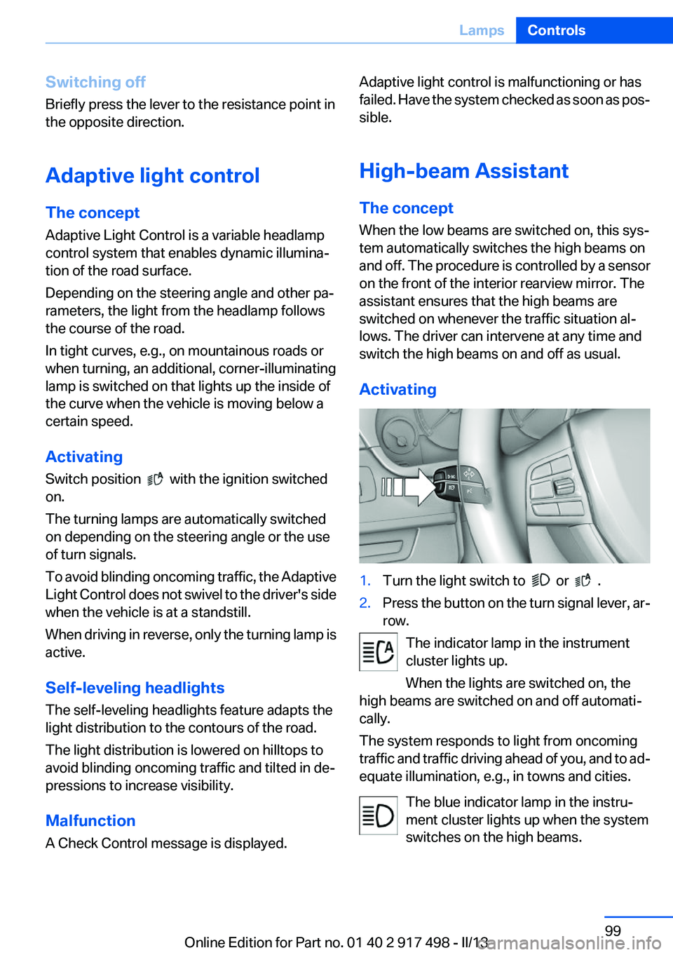
Activating1.Turn the light switch to or .2.Press the button on the turn signal lever, ar‚Äź
row.
The indicator lamp in the instrument
cluster lights up.
When the lights are switched on, the
high beams are switched on and off automati‚Äź
cally.
The system responds to light from oncoming
traffic and traffic driving ahead of you, and to ad‚Äź
equate illumination, e.g., in towns and cities.
The blue indicator lamp in the instru‚Äź
ment cluster lights up when the system
switches on the high beams.
Seite 99LampsControls99
Online Edition for Part no. 01 40 2 917 498 - II/13
Page 107 of 240
braking distance, and altered self-steering
properties. Adjust your driving style accord‚Äź
ingly. Avoid abrupt steering maneuvers or driv‚Äź
ing over obstacles, e.g., curbs, potholes, etc.
Because the possible driving distance depends
on how the vehicle is used during the trip, the
actual distance may be smaller or greater de‚Äź
pending on the driving speed, road conditions,
external temperature, cargo load, etc.
Continued driving with a flat tire
Drive moderately and do not exceed a
speed of 50 mph/80 km/h.
A loss of tire inflation pressure results in a
change in the handling characteristics, e.g., re‚Äź
duced lane stability during braking, a longer
braking distance and altered self-steering prop‚Äź
erties.‚óÄ
Final tire failure
Vibrations or loud noises while driving can
indicate the final failure of the tire. Reduce speed
and stop; otherwise, pieces of the tire could
come loose and cause an accident. Do not con‚Äź
tinue driving, and contact your service center. ‚óÄ
Tire Pressure Monitor TPM
The concept
The system monitors tire pressure in the four
mounted tires. The system warns you if there is
a significant loss of pressure in one or more tires.
For this purpose, sensors in the tire valves
measure the tire pressure and tire temperature.
Hints Tire damage due to external factors
Sudden tire damage caused by external
influences cannot be indicated in advance.‚óÄ
Pay attention to the other information and indi‚Äź
cations under Tire inflation pressure, refer to
page 191, as well when using the system.Functional requirements
The system must have been reset with the cor‚Äź
rect tire inflation pressure; otherwise, reliable
signaling of tire pressure loss is not ensured.
Reset the system again after each correction of
the tire inflation pressure and after every tire or
wheel change.
Always use wheels with TPM electronics to en‚Äź
sure that the system will operate properly.
Status display
The current status of the Tire Pressure Monitor
TPM can be displayed on the Control Display,
e.g., whether or not the TPM is active.1."Vehicle Info"2."Vehicle status"3. "Tire Pressure Monitor - TPM"
The status is displayed.
Status display
The tire and system status is indicated by the
color of the tires and a text message on the Con‚Äź
trol Display.
All wheels green
System is active and will issue a warning relative
to the tire inflation pressures stored during the
last reset.
One wheel is yellow
A flat tire or major drop in inflation pressure in
the indicated tire.
All wheels are yellow
A flat tire or major drop in inflation pressure in
several tires.
Wheels, gray
The system cannot detect a flat tire. Reasons for
this may be:
‚Ė∑The system is being reset.‚Ė∑Malfunction.Seite 107SafetyControls107
Online Edition for Part no. 01 40 2 917 498 - II/13
Page 110 of 240
‚Ė∑A wheel without TPM electronics is fitted:
have the service center check it if necessary.‚Ė∑Malfunction: have the system checked by
your service center.‚Ė∑TPM was unable to complete the reset. Re‚Äź
set the system again.‚Ė∑Disturbance by systems or devices with the
same radio frequency: after leaving the area
of the disturbance, the system automatically
becomes active again.
Declaration according to NHTSA/
FMVSS 138 Tire Pressure Monitoring
System
Each tire, including the spare (if provided)
should be checked monthly when cold and in‚Äź
flated to the inflation pressure recommended by
the vehicle manufacturer on the vehicle placard
or tire inflation pressure label. (If your vehicle has
tires of a different size than the size indicated on
the vehicle placard or tire inflation pressure la‚Äź
bel, you should determine the proper tire infla‚Äź
tion pressure for those tires.) As an added safety
feature, your vehicle has been equipped with a
tire pressure monitoring system (TPMS) that il‚Äź
luminates a low tire pressure telltale when one
or more of your tires is significantly under-in‚Äź
flated. Accordingly, when the low tire pressure
telltale illuminates, you should stop and check
your tires as soon as possible, and inflate them
to the proper pressure. Driving on a significantly
under-inflated tire causes the tire to overheat
and can lead to tire failure. Under-inflation also
reduces fuel efficiency and tire tread life, and
may affect the vehicle's handling and stopping
ability. Please note that the TPMS is not a sub‚Äź
stitute for proper tire maintenance, and it is the
driver's responsibility to maintain correct tire
pressure, even if under-inflation has not reached
the level to trigger illumination of the TPMS low
tire pressure telltale. Your vehicle has also been
equipped with a TPMS malfunction indicator to
indicate when the system is not operating prop‚Äź
erly. The TPMS malfunction indicator is com‚Äź
bined with the low tire pressure telltale. When
the system detects a malfunction, the telltale will
flash for approximately one minute and then re‚Äź
main continuously illuminated. This sequence
will continue upon subsequent vehicle start-ups
as long as the malfunction exists. When the mal‚Äź
function indicator is illuminated, the system may
not be able to detect or signal low tire pressure
as intended. TPMS malfunctions may occur for
a variety of reasons, including the installation of
replacement or alternate tires or wheels on the
vehicle that prevent the TPMS from functioning
properly. Always check the TPMS malfunction
telltale after replacing one or more tires or
wheels on your vehicle to ensure that the re‚Äź
placement or alternate tires and wheels allow
the TPMS to continue to function properly.
Collision warning with
braking function
The concept
If the vehicle is equipped with Active Cruise
Control with Stop & Go, the collision warning is
controlled via the cruise control radar sensor.
The system issues a two-phase warning of a
danger of collision at speeds above approx.
10 mph/15 km/h. The time of these warnings
may vary depending on the current driving sit‚Äź
uation.
The collision warning is available even if cruise
control has been deactivated.
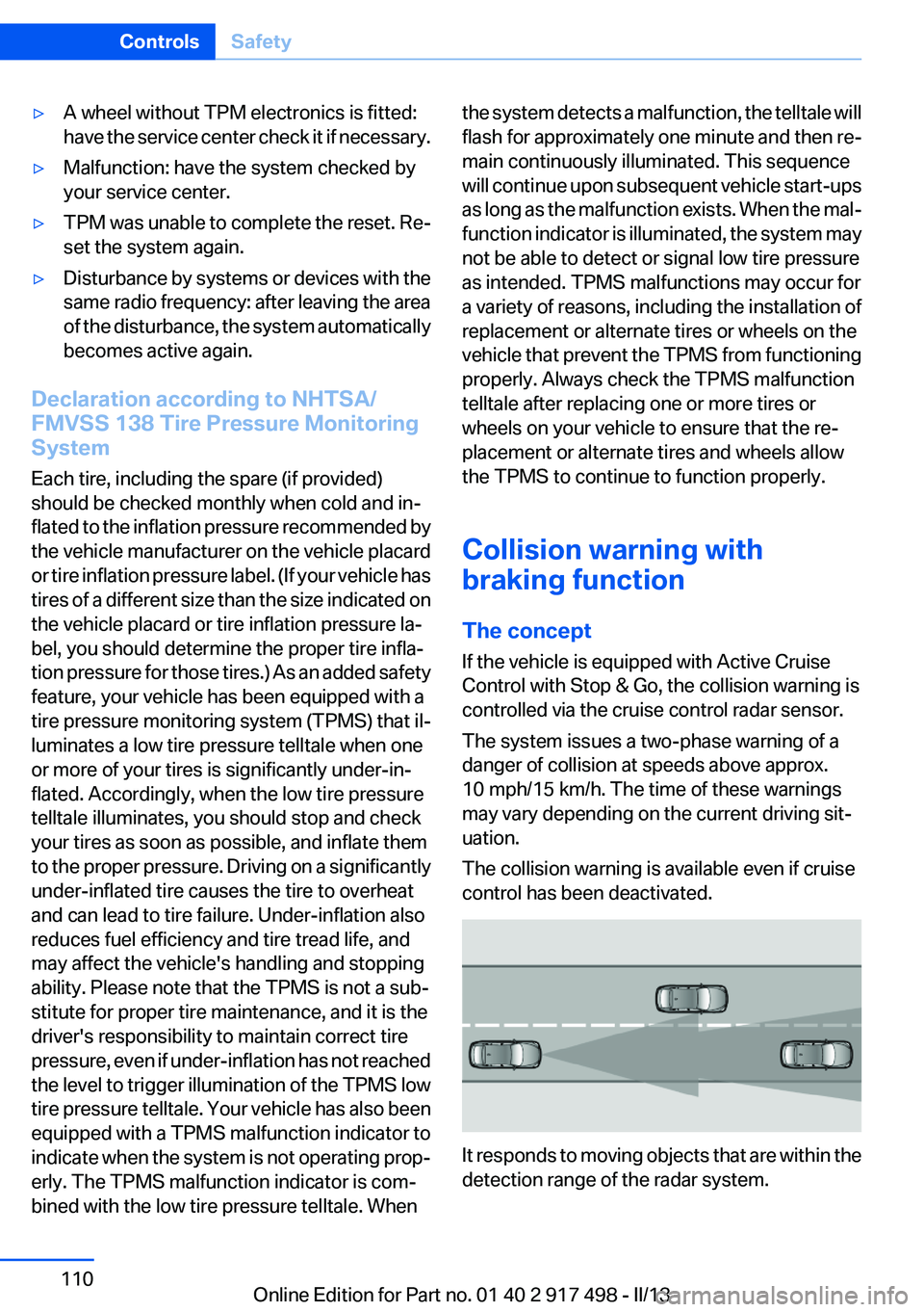
It responds to moving objects that are within the
detection range of the radar system.
Seite 110ControlsSafety110
Online Edition for Part no. 01 40 2 917 498 - II/13