rear entertainment BMW 535I XDRIVE GT 2011 F07 User Guide
[x] Cancel search | Manufacturer: BMW, Model Year: 2011, Model line: 535I XDRIVE GT, Model: BMW 535I XDRIVE GT 2011 F07Pages: 297, PDF Size: 8.59 MB
Page 59 of 297
Rear
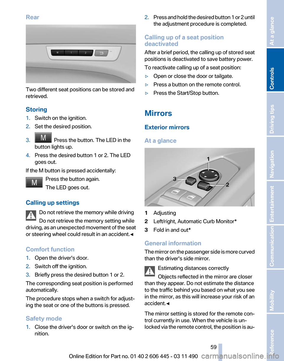
Two different seat positions can be stored and
retrieved.
Storing
1.
Switch on the ignition.
2. Set the desired position.
3. Press the button. The LED in the
button lights up.
4. Press the desired button 1 or 2. The LED
goes out.
If the M button is pressed accidentally: Press the button again.
The LED goes out.
Calling up settings Do not retrieve the memory while driving
Do not retrieve the memory setting while
driving,
as an unexpected movement of the seat
or steering wheel could result in an accident.◀
Comfort function
1. Open the driver's door.
2. Switch off the ignition.
3. Briefly press the desired button 1 or 2.
The corresponding seat position is performed
automatically.
The procedure stops when a switch for adjust‐
ing the seat or one of the buttons is pressed.
Safety mode
1. Close the driver's door or switch on the ig‐
nition. 2.
Press and hold the desired button 1 or 2 until
the adjustment procedure is completed.
Calling up of a seat position
deactivated
After
a brief period, the calling up of stored seat
positions is deactivated to save battery power.
To reactivate calling up of a seat position:
▷ Open or close the door or tailgate.
▷ Press a button on the remote control.
▷ Press the Start/Stop button.
Mirrors
Exterior mirrors
At a glance 1
Adjusting
2 Left/right, Automatic Curb Monitor*
3 Fold in and out*
General information
The
mirror on the passenger side is more curved
than the driver's side mirror.
Estimating distances correctly
Objects reflected in the mirror are closer
than they appear. Do not estimate the distance
to the traffic behind you based on what you see
in the mirror, as this will increase your risk of an
accident.◀
The mirror setting is stored for the remote con‐
trol currently in use. When the vehicle is un‐
locked via the remote control, the position is au‐ Seite 59
59Online Edition for Part no. 01 40 2 606 445 - 03 11 490
Reference Mobility Communication Entertainment Navigation Driving tips
Controls At a glance
Page 61 of 297
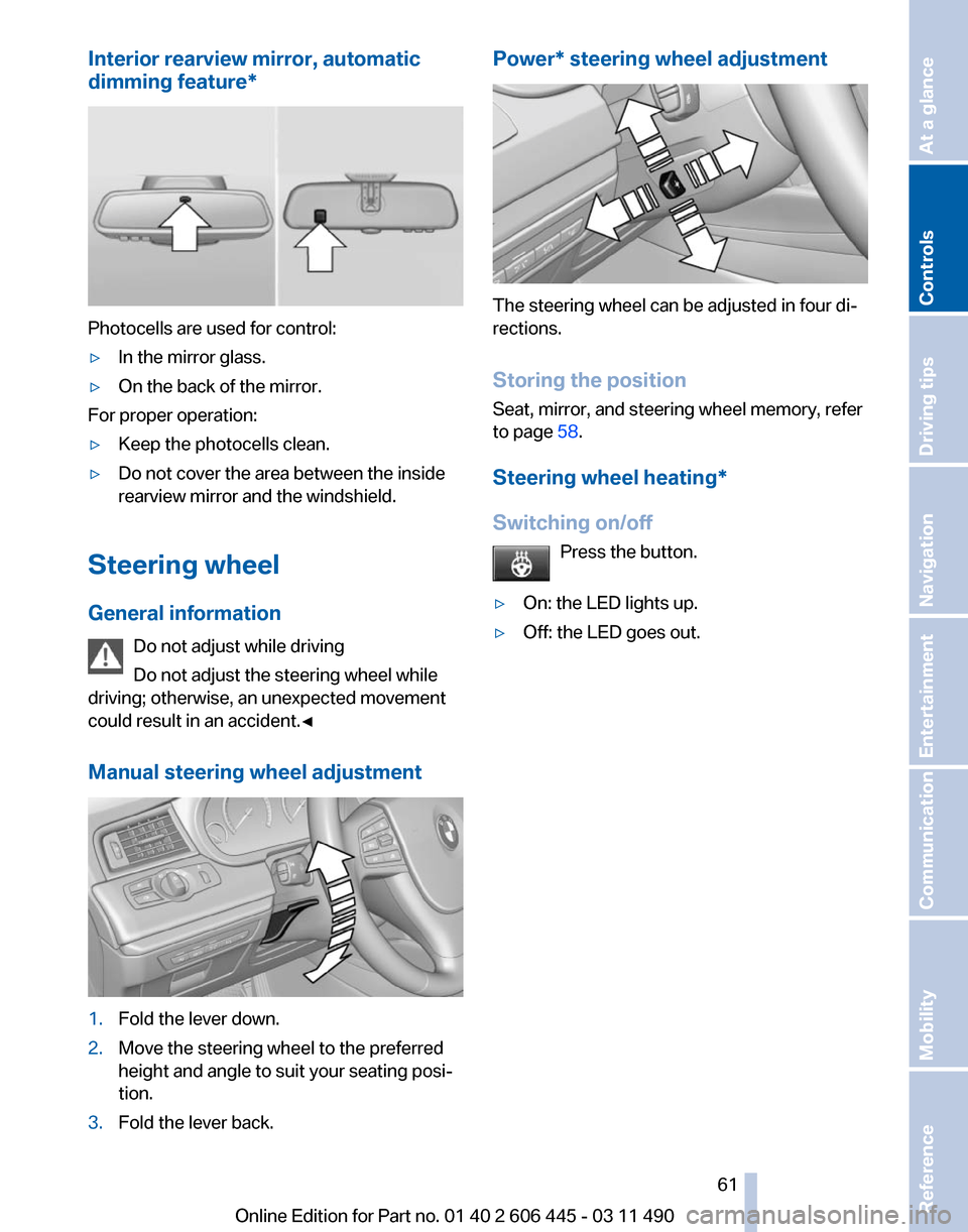
Interior rearview mirror, automatic
dimming feature
*Photocells are used for control:
▷
In the mirror glass.
▷ On the back of the mirror.
For proper operation:
▷ Keep the photocells clean.
▷ Do not cover the area between the inside
rearview mirror and the windshield.
Steering wheel
General information Do not adjust while driving
Do not adjust the steering wheel while
driving; otherwise, an unexpected movement
could result in an accident.◀
Manual steering wheel adjustment 1.
Fold the lever down.
2. Move the steering wheel to the preferred
height and angle to suit your seating posi‐
tion.
3. Fold the lever back. Power* steering wheel adjustment
The steering wheel can be adjusted in four di‐
rections.
Storing the position
Seat, mirror, and steering wheel memory, refer
to page
58.
Steering wheel heating
*
Switching on/off Press the button.
▷ On: the LED lights up.
▷ Off: the LED goes out. Seite 61
61Online Edition for Part no. 01 40 2 606 445 - 03 11 490
Reference Mobility Communication Entertainment Navigation Driving tips
Controls At a glance
Page 63 of 297
Backrest width*
Before
installing a child restraint fixing system in
the front passenger seat, open the backrest
width completely. Do not change the backrest
width again and do not call up a memory posi‐
tion.
Backrest width for the child seat
Before installing a child restraint fixing
system in the front passenger seat, the backrest
width must be opened completely. Do not
change the adjustment after this; otherwise, the
stability of the child seat will be reduced.◀
Child seat security The rear safety belts and the front passenger
safety belt can be locked against pulling out for
mounting the child restraint fixing systems.
Locking the safety belt
1.
Pull out the belt webbing completely.
2. Secure the child restraint fixing system with
the belt.
3. Allow the belt webbing to be pulled in and
pull it taut against the child restraint fixing
system. The safety belt is locked.
Unlocking the safety belt
1. Unbuckle the belt buckle.
2. Remove the child restraint fixing system.
3. Allow the belt webbing to be pulled in com‐
pletely. LATCH child restraint fixing
system
LATCH:
Lower Anchors and Tether for Children.
Note Manufacturer's information for LATCH
child restraint fixing systems
To mount and use the LATCH child restraint fix‐
ing systems, observe the operating and safety
information from the system manufacturer; oth‐
erwise, the level of protection may be reduced.◀
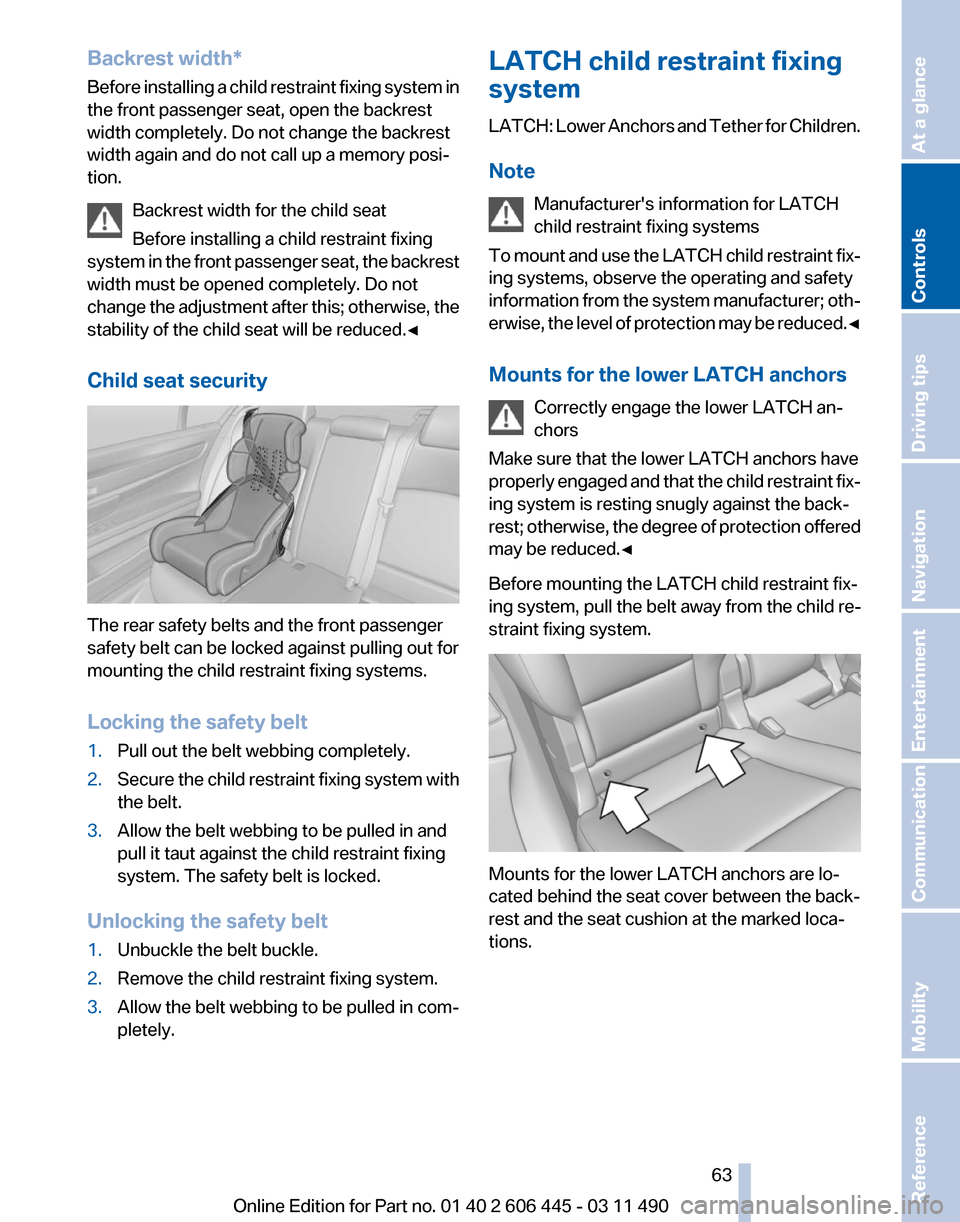
Mounts for the lower LATCH anchors
Correctly engage the lower LATCH an‐
chors
Make sure that the lower LATCH anchors have
properly engaged and that the child restraint fix‐
ing system is resting snugly against the back‐
rest; otherwise, the degree of protection offered
may be reduced.◀
Before mounting the LATCH child restraint fix‐
ing system, pull the belt away from the child re‐
straint fixing system. Mounts for the lower LATCH anchors are lo‐
cated behind the seat cover between the back‐
rest and the seat cushion at the marked loca‐
tions. Seite 63
63Online Edition for Part no. 01 40 2 606 445 - 03 11 490
Reference Mobility Communication Entertainment Navigation Driving tips
Controls At a glance
Page 65 of 297
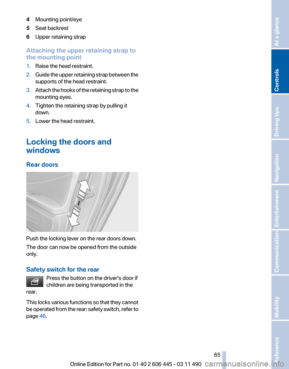
4
Mounting point/eye
5 Seat backrest
6 Upper retaining strap
Attaching the upper retaining strap to
the mounting point
1. Raise the head restraint.
2. Guide the upper retaining strap between the
supports of the head restraint.
3. Attach the hooks of the retaining strap to the
mounting eyes.
4. Tighten the retaining strap by pulling it
down.
5. Lower the head restraint.
Locking the doors and
windows
Rear doors Push the locking lever on the rear doors down.
The door can now be opened from the outside
only.
Safety switch for the rear
Press the button on the driver's door if
children are being transported in the
rear.
This
locks various functions so that they cannot
be operated from the rear: safety switch, refer to
page 46. Seite 65
65Online Edition for Part no. 01 40 2 606 445 - 03 11 490
Reference Mobility Communication Entertainment Navigation Driving tips
Controls At a glance
Page 67 of 297
Before leaving the car with the engine running,
set
the parking brake and place the transmission
in position P or neutral to prevent the car from
moving.◀
Frequent starting in quick succession
Avoid repeated futile attempts at starting
the car and avoid starting the car frequently in
quick succession. Otherwise, the fuel is not
burned or is inadequately burned, and there is
the danger of overheating and damaging the
catalytic converter.◀
Do not wait for the engine to warm up while the
vehicle remains stationary. Start driving at mod‐
erate engine speeds.
Starting the engine
Press on the brake pedal and
press the Start/Stop button.
The engine is cranked until it
starts.
Engine stop
General information Take the remote control with you
Take the remote control with you when
leaving the vehicle so that children, for example,
cannot operate the windows and injure them‐
selves.◀
Set the parking brake and further secure
the vehicle as required
Set the parking brake firmly when parking; oth‐
erwise, the vehicle could roll. On steep upward
and downward inclines, further secure the vehi‐
cle, for example, by turning the steering wheel in
the direction of the curb. ◀
Before driving into a car wash
In order for the vehicle to be able to roll into a car
wash, heed the information regarding Washing
in automatic car washes, refer to page 269. Switching off the engine
1.
Engage transmission position P with the ve‐
hicle stopped.
2. Press the Start/Stop button.
The engine is switched off.
The radio ready state is switched on.
3. Set the parking brake.
Parking brake
The concept
The
parking brake is used to prevent the vehicle
from rolling when it is parked.
▷ Engine switched off: the parking brake acts
on the rear wheels.
▷ Engine running: the parking brake acts on
the disc brakes of the front and rear wheels
via the hydraulic brake system.
The parking brake can be set manually or auto‐
matically:
▷ Manual: by pulling and pushing the switch.
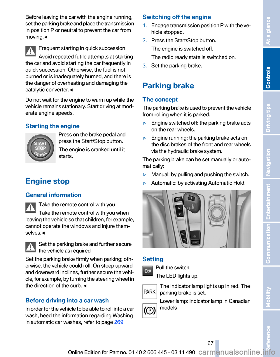
▷ Automatic: by activating Automatic Hold. Setting
Pull the switch.
The LED lights up.
The indicator lamp lights up in red. The
parking brake is set.
Lower lamp: indicator lamp in Canadian
models Seite 67
67Online Edition for Part no. 01 40 2 606 445 - 03 11 490
Reference Mobility Communication Entertainment Navigation Driving tips
Controls At a glance
Page 85 of 297
Lamps
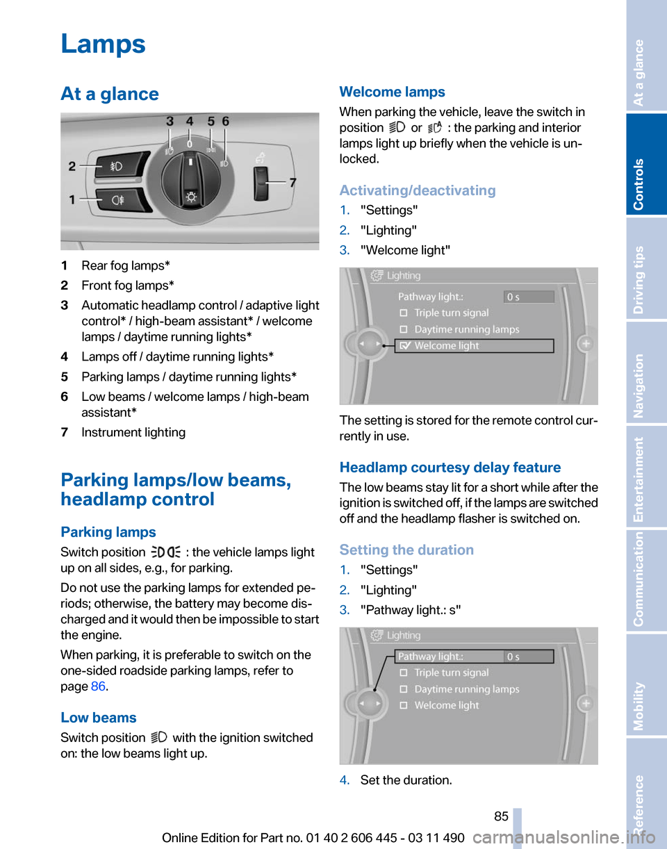
At a glance
1
Rear fog lamps*
2 Front fog lamps*
3 Automatic headlamp control / adaptive light
control* / high-beam assistant* / welcome
lamps / daytime running lights
*
4 Lamps off / daytime running lights*
5 Parking lamps / daytime running lights*
6 Low beams / welcome lamps / high-beam
assistant*
7 Instrument lighting
Parking lamps/low beams,
headlamp control
Parking lamps
Switch position : the vehicle lamps light
up on all sides, e.g., for parking.
Do not use the parking lamps for extended pe‐
riods; otherwise, the battery may become dis‐
charged
and it would then be impossible to start
the engine.
When parking, it is preferable to switch on the
one-sided roadside parking lamps, refer to
page 86.
Low beams
Switch position with the ignition switched
on: the low beams light up. Welcome lamps
When parking the vehicle, leave the switch in
position or : the parking and interior
lamps light up briefly when the vehicle is un‐
locked.
Activating/deactivating
1. "Settings"
2. "Lighting"
3. "Welcome light" The setting is stored for the remote control cur‐
rently in use.
Headlamp courtesy delay feature
The
low beams stay lit for a short while after the
ignition is switched off, if the lamps are switched
off and the headlamp flasher is switched on.
Setting the duration
1. "Settings"
2. "Lighting"
3. "Pathway light.: s" 4.
Set the duration.
Seite 85
85Online Edition for Part no. 01 40 2 606 445 - 03 11 490
Reference Mobility Communication Entertainment Navigation Driving tips
Controls At a glance
Page 87 of 297
To avoid blinding oncoming traffic, the adaptive
light control directs light towards the front pas‐
senger side when the vehicle is at a standstill.
When
driving in reverse, only the turning lamp is
active.
Self-leveling headlights
The self-leveling headlights feature adapts the
light distribution to the contours of the road.
The light distribution is lowered on hilltops to
avoid blinding oncoming traffic and tilted in de‐
pressions to increase visibility.
Malfunction
A Check Control message is displayed.
Adaptive light control is malfunctioning or has
failed. Have the system checked as soon as pos‐
sible.
High-beam Assistant*
The concept
When the low beams are switched on, this sys‐
tem automatically switches the high beams on
and off. The procedure is controlled by a sensor
on the front of the interior rearview mirror. The
assistant ensures that the high beams are
switched on whenever the traffic situation al‐
lows. The driver can intervene at any time and
switch the high beams on and off as usual.
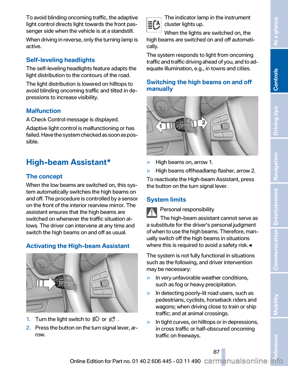
Activating the High-beam Assistant 1.
Turn the light switch to or .
2. Press the button on the turn signal lever, ar‐
row. The indicator lamp in the instrument
cluster lights up.
When the lights are switched on, the
high beams are switched on and off automati‐
cally.
The system responds to light from oncoming
traffic
and traffic driving ahead of you, and to ad‐
equate illumination, e.g., in towns and cities.
Switching the high beams on and off
manually ▷
High beams on, arrow 1.
▷ High beams off/headlamp flasher, arrow 2.
To reactivate the High-beam Assistant, press
the button on the turn signal lever.
System limits
Personal responsibility
The high-beam assistant cannot serve as
a substitute for the driver's personal judgment
of
when to use the high beams. Therefore, man‐
ually switch off the high beams in situations
where this is required to avoid a safety risk.◀
The system is not fully functional in situations
such as the following, and driver intervention
may be necessary:
▷ In very unfavorable weather conditions,
such as fog or heavy precipitation.
▷ In detecting poorly-lit road users, such as
pedestrians, cyclists, horseback riders and
wagons; when driving close to train or ship
traffic; and at animal crossings.
▷ In tight curves, on hilltops or in depressions,
in cross traffic or half-obscured oncoming
traffic on freeways. Seite 87
87Online Edition for Part no. 01 40 2 606 445 - 03 11 490
Reference Mobility Communication Entertainment Navigation Driving tips
Controls At a glance
Page 89 of 297
Safety
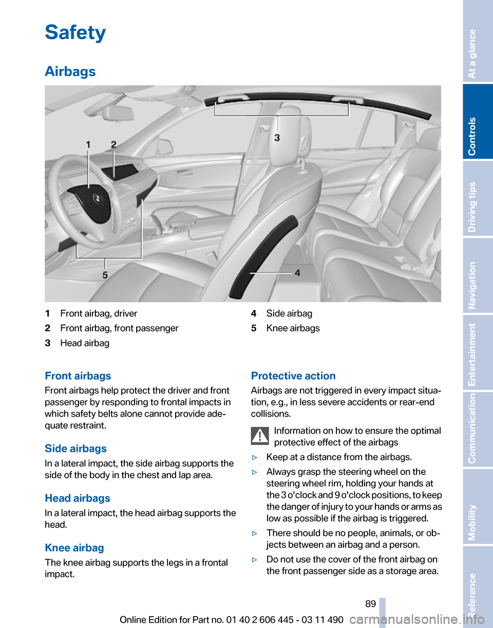
Airbags
1
Front airbag, driver
2 Front airbag, front passenger
3 Head airbag 4
Side airbag
5 Knee airbags
Front airbags
Front airbags help protect the driver and front
passenger by responding to frontal impacts in
which safety belts alone cannot provide ade‐
quate restraint.
Side airbags
In a lateral impact, the side airbag supports the
side of the body in the chest and lap area.
Head airbags
In
a lateral impact, the head airbag supports the
head.
Knee airbag
The knee airbag supports the legs in a frontal
impact. Protective action
Airbags are not triggered in every impact situa‐
tion, e.g., in less severe accidents or rear-end
collisions.
Information on how to ensure the optimal
protective effect of the airbags
▷ Keep at a distance from the airbags.
▷ Always grasp the steering wheel on the
steering wheel rim, holding your hands at
the
3 o'clock and 9 o'clock positions, to keep
the danger of injury to your hands or arms as
low as possible if the airbag is triggered.
▷ There should be no people, animals, or ob‐
jects between an airbag and a person.
▷ Do not use the cover of the front airbag on
the front passenger side as a storage area. Seite 89
89Online Edition for Part no. 01 40 2 606 445 - 03 11 490
Reference Mobility Communication Entertainment Navigation Driving tips
Controls At a glance
Page 91 of 297
Child restraint fixing system in the front
passenger seat
Before
transporting a child on the front passen‐
ger seat, see the safety notes and instructions
under Children on the front passenger seat.◀
Malfunction of the automatic
deactivation system
When transporting older children and adults, the
front passenger airbags may be deactivated in
certain sitting positions. In this case, the indica‐
tor lamp for the front passenger airbags lights
up.
In this case, change the sitting position so that
the front passenger airbags are activated and
the indicator lamp goes out.
If it is not possible to activate the airbags, have
the person sit in the rear.
To make sure that the occupied seat cushion
can be evaluated correctly
▷ Do not attach covers, cushions, ball mats or
other items to the front passenger seat un‐
less they are specifically recommended by
the manufacturer of your vehicle.
▷ Do not place any objects on the front pas‐
senger seat.
▷ Do not place objects under the seat that
could press against the seat from below.
Indicator lamp for the front passenger
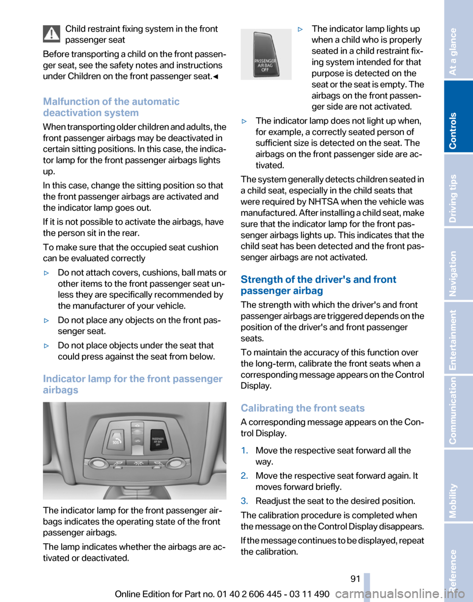
airbags The indicator lamp for the front passenger air‐
bags indicates the operating state of the front
passenger airbags.
The lamp indicates whether the airbags are ac‐
tivated or deactivated. ▷
The indicator lamp lights up
when a child who is properly
seated in a child restraint fix‐
ing system intended for that
purpose is detected on the
seat
or the seat is empty. The
airbags on the front passen‐
ger side are not activated.
▷ The indicator lamp does not light up when,
for example, a correctly seated person of
sufficient size is detected on the seat. The
airbags on the front passenger side are ac‐
tivated.
The system generally detects children seated in
a child seat, especially in the child seats that
were required by NHTSA when the vehicle was
manufactured.
After installing a child seat, make
sure that the indicator lamp for the front pas‐
senger airbags lights up. This indicates that the
child seat has been detected and the front pas‐
senger airbags are not activated.
Strength of the driver's and front
passenger airbag
The strength with which the driver's and front
passenger airbags are triggered depends on the
position of the driver's and front passenger
seats.
To maintain the accuracy of this function over
the long-term, calibrate the front seats when a
corresponding message appears on the Control
Display.
Calibrating the front seats
A corresponding message appears on the Con‐
trol Display.
1. Move the respective seat forward all the
way.
2. Move the respective seat forward again. It
moves forward briefly.
3. Readjust the seat to the desired position.
The calibration procedure is completed when
the
message on the Control Display disappears.
If the message continues to be displayed, repeat
the calibration. Seite 91
91Online Edition for Part no. 01 40 2 606 445 - 03 11 490
Reference Mobility Communication Entertainment Navigation Driving tips
Controls At a glance
Page 97 of 297
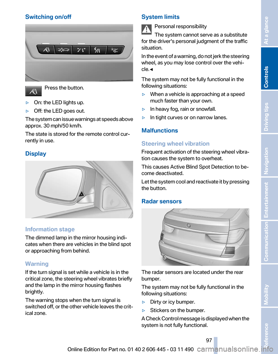
Switching on/off
Press the button.
▷ On: the LED lights up.
▷ Off: the LED goes out.
The system can issue warnings at speeds above
approx. 30 mph/50 km/h.
The state is stored for the remote control cur‐
rently in use.
Display Information stage
The dimmed lamp in the mirror housing indi‐
cates when there are vehicles in the blind spot
or approaching from behind.
Warning
If the turn signal is set while a vehicle is in the
critical zone, the steering wheel vibrates briefly
and the lamp in the mirror housing flashes
brightly.
The warning stops when the turn signal is
switched
off, or the other vehicle leaves the crit‐
ical zone. System limits
Personal responsibility
The system cannot serve as a substitute
for the driver's personal judgment of the traffic
situation.
In
the event of a warning, do not jerk the steering
wheel, as you may lose control over the vehi‐
cle.◀
The system may not be fully functional in the
following situations:
▷ When a vehicle is approaching at a speed
much faster than your own.
▷ In heavy fog, rain or snowfall.
▷ In tight curves or on narrow lanes.
Malfunctions
Steering wheel vibration
Frequent
activation of the steering wheel vibra‐
tion causes the system to overheat.
This causes Active Blind Spot Detection to be‐
come deactivated.
Let the system cool and reactivate it by pressing
the button.
Radar sensors The radar sensors are located under the rear
bumper.
The system may not be fully functional in the
following situations:
▷
Dirty or icy bumper.
▷ Stickers on the bumper.
A Check Control message is displayed when the
system is not fully functional. Seite 97
97Online Edition for Part no. 01 40 2 606 445 - 03 11 490
Reference Mobility Communication Entertainment Navigation Driving tips
Controls At a glance