replacing ignition lock BMW 540i 1997 E39 Workshop Manual
[x] Cancel search | Manufacturer: BMW, Model Year: 1997, Model line: 540i, Model: BMW 540i 1997 E39Pages: 1002
Page 360 of 1002
Downloaded from www.Manualslib.com manuals search engine
120-1 2
ignition System
Crankshaftspeedsensor
Crankshaft speed sensor, replacing (M52, M52 TU and
M54 engines)
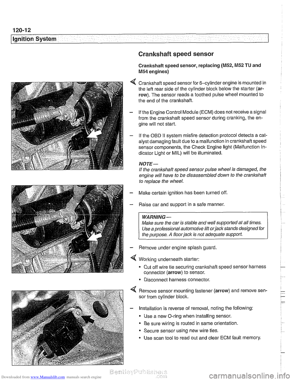
4 Crankshaft speed sensor for 6-cylinder engine is mounted in
the left rear side of the cylinder block below the starter (ar-
row). The sensor reads a toothed pulse wheel mounted to
the end of the crankshaft.
- if the Engine Control Module (ECM) does not receive a signal
from the crankshaft speed sensor during cranking, the en-
gine will not start.
- If the OBD II svstem misfire detection ~rotocol detects a cat- - - ~~
alysr oarnagin; faLlt oJe to a ma I-nclion in crandshafi speeo
sensor components. Ine Check Engine
lignr (Malfuncrion In-
dicator Light or MIL) will be illuminated.
NOTE-
If the crankshaft speed sensor pulse wheel is damaged, the
engine will have to be disassembled down to the crankshaft
to
reolace the wheel.
- Make certain ignition has been turned off.
- Raise car and support in a safe manner.
WARNING -
Make sure the car is stable and well supported at all times.
Use a professional automotive lift orjacltstands designed for
the ouroose.
A floor iaclc is not adequate support.
- Remove under engine splash guard
4 Working underneath starter:
Cut off wire tie securing crankshaft speed sensor harness
connector (arrow) to sensor.
* Disconnect harness connector.
4 Remove sensor mounting fastener (arrow) and remove sen-
sor from cylinder block.
- Installation is reverse of removal, noting the following:
Use a new O-ring when installing sensor.
Be sure wiring is routed in same orientation.
Secure sensor using new wire ties.
Use scan tool to read out and clear ECM fault memory.
Page 364 of 1002
Downloaded from www.Manualslib.com manuals search engine
120-1 6
Ignition System
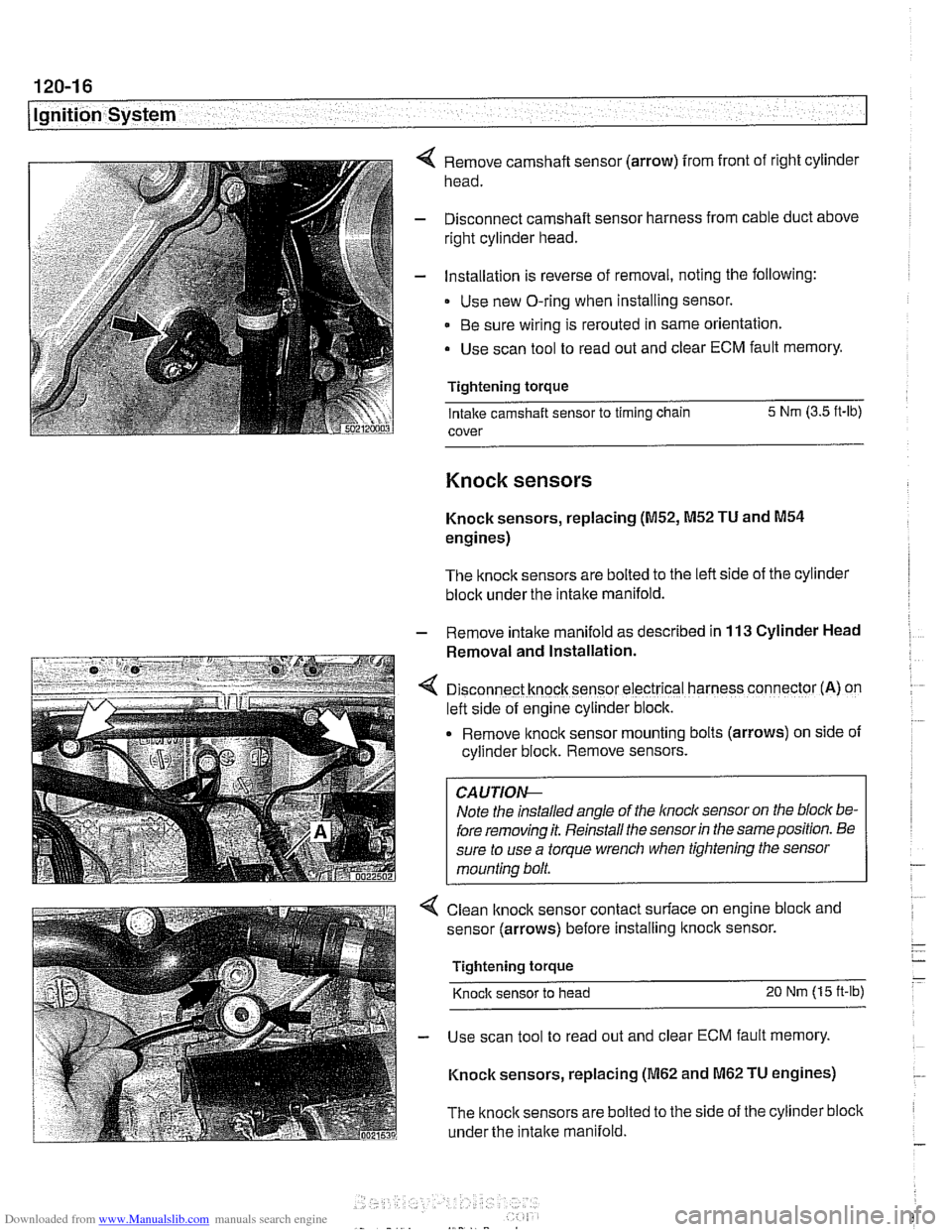
Remove camshaft sensor (arrow) from front of right cylinder
head.
Disconnect camshaft sensor harness from cable duct above
right cylinder head.
Installation is reverse of removal, noting the following:
Use new O-ring when installing sensor.
Be sure wiring is rerouted in same orientation.
Use scan tool to read out and clear ECM fault memory.
Tightening torque Intake camshaft sensor to timing chain 5 Nm
(3.5 ft-lb)
cover
Knock sensors
Knock sensors, replacing (M52, M52 TU and M54
engines)
The knock sensors are bolted to the left side of the cylinder
block under the intake manifold.
- Remove intalte manifold as described in 113 Cylinder Head
Removal and Installation.
D~sconnect knock sensor electrical harness connector (A) on
left side of engine cylinder block.
Remove knock sensor
mount~ng bolts (arrows) on side of
cyllnder block. Remove sensors.
Note the installed angle of the
lnocl~ sensor on the bloc/( be-
fore removing it. Reinstall the sensor
in the same position. Be
sure to use a torque wrench when tightening the sensor
mounting bolt.
< Clean lknock sensor contact surface on engine bloclc and
sensor (arrows) before installing
ltnock sensor.
Tightening torque
Knock sensor to head 20 Nm (15 ft-lb)
- Use scan tool to read out and clear ECM fault memory.
Knock sensors, replacing
(M62 and M62 TU engines)
The
knock sensors are bolted to the side of the cylinder block
under the
intake manifold.
Page 399 of 1002
Downloaded from www.Manualslib.com manuals search engine
Fuel Injection I
Mass air flow (MAF) sensor,
checking and replacing
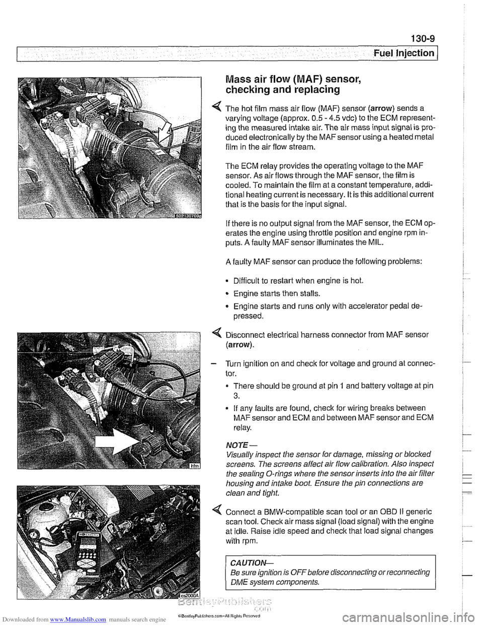
4 The hot film mass air flow (MAF) sensor (arrow) sends a
varying voltage (approx.
0.5 - 4.5 vdc) to the ECM represent-
ing the measured intake air. The air mass input signal is pro-
duced electronically by the
MAFsensorusing a heated metal
film in the air flow stream.
The ECM relay provides the operating voltage to the MAF
sensor. As air flows through the MAF sensor, the film is
-
cooled. To maintain the film at a constant temperature, addi-
tional heating current is necessary. It is this additional current
that is the basis for the input signal.
If there is no output signal from the MAF sensor, the ECM op-
erates the engine using throttle position and engine rpm in-
puts. A faulty MAF sensor illuminates the MIL.
A faulty MAF sensor can produce the following problems:
Difficult to restart when engine is hot.
Engine starts then stalls.
Engine starts and runs only with accelerator pedal de-
pressed.
Disconnect electrical harness connector from MAF sensor
(arrow).
- Turn ignition on and check for voltage and ground at connec-
tor.
There should be ground at pin
1 and battery voltage at pin
3.
If any faults are found, check for wiring breaks between
MAF sensor and ECM and between MAF sensor and ECM
relay.
NOTE-
Visually inspect the sensor for damage, missing or blocked
screens. The screens affect air flow calibration. Also inspect
the sealing O-rings where the sensor inserts into the air
filter
housing and intake boot. Ensure the pin connections are
clean and tight.
4 Connect a BMW-compatible scan tool or an OBD II generic
scan tool. Check air mass signal (load signal) with the engine
at idle. Raise idle speed and check that load signal changes
with rpm.
CA UTIOI\C
Be sure ignition is OFFbefore disconnecting or reconnecting r
1 DME svstem components. 1
Page 405 of 1002
Downloaded from www.Manualslib.com manuals search engine
Fuel injectors, checking and replacing
The fuel injectors are electronically controlled solenoid valves
that provide precisely metered and atomized fuel into the en-
gine intake ports.
The injectors receive voltage from the ECM relay. The ECM
controls the opening by activating the ground circuit
forthe in-
jector valve solenoids. The ECM varies the duration (in milli-
seconds) of "opening" time to regulate the
airlfuel ratio.
For a quick
check of the injectors, run the engine and touch
each injector with a screwdriver or stethoscope. You should
feel a vibration or hear a buzzing
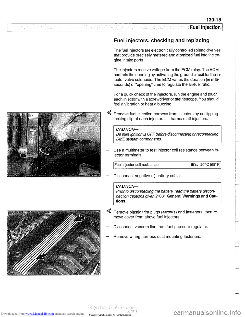
Remove fuel injection harness from injectors by unclipping
locking clip at each injector. Lift harness off injectors.
CA U JIOG
Be sure ignition is OFF before disconnecting or reconnecting
DME system components.
Use a multimeter to test injector coil resistance between in-
jector terminals.
l~uel injector coil resistance 16R at 20" C (68" F)
Disconnect negative
(-) battery cable
CAUTIOG
Prior to disconnecting the battery, read the battery discon-
nection cautionsgiven
in 001 General Warnings and Cau-
tions.
4 Remove plastic trim plugs (arrows) and fasteners, then re.
move cover from above fuel injectors.
- Disconnect vacuum line from fuel pressure regulator.
- Remove wiring harness duct mounting fasteners.
Page 408 of 1002
Downloaded from www.Manualslib.com manuals search engine
130-1 8
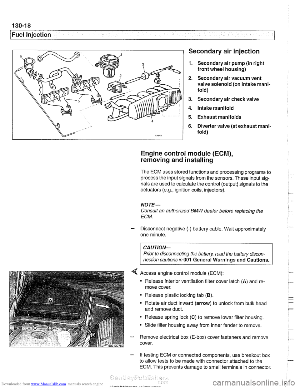
1 Fuel injection Secondary air injection
1. Secondary air pump (in right
front wheel housing)
2. Secondary air vacuum vent
valve solenoid (on intake mani-
fold)
3. Secondary air check valve
4. Intake manifold
5. Exhaust manifolds
6. Diverter valve (at exhaust mani-
fold)
Engine control module (ECM),
removing and installing
The ECM uses stored functions and processing programs to
process the input signals from the sensors. These input sig-
nals are used to calculate the control (output) signals to the
actuators
(e.g., ignition coils, injectors).
NOTE-
Consult an authorized BMW dealer before replacing the
ECM.
- Disconnect negative (-) battery cable. Wait approximately
one minute.
Prior to disconnecting the
battely, read the battery discon-
nection cautions in
001 General Warnings and Cautions.
Access engine control module (ECM):
Release interior ventilation filter cover latch
(A) and re-
move cover.
Release plastic locking tab
(B).
Rotate air duct inward (arrow) to unloclc from bulk head
and remove duct.
Release spring lock
(C) to remove lower filter housing.
Slide filter housing away from inner fender to remove.
- Remove electrical box (E-box) cover fasteners and remove
cover.
- If testing ECM or connected components, use breakout box
to allow tests to be made with connector attached to the
ECM. This prevents damage to small terminals in connector.
Page 430 of 1002
Downloaded from www.Manualslib.com manuals search engine
130-40
Fuel Injection
Engine control module (ECM),
removing and installing
The ECM uses stored functions and processing programs to
process the input signals from the sensors. These input sig-
nals are used to calculate the control (output) signals to the
actuators
(e.g., ignition coils, injectors).
NOTE-
Consult an authorized BMW dealer before replacing the
ECM.
- Disconnect negative (-) battery cable. Wait approximately
one minute.
CAUTION-
Prior to disconnecting the batteg read the battery discon-
nection cautions
in 001 General Warnings and Cautions.
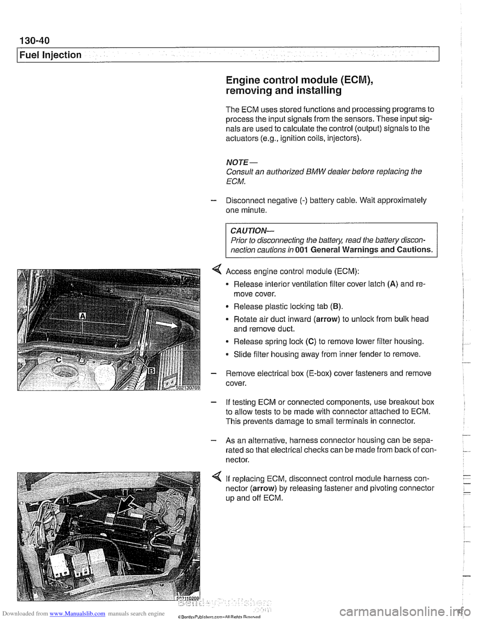
4 Access engine control module (ECM):
Release
interlor ventilation filter cover latch (A) and re-
move cover.
Release plastic loclting tab
(B).
Rotate air duct inward (arrow) to unloclt from bulk head
and remove duct.
Release spring lock
(C) to remove lower filter housing.
Slide
f~lter hous~ng away from inner fender to remove.
- Remove electrical box (E-box) cover fasteners and remove
cover.
- If testing ECM or connected components, use breakout box
to allow tests to be made with connector attached to ECM.
This prevents damage to small terminals in connector.
- - As an alternative, harness connector housing can be sepa-
rated so that electrical checks can be made from
back of con-
nector.
4 If replacing ECM, disconnect control module harness con-
nector (arrow) by releasing fastener and pivoting connector
up and off ECM.
Page 507 of 1002
Downloaded from www.Manualslib.com manuals search engine
170-1 1
Radiator and Cooling system/
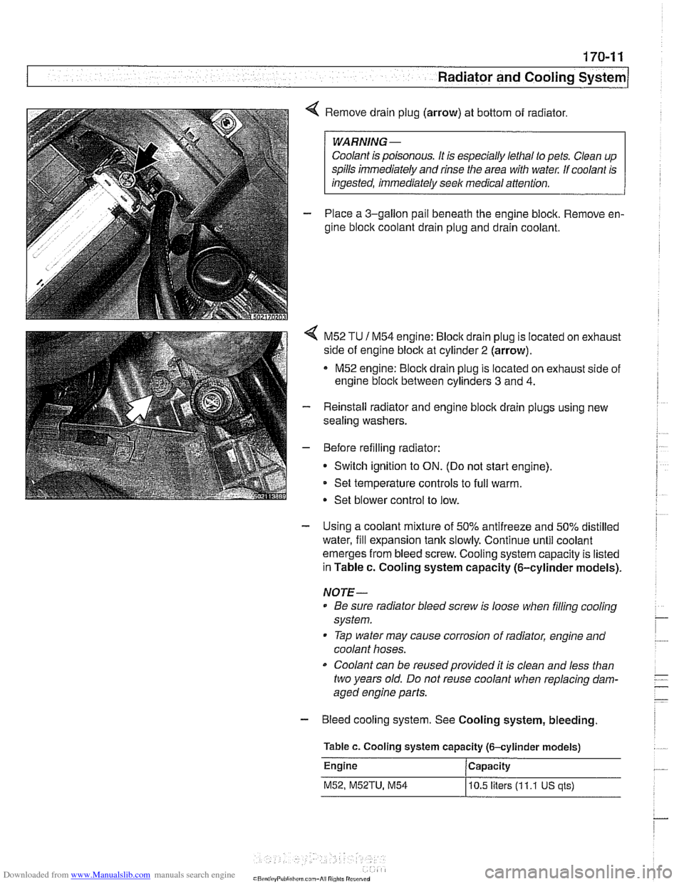
4 Remove drain plug (arrow) at bottom of radiator.
Coolant is poisonous. It is especially lethal to pets. Clean up
spills immediately and rinse the area with
wate,: If coolant is
- Place a 3-gallon pail beneath the engine block. Remove en-
gine block coolant drain plug and drain coolant.
< M52 TU 1 M54 engine: Bloclc drain plug is located on exhaust
side of engine block at cylinder
2 (arrow).
M52 engine:
Bloclc drain plug is located on exhaust side of
engine
bloclc between cylinders 3 and 4.
- Reinstall radiator and engine block drain plugs using new
sealing washers.
- Before refilling radiator:
Switch ignition to
ON. (Do not start engine).
Set temperature controls to full warm.
Set blower control to low.
- Using a coolant mixture of 50% antifreeze and 50% distilled
water, fill expansion tank slowly. Continue until coolant
emerges from bleed screw. Cooling system capacity is listed
in Table c. Cooling system capacity (6-cylinder models).
NOTE-
Be sure radiator bleed screw is loose when filling cooling
system.
Tap water may cause corrosion of radiator, engine and
coolant hoses.
Coolant can be reusedprovided it is clean and less than
two years old. Do not reuse coolant when replacing dam-
aged engine parts.
- Bleed cooling system. See Cooling system, bleeding
Table c. Cooling system capacity (6-cylinder models)
Engine Capacity
M52, M52TU, M54
10.5 liters (1 1.1 US qls)
Page 509 of 1002
Downloaded from www.Manualslib.com manuals search engine
170-1 3
Radiator and Cooling ~vsteml
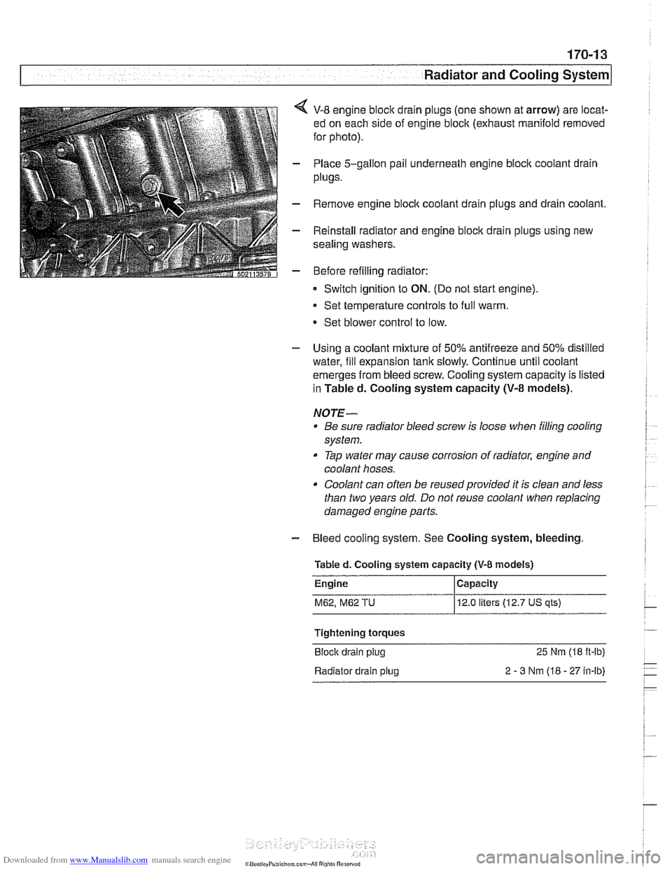
< V-8 engine bloclc drain plugs (one shown at arrow) are locat-
ed on each side of engine block (exhaust manifold removed
for photo).
- Place 5-gallon pail underneath engine block coolant drain
plugs.
- Remove engine bloclc coolant drain plugs and drain coolant.
- Reinstall radiator and engine block drain plugs using new
sealing washers.
- Before refilling radiator:
Switch ignition to
ON. (Do not start engine)
Set temperature controls to full warm.
- Set blower control to low.
- Using a coolant mixture of 50% antifreeze and 50% distilled
water, fill expansion tank slowly. Continue until coolant
emerges from bleed screw. Cooling system capacity is listed
in Tabled. Cooling system capacity
(V-8 models).
NOTE- Be sure radiator bleed screw is loose when filling cooling
system.
Tap water may cause corrosion of radiator, engine and
coolant hoses.
Coolant can often be reused provided it is clean and less
than two years old. Do not reuse coolant when replacing
damaged engine parts.
- Bleed cooling system. See Cooling system, bleeding
Tabled. Cooling system
capacity (V-8 models)
M62, M62 TU 12.0 liters (12.7 US qts)
Tightening torques
Block drain plug
25 Nm (18 ft-lb)
Radiator drain plug
2 - 3 Nm (18 - 27 in-lb)
Page 904 of 1002
Downloaded from www.Manualslib.com manuals search engine
1 Central Locking and Anti-Theft
NOJE-
A single unlock request from the driver's door with the FZV
key unlocks the driver's door only.
A second unlock request
unlocls the remaining doors and trunk. This feature can be
modified for individual users with the Key Memory capabil-
ities to activate all lock actuators simultaneously See Car
Memory
/ Key Memory later in this section.
Starting with 2000 models, the battery in the FZV ignition
Icey is recharged by the ignition switch ring antenna while
the ley is in the ignition switch.
Transmitter self-test (models to
1999)
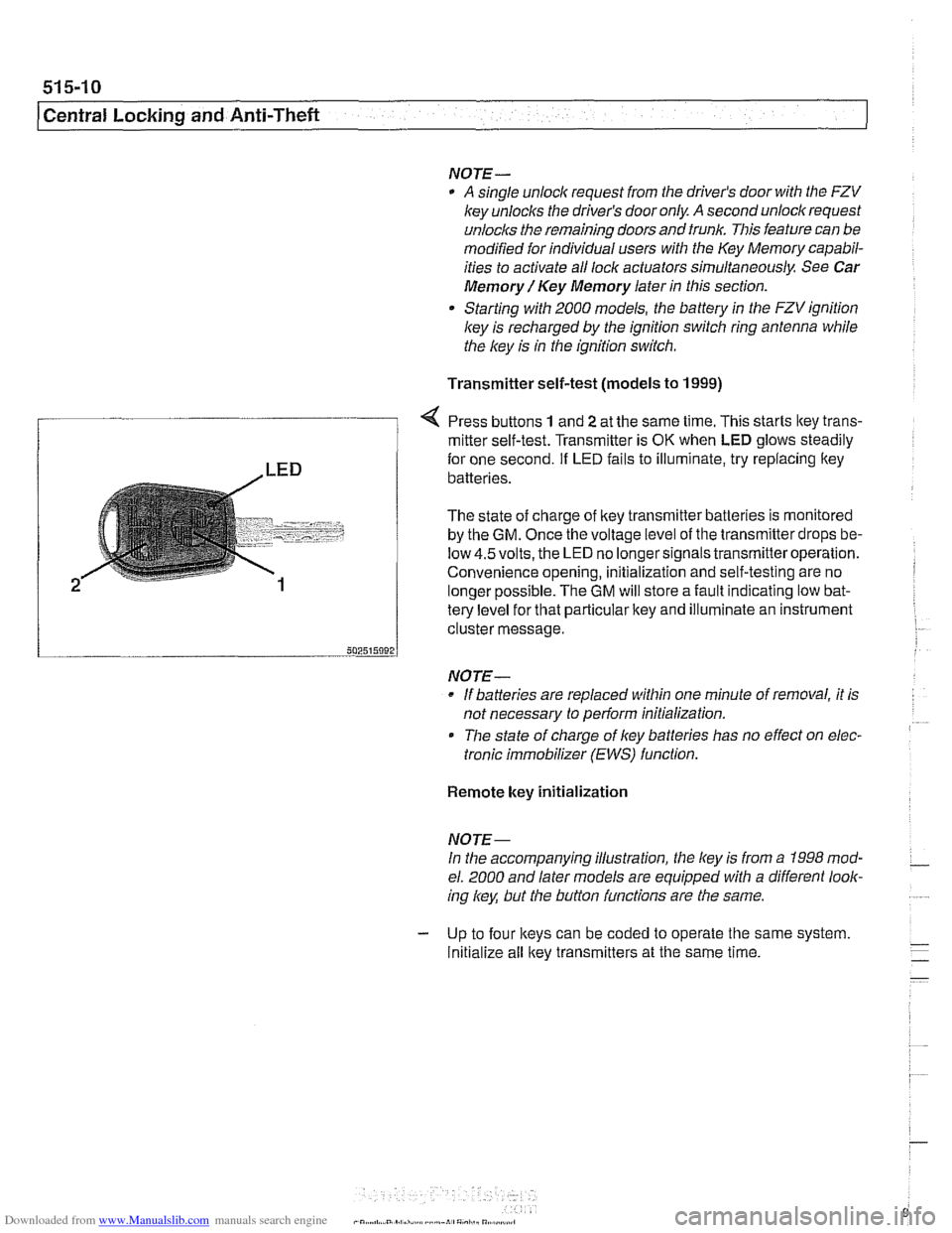
Press buttons 1 and 2 at the same time. This starts ltey trans-
/ mitter self-test. Transmitter is OK when LED glows steadily
te{le"el for that particular key and illuminate an instrument
cluster message.
-- 502515092 J
NO JE-
If batteries are replaced within one minute of removal, it is
not necessary to
periorm initialization.
Tlie state of charge of key batteries has no effect on elec-
tronic immobilizer (EWS) function.
2
Remote key initialization
for one second. If LED fails to illuminate, try replacing ltey~
batteries.
The state of charge of key transmitter batteries is monitored
by the
GM. Once the voltage level of the transmitter drops be-
low
4.5volts, the LED no longersignals transmitteroperation.
Convenience opening, initialization and self-testing are no
lonaer ~ossible. The GM will store a fault indicatina low bat-
NOJE-
In the accompanying illustration, the key is from a 1998 mod-
el. 2000 and later models are equipped with a different look-
ing
/
Initialize all key transmitters at the same time.
Page 917 of 1002
Downloaded from www.Manualslib.com manuals search engine
Central Lockina and ~nti- heft
EWS control module, replacing
NOTE-
EWS control module location varies depending on version of
EWS installed.
Checlc the table €39 EWS applications.
- Disconnect battery negative (-) cable.
CA UTIOI\C
Prior to disconnecting the battery, read the battery discon-
nection cautions given in
001 General Warnings and Cau-
tions.
- EWS II: Control module is accessible from behind glove com-
partment.
Remove trim below glove compartment.
Lower relay and module holder to access EWS control
module
EWS
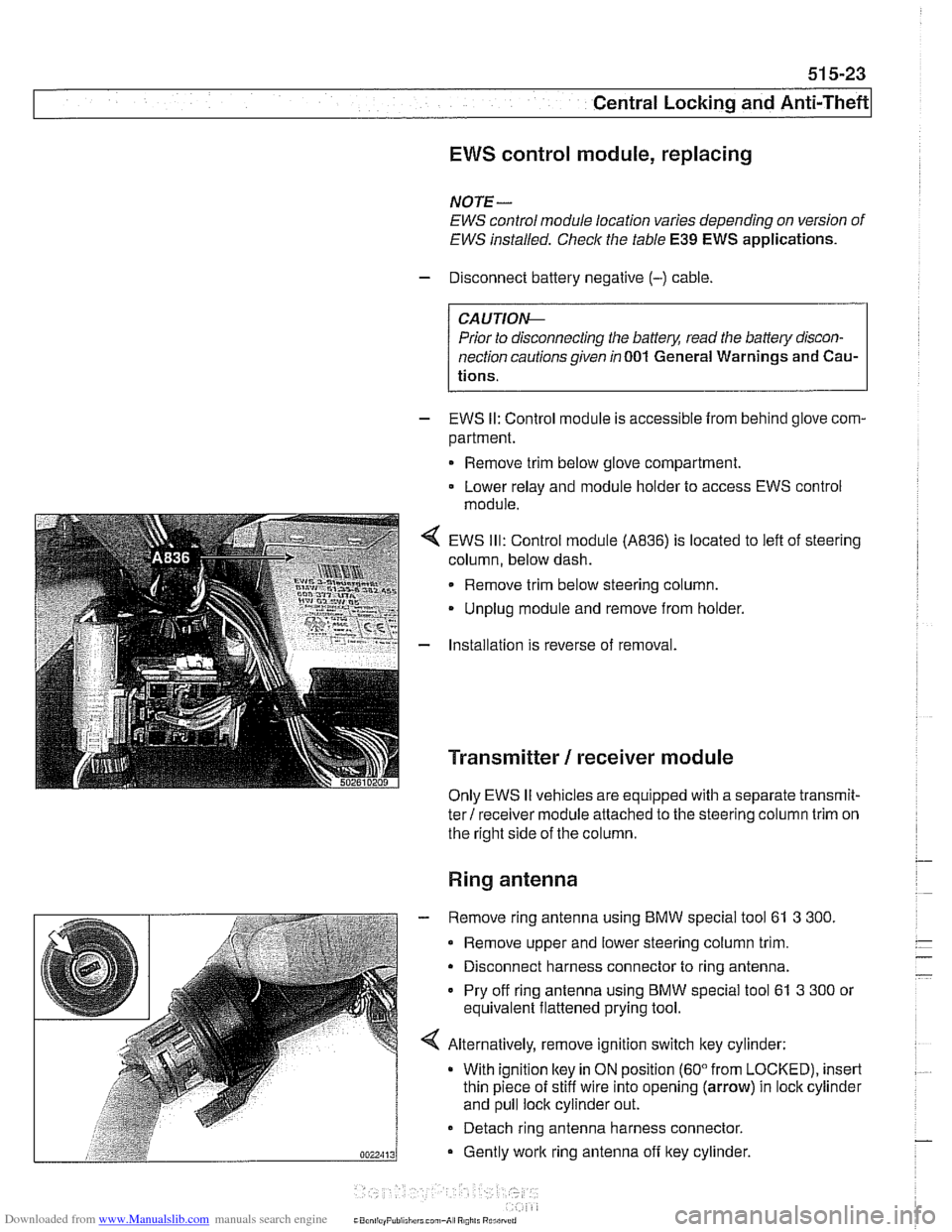
Ill: Control module (A836) is located to left of steering
column, below dash.
Remove trim below steering column.
Unplug module and remove from holder.
Installation is reverse of removal.
Transmitter / receiver module
Only EWS II vehicles are equipped with a separate transmit-
ter! receiver module attached to the steering column trim on
the right side of the column.
Ring antenna
- Remove ring antenna using BMW special tool 61 3 300.
Remove upper and lower steering column trim.
Disconnect harness connector to ring antenna.
Pry off ring antenna using
BMW special tool 61 3 300 or
equivalent flattened prying tool.
Alternatively, remove ignition switch key cylinder: With ignition
ltey in ON position (60" from LOCKED), insert
thin piece of stiff wire into opening (arrow) in lock cylinder
and pull lock cylinder out.
- Detach ring antenna harness connector.
Gently
work ring antenna off ltey cylinder.
CaonliayPuliiliirrl can,-A, R0,il. Rurilrrrri