Maf sensor BMW 540i 1997 E39 User Guide
[x] Cancel search | Manufacturer: BMW, Model Year: 1997, Model line: 540i, Model: BMW 540i 1997 E39Pages: 1002
Page 449 of 1002
Downloaded from www.Manualslib.com manuals search engine
130-59
Fuel Injection
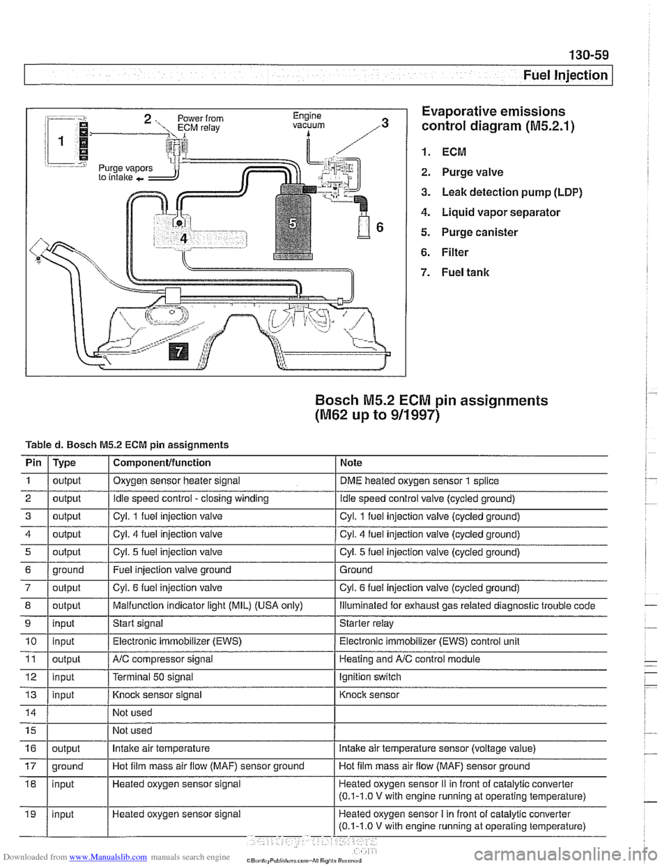
:-- -i. Evaporative emissions
1.
control diagram (M5.2.1)
i 1
i I @ 1. ECM r.=.:-:, 2. Purge valve
3. Leak detection pump (LDP)
4. Liquid vapor separator
5. Purge canister
6. Filter
Bosch M5.2 ECM pin assignments
(M62 up to 911997)
Tabled. Bosch M5.2 ECM pin assignments
I' 1- 1. . . -
4 1 output / Cyl. 4 fuel injection valve I Cyl. 4 fuel injection valve (cycled ground)
Pin
1
2
3
i I
I
7 / output I Cyl. 6 fuel injection valve I Cyl. 6 fuel injection valve (cycled ground)
Type
output
output
output
I I ,
8 1 output I Malfunction indicator light (MIL) (USA only) I lliumlnated for exhaust gas related diagnostic trouble code
5
Component/function
Oxygen sensor heater signal
Idle speed control -closing winding
Cvl. 1 fuel iniection valve Note
DME heated oxygen sensor
1 splice
idle speed control valve (cycled ground)
Cvl. 1 fuel iniection valve lcvcled around)
6 1 ground I Fuel injection valve ground 1 Ground
output
9
Not
used
Not used
11
12
13
Cyl. 5 fuel injection valve
10 1 input I Electronic immobilizer (EWS) / Electronic immobilizer (EWS) control unit
input
Heated oxygen sensor signal Cyl.
5 fuel injection
valve (cycled ground)
output
input
input
16
Start signal Starter relay
NC compressor signal
Terminal
50 signal
Knock sensor signal
17 1 ground I Hot film mass air flow (MAF) sensor ground I Hot film mass air flow (MAF) sensor ground
output Heating and
A/C control module
Ignition switch
Knock sensor
Intake air temperature intake air temperature sensor (voltage value)
Page 459 of 1002
Downloaded from www.Manualslib.com manuals search engine
--
Fuel Injection I
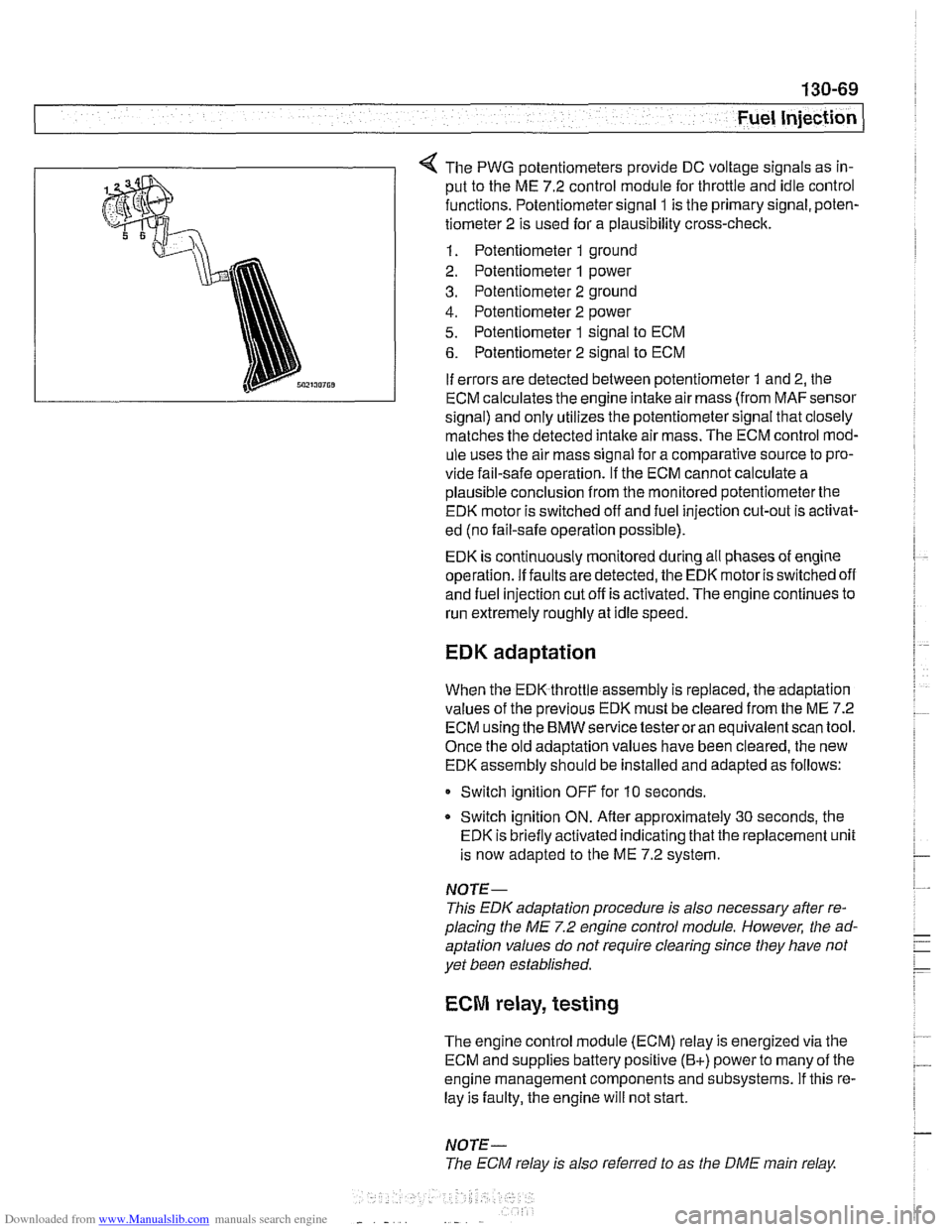
The PWG potentiometers provide DC voltage signals as in-
put to the ME 7.2 control module for throttle and idle control
functions. Potentiometer signal
1 is the primary signal, poten-
tiometer 2 is used for a plausibility cross-check.
1. Potentiometer 1 ground
2. Potentiometer
1 power
3. Potentiometer 2 ground
4. Potentiometer 2 power
5. Potentiometer 1 signal to ECM
6. Potentiometer 2 signal to ECM
If errors are detected between potentiometer
1 and 2, the
ECM calculates the engine intake air mass (from
MAFsensor
signal) and only utilizes the potentiometer signal that closely
matches the detected
intake air mass. The ECM control mod-
ule uses the air mass signal for a comparative source to pro-
vide fail-safe operation.
If the ECM cannot calculate a
plausible conclusion from the monitored potentiometerthe
EDK motor is switched off and fuel injection cut-out is activat-
ed (no fail-safe operation possible).
EDK is continuously monitored during all phases of engine
operation. If faults are detected, the EDK motor is switched off
and fuel injection cut off is activated. The engine continues to
run extremely roughly at idle speed.
EDK adaptation
When the EDK throttle assembly is replaced, the adaptation
values of the previous EDK must be cleared from the ME 7.2
ECM using the BMW service testeroran equivalentscan tool.
Once the old adaptation values have been cleared, the new
EDK assembly should be installed and adapted as follows:
0 Switch ignition OFF for 10 seconds.
* Switch ignition ON. Afler approximately 30 seconds, the
EDK is briefly activated indicating that the replacement unit
is now adapted to the ME 7.2 system.
NOTE-
This EDK adaptation procedure is also necessary after re-
placing the
ME 7.2 engine control module. However, the ad-
aptation values do not require clearing since they have not
yet been established.
ECM relay, testing
The engine control module (ECM) relay is energized via the
ECM and supplies battery positive
(B+) power to many of the
engine management components and subsystems. If this re-
lay is faulty, the engine will not start.
NOTE-
The ECM relay is also referred to as the DME main relay
Page 463 of 1002
Downloaded from www.Manualslib.com manuals search engine
( Mass Air Flow Sensor
1" Intake air temp. (NTC)
Sensor qround
Reference voltage . . . -., f fitr mass signal I
Fuel Injection I
Release fuel injector locking clips (arrow).
- Remove fuel injector loom boxes and lay to one side.
- Remove 4 fuel rail mounting fasteners.
4 Disconnect fuel line at quick-disconnect. To disconnect,
press in plastic collar (arrow) and separate fuel line.
WARNING -
Fuel may be expelled underpressure. Do not srnol(e or work
near heaters or
other fire hazards. Keep a fire extinguisher
handy. Before disconnecting fuel hoses, wrap a cloth around
fuel hose
to absorb anv leakinq fuel. Plug all open fuel lines.
- Lifl fuel rail and injectors straight up to remove.
- lnstallation is reverse of removal. Use new injector seals and
clamps during installation.
Mass air flow (MAF) sensor,
removing and installing
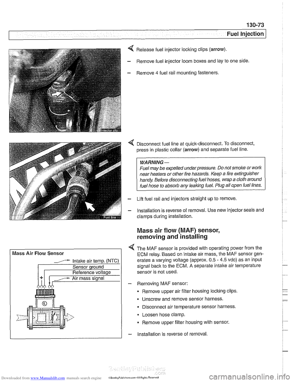
4 The MAF sensor is provided with operating power from the
ECM relay. Based on intake air mass, the MAF sensor gen-
erates a varying voltage (approx. 0.5
- 4.5 vdc) as an input
signal
back to the ECM. A separate intalte air temperature
sensor is not used.
- Removing MAF sensor:
Remove upper air filter housing locking clips
Unscrew and remove sensor harness.
Disconnect air temperature sensor harness.
Loosen hose clamp.
Remove upper filter housing with sensor.
- lnstallation is reverse of removal
Page 514 of 1002
Downloaded from www.Manualslib.com manuals search engine
Tightening torques Block drain plug to block
25 Nm (18 ft-lb)
Radiator drain plug to radiator 2 - 3 Nm (18 - 27 in-lb)
Thermostat housing to
cylinder head 10 Nm (89 in-lb)
Thermostat, removing and installing
(V-8 models)
The electrically-heated thermostat is an integral parl of the
thermostat housing. The operation of the thermostat is moni-
tored by the engine control module (ECM).
- If a faulty thermostat is suspected, use appropriate scan tool
to interrogate ECM for stored fault codes.
- Drain radiator and engine block. See Coolant, draining and
filling
(V-8 models).
WARNING -
Allow cooling system to cool before opening or draining the
system.
- Disconnect mass air flow (MAF) sensor electrical harness
connector. Remove air intake duct together with MAF sensor.
- Remove mechanical cooltng fan and fan shroud. See Me-
chanical (viscous clutch) cooling fan, removing and
in-
stalling.
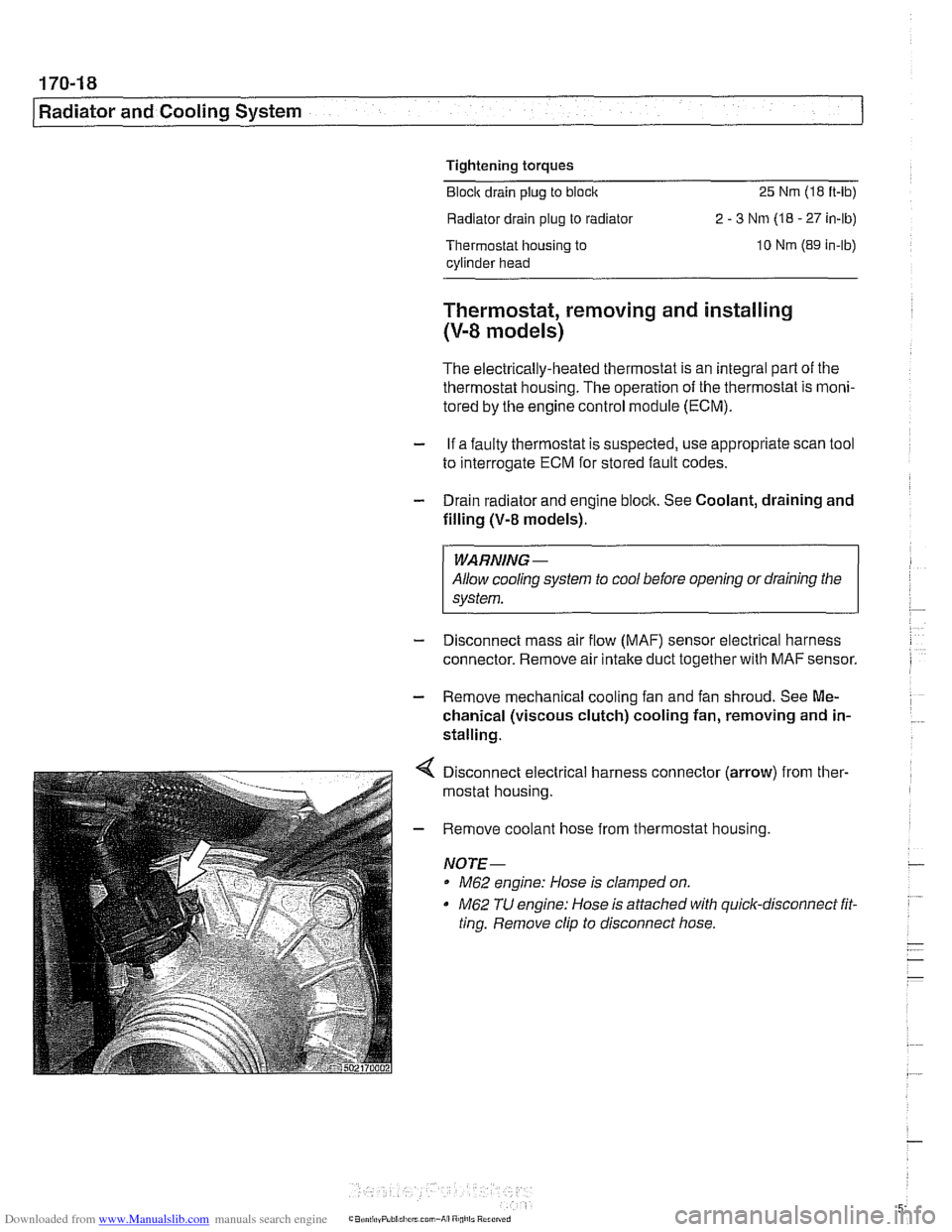
Disconnect electrical harness connector (arrow) from ther-
mostat housing.
Remove coolant hose from thermostat housing.
NOTE-
M62 engine: Hose is clamped on.
M62 TU engine: Hose is attached with quick-disconnect fit.
ting. Remove clip to disconnect hose.
Page 516 of 1002
Downloaded from www.Manualslib.com manuals search engine
.," --
Radiator and Cooling System --- 1
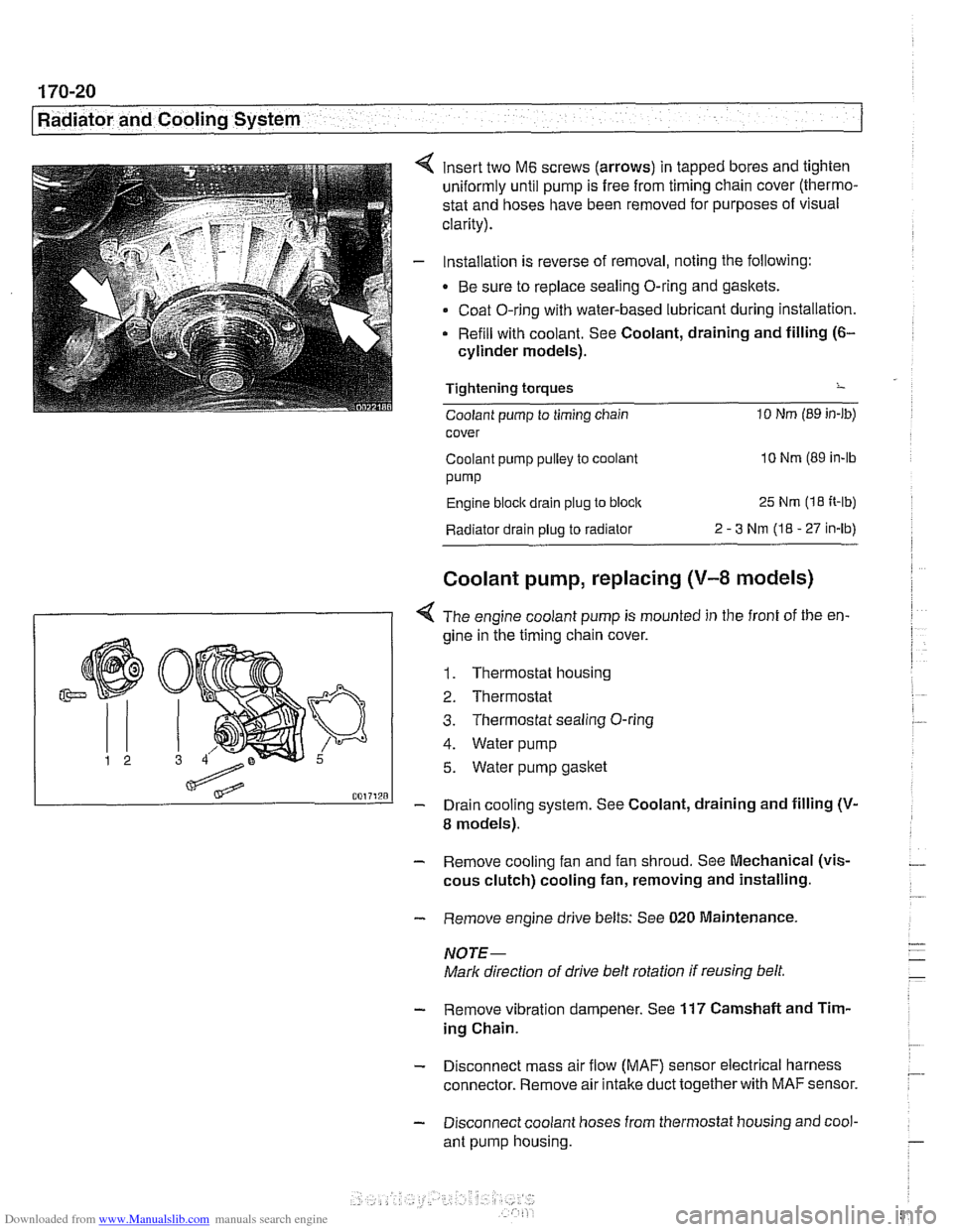
insert two M6 screws (arrows) in tapped bores and tighten
uniformly until pump is free from timing chain cover (thermo-
stat and hoses have been removed for purposes of visual
clarity).
Installation is reverse of removal, noting the following:
Be sure to replace sealing O-ring and gaskets.
Coat O-ring with water-based lubricant during installation.
Refill with coolant. See Coolant, draining and filling
(6-
cylinder models).
Tightening torques
-
Coolant pump to timing chain 10 Nm (89 in-lb)
cover
Coolant pump pulley to coolant
10 Nm (89 in-lb
pump
Engine block drain plug to block 25 Nm (1 8 It-lb)
Radiator drain plug to radiator 2 - 3 Nm (I8 - 27 in-lb)
Coolant pump, replacing (V-8 models)
I 1 < The engine coolant pump is mounted in the front of the en-
gine in ;he timing chain cover.
1. Thermostat housing
2. Thermostat
3. Thermostat sealing O-ring
4. Water pump
5. Water pump gasket
- Drain cooling system. See Coolant, draining and filling (V-
8 models).
- Remove cooling fan and fan shroud. See Mechanical (vis-
cous clutch) cooling fan, removing and installing.
- Remove engine drive belts: See 020 Maintenance.
NOTE-
Mark direction of drive belt rotation if reusing belt,
- Remove vibration dampener. See 117 Camshaft and Tim-
ing Chain.
- Disconnect mass air flow (MAF) sensor electrical harness
connector. Remove air intake duct together with
MAF sensor.
- Disconnect coolant hoses from thermostat housing and cool-
ant pump housing.
Page 518 of 1002
Downloaded from www.Manualslib.com manuals search engine
.. - --
Radiator and Cooling System
Tightening torques
Coolant pump to timing chain 10
Nm (89 in-lb)
cover
Coolant pump
pulley to coolant
pump
10 Nm (89 in-lb
Engine
blocic drain plug to block 25 Nm (18 ft-lb)
Radiator drain plug to radiator
2-3Nm(18-27in-lb)
Thermostat cover to coolant
pump assembly 10 Nm (89 in-lb)
Radiator, removing and installing
Removal of the radiator is similar for V-8 and 6-cylinder mod-
els.
- Raise front of car and support safely.
WARNING -
Make sure the car is stable and well supported at aN times.
Use a professional automotive liff
orjaclc stands designed for
- Remove splash shield from under engine.
- Drain radiator and engine block. See Coolant, draining and
filling
(V-8 models).
WARNING -
Allow cooling system to cool before opening or draining sys-
tem.
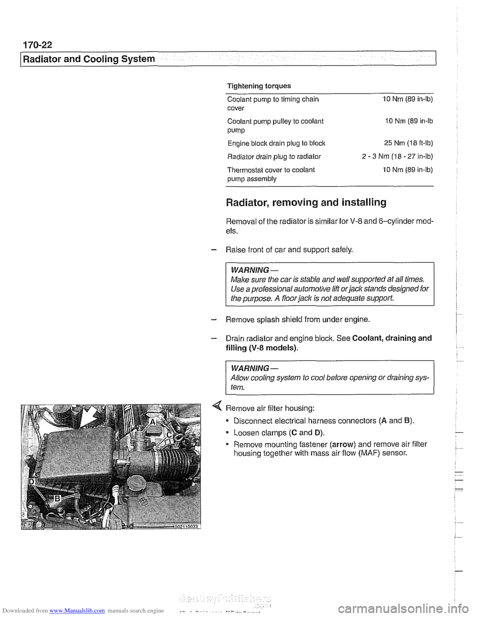
< Remove air filter housing:
Disconnect electrical harness connectors
(A and B).
Loosen clamps (C and D).
Remove mounting fastener (arrow) and remove air filter
housing together with mass air flow
(MAF) sensor.
Page 997 of 1002
Downloaded from www.Manualslib.com manuals search engine
INDEX 7
WARNING
Your common sense, good
judgement, and general alertness are
crucial to safe and successful service
work. Before
attempting any work on
your BMW, be sure to read 001
General Warnings and Cautions
and the copyright page at the front of
the manual. Review these warnings
and cautions each time you prepare
to
work on your BMW. Please also
read any warnings and
caulions that
accompany
/he procedures in the
manual.
Jack stands
010-16
Jump starting 010-19
Keys
515-1 1
Knock sensor
see Ignition system
Leak detection,
fuel tanlr
see Fuel tank, leak detection unit
Leather upholstery
see Maintenance, leather
upholstery and trim
LDP
(leak detection pump)
see Fuel
tanir, leal( detection unit
Level sender
see Fuel tank
see also Fuel pump
License
plate iight
630-1 1
Lifters see Cylinder head and vaivetrain
Lifting the car
010-5 Lights
bulb applications
630-2
control module (LCM) 630-3
foglights 630-8 headiighls 630-4
automatic headlight adjustment
(LWR)
630-7
vertical aim system 630-8 interior lights 630-12
bulb applications 630-13
side turn signal 630-9
taillight 630.10 trunk light bulb 630-14
turn signals, taillights 630-12
LOClCS see Central loci(ing
see also Door loclrs
Lubrication system
oil
level warning switch, replacing
119-20
oil pan, removinglinstalling
6-cylinder 119-10
V-E lower 119-13 V-8 upper 119-15
oil pressure
checiring 11
9-4
warning system, testing 119-5 warning switch, replacing 119-20
oil pressure
reliel valve
6-cylinder 119-26
V-8 11 9-27
oil pump, removinglinstalling
6-cylinder
119-22
V-8 1 19-4
troubieshooting 119-3
Luggage compartment
seeTrunk
MAF (mass air flow) sensor
see 130 under appropriate fuel
injection system Maintenance
accelerator linkage
020-14 air filter 020-14
automatic transmission 020-29
battery 020-22
body lubrication 020-31 body and interior 020-31
braire fluid 020-24
brake padlrotor wear 020-24
brake system 020-25 clutch fluid 020-26
cooling system 020-15
CV ioint boots 020-27
differential oil level 020-26
drive bells 020-16 engine comparlmenl 020-14
engine cooling system 020-16
engine oil 020-1 1 exhaust system 020-27
exterior washing 020-31
fluid and lubricant specifications 020-9
fuel lilter 020-27 fuel lanir and fuel lines 20-28
idle speed 020-19
inspection 020-5
interior care 020-31
lealher upholslery and trim 020-31
maintenance tables 020-6
manual transmission oil 020-30
microiilter 020-22 oxygen sensors 130-72, 180-8
parlcing brake 020-25
power steering fluid level 020-20
seat belts
020-32 service indicator 020-3
spark plugs 020-20
special cleaning 020-32 suspension, front 020-29
suspension, rear 020-29
tires 020-29
washing
020-32
waxing 020-32 windshield wiper blade 020-33
wheels, aligning 020-30
Malfunction indicator iight (MIL)
OED-2
Manifold, exhaust
see Exhaust system
Manifold,
intake
see Intake maniiold
Page 998 of 1002
Downloaded from www.Manualslib.com manuals search engine
Manual transmission
applications 200-2. 230-5
back-up light switch, replacing 230-6
gear ratios 230-6
gearshift
see Gearshiit
ID tag 200-2
fluid 020-1 0. 200-4 fluid service 230-6
oil seals
input shaft seal, replacing
230-17
output shalt seal, replacing 230-1 1
selector
shaft seal, replacing 230-8 pilot bearing 210-16
removallinstallation 230-19
see also Maintenance
Map light
see Lights, interior
Mass air flow
(MAF) sensor
see 130 under appropriate fuel
injection syslem
Master cylinder
see Brakes
see also Clutch, hydraulics
MDK
130-42
Microfilter see
NC, ventilation microfilter
see also Maintenance
Mirror see Exterior trim
Misfire see Ignition syslem, diagnosis
Motor mount
see Engine,
mounl
MRS (multiple restraint system)
see Airbag system (SRS)
Muffler
see Exhaust syslem
Neutral safety switch
see Automatic transmission, range
switch
OED II (on-board diagnostics)
OED-l
Oil change equipment 010-16
Oil level sensor
see Lubrication system
Oil pan
see Lubrication system
OH pressure
see Lubrication system
Oil pump
see Lubrication system
Oil service 020-1 1
On-Board Monitor
640-12
On-board diagnostics OED-1
Outside air temperature sensor
610-14
Outside door handle
see Door
loclc
Outside mirror switch
see Switches
Output
shaft oil seal
see Manual transmission, oil seals
Overheating
see Cooling system, troubleshooting
Overload protection
600-11
Oxygen sensors
130-72, 180-8
P codes OED-10
Panic mode operation
515-11
Parking brake
see Brakes
see also Maintenance
Parts, buying
010-11
Pedal cluster switches
see Switches
Pedal position sensor (PWG)
6-cvlinder
enqine
V-8 engine (M62 TU) 130-68
Pitman arm
see Steering
Power steering
see Steering
Power steering
fluid
see Maintenance
Power window switch
512-3 see also Switches
PWG see Pedal position sensor
(PWG)
Racic and pinion steering
see Steering
Radiator see Cooling system
Radiator cooling fan seeCooling system, cooling fan
see also Cooling system, electric fan
Radiator grill
see Exterior
trim
Radio
650-2 see also Antenna
see also Speakers
Rain sensor
611-6
Raising car safely
010-5
Readiness codes
OED-6
Rear door window
see Door window
Rear main seal
see Crankshalt oil seals
Rear parcel
sheif
513-16