checking oil BMW 540i 1997 E39 Owner's Manual
[x] Cancel search | Manufacturer: BMW, Model Year: 1997, Model line: 540i, Model: BMW 540i 1997 E39Pages: 1002
Page 405 of 1002
Downloaded from www.Manualslib.com manuals search engine
Fuel injectors, checking and replacing
The fuel injectors are electronically controlled solenoid valves
that provide precisely metered and atomized fuel into the en-
gine intake ports.
The injectors receive voltage from the ECM relay. The ECM
controls the opening by activating the ground circuit
forthe in-
jector valve solenoids. The ECM varies the duration (in milli-
seconds) of "opening" time to regulate the
airlfuel ratio.
For a quick
check of the injectors, run the engine and touch
each injector with a screwdriver or stethoscope. You should
feel a vibration or hear a buzzing
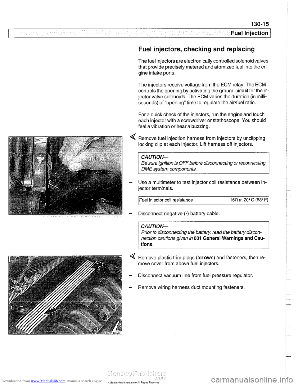
Remove fuel injection harness from injectors by unclipping
locking clip at each injector. Lift harness off injectors.
CA U JIOG
Be sure ignition is OFF before disconnecting or reconnecting
DME system components.
Use a multimeter to test injector coil resistance between in-
jector terminals.
l~uel injector coil resistance 16R at 20" C (68" F)
Disconnect negative
(-) battery cable
CAUTIOG
Prior to disconnecting the battery, read the battery discon-
nection cautionsgiven
in 001 General Warnings and Cau-
tions.
4 Remove plastic trim plugs (arrows) and fasteners, then re.
move cover from above fuel injectors.
- Disconnect vacuum line from fuel pressure regulator.
- Remove wiring harness duct mounting fasteners.
Page 428 of 1002
Downloaded from www.Manualslib.com manuals search engine
130-38
Fuel Injection
Throttle cable, adjusting
(MS 42.0)
The throttle assembly on MS 42.0 cars uses a throttle cable.
The cable should be adjusted any time it is disconnected or
replaced. This procedure requires the factory scan tool or an
equivalent to read and adjust throttle angle. It is recommend-
ed the procedure be done by an authorized
BMW dealer ser-
vice department
Basic adjustment:
Ensure that at idle (accelerator pedal in rest position) throt-
tle cable has detectable play at throttle lever attaching
point. Play must not exceed maximum allowable.
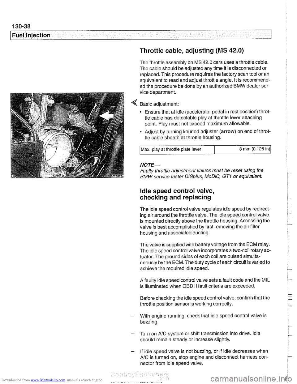
Adjust by turning knurled adjuster
(arrow) on end of throt-
tle cable sheath at throttle housing.
NOTE-
Faulty throttle adjustment values must be reset using the
BMW service tester
DISplus, MoDiC, GTI or equivalent.
Max.
play at throttle plate lever
ldle speed control valve,
checking and replacing
3 mm (0.125 in)
The Idle speed control valve regulates Idle speed by red~rect-
ing air around the throttle valve. The ldle speed control valve
is mounted
d~rectly above the throttle housing. Accessing the
valve is best accomplished by
flrst removing the air fllter
housing and associated ducting.
Thevalve is supplied with batteryvoltage from the ECM relay.
The idle speed control valve incorporates a two-coil rotary ac-
tuator. The ground sides of each coil are pulsed simulta-
neously by the ECM. The duty cycle of each circuit is varied to
achieve the required idle speed.
A faulty idle speed control valve sets a fault code and the MIL
is illuminated when
OED II fault criteria are exceeded.
Before checking the idle speed control valve, confirm that the
throttle position sensor is working correctly.
- With engine running, check that idle speed control valve is
buzzing.
- Turn on AIC system or shift transmission into drive. ldle
should remain steady or increase slightly.
- If idle speed valve is not buzzing, or if idle decreases when
AIC is turned on, stop engine and disconnect harness con-
nector from idle speed valve.
Page 442 of 1002
Downloaded from www.Manualslib.com manuals search engine
.. .-
/Fuel lnjeciion
NOJE-
With engine oft disconnect harness connector and checlc
heating element resistance between white wires on the sen-
sor side of harness. If the element is electrically open (no
continuity), replace sensor.
- If oxygen sensor does not produce a fluctuating voltage and
preheater circuit is
OK, replace sensor.
NOJE-
If not already applied, coat oxygen sensor threads w~th anti-
seize compound before installat~on. Do not get the com-
pound on the sensor tip.
Tightening torque Oxygen sensor to exhaust system
55 Nm (41 ft-lb)
Fuel injectors, checking and replacing
The fuel iniectors are switched on and off (oaened and
closed)
by'the ECM. The injectors are connkcted to acom-
mon power source. A ground signal from the ECM is used to
open and close the injectors.
CA U JIOG
Use only a digital multimeter or an LED injector tester when
testing injectors or wiring. Use of an analog
VOM or incan-
descent test light may damaqe the engine controlmodule.
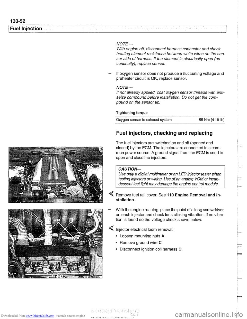
4 Remove fuel rail cover. See 110 Engine Removal and in-
stallation.
With the engine running, place the point of a long screwdriver
on each injector and check for a cliclting vibration.
If no vibra-
tion is found do the voltage
checit shown below.
Injector electrical loom removal:
- Loosen mounting nuts A.
Remove ground wire C.
Disconnect ignition coil harness D
Page 444 of 1002
Downloaded from www.Manualslib.com manuals search engine
130-54
I Fuel Injection ldle speed control valve,
testing and replacing
ldle speed is maintained by the ECM through the idle speed
control valve. The idle control function compensates for en-
gine load and engine operating conditions. ldle speed is
adaptive through the ECM and no adjustments can be made.
Before checking valve, confirm that throttle position sensor is
working correctly.
NOTE-
The test given below is an electrical check only. It does not
check the mechanical operation of the valve. If the valve is
sticking, hanging up or is sluggish in operation, substituting a
Inown good valve is the best way to check it.
With engine running, check that idle speed control valve is
buzzing.
Turn on
AIC or shift car into drive. ldle should remain steady
or increase slightly.
If valve is not buzzing, or if idle decreases in step above, stop
engine and disconnect harness connector from valve.
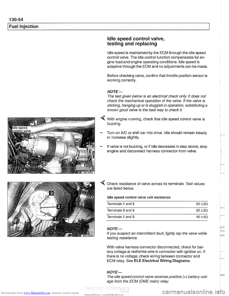
4 Check resistance of valve across its terminals. Test values
are listed below.
ldle speed control valve coil resistance
Terminals
1 and 2 20 +2%
Terminals 2 and 3 20 +2Q
Terminals 1 and 3 40 +4%
NOTE-
If you suspect an intermittent fault, lightly tap the valve while
testing resistance.
With valve harness connector disconnected, check for bat-
tery voltage at redlwhite wire in connector with ignition on.
If . ~~ ~~
there is no voltage, check wiring between connector and 7 ECM relay. See ELE Electrical Wiring Diagrams.
NOTE- - The idle speed control valve receivespositive (+) battery volt-
age from the ECM (DME main) relay
Page 476 of 1002
Downloaded from www.Manualslib.com manuals search engine
.-- -
/ Fuel Tank and Fuel Pump - .. -. -- 1
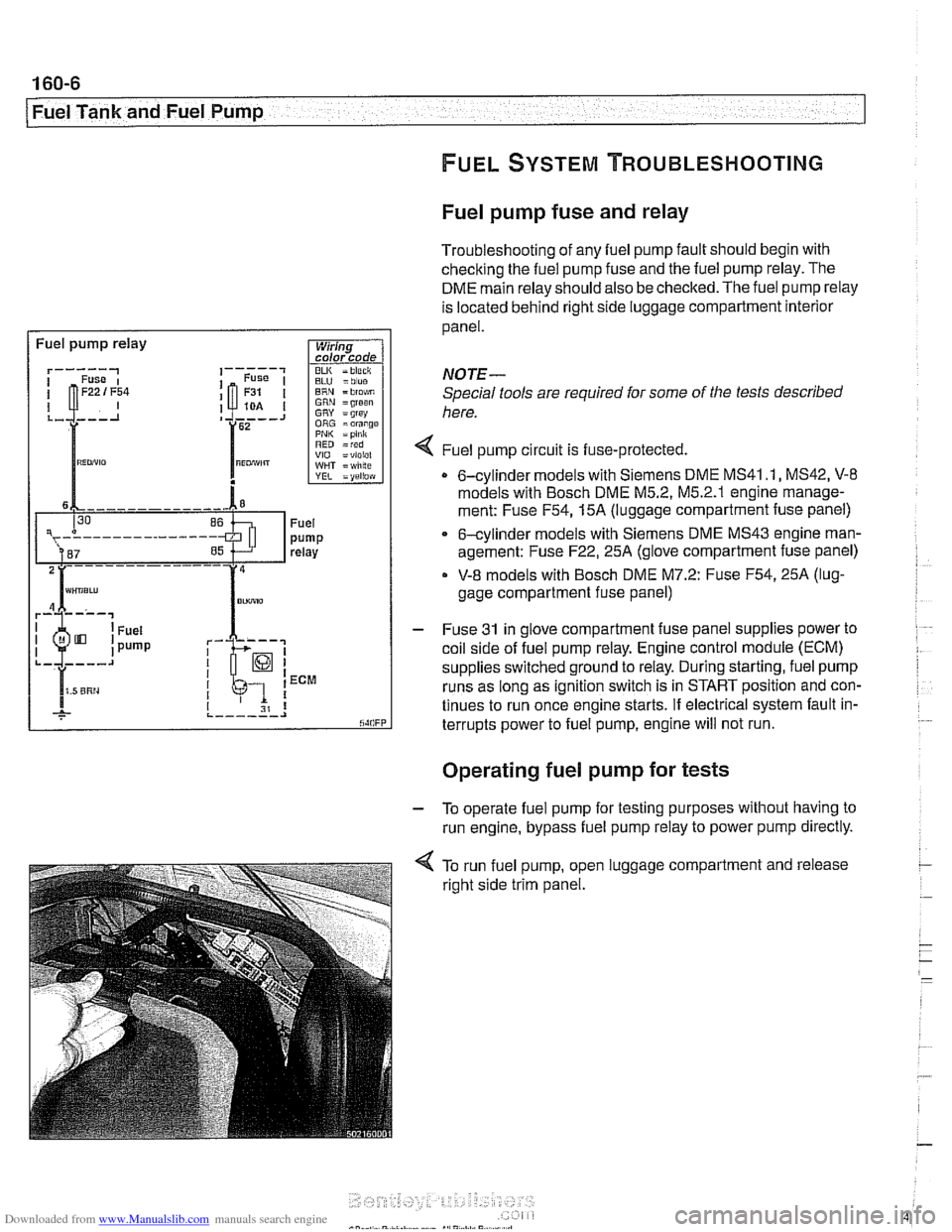
Fuel pump fuse and relay
Troubleshooting of any fuel pump fault should begin with
checking the fuel pump fuse and the fuel pump relay. The
DME main relay should also be checked. The fuel pump relay
is located behind right side luggage compartment interior
panel.
I Fuel pump relay
BLU =blue ERN = blo$,m GRN =groan GRY = grsy ORG =orange PNI< =pink RED =red VIO =violel WHT = wlilte
rk-; I I 1 ECM
I I I 31 8 ,._--___.I
NOTE-
Special tools are required for some of the tests described
here.
4 Fuel pump circu~t is fuse-protected.
0 6-cylinder models with Siemens DME MS41 .I, MS42, V-8
models with Bosch DME M5.2, M5.2.1 englne manage-
ment: Fuse
F54,15A (luggage compartment fuse panel)
6-cylinder models with Siemens DME MS43 engine man-
agement: Fuse
F22,25A (glove compartment fuse panel)
V-8 models with Bosch DME M7.2: Fuse F54,25A (lug-
gage compartment fuse panel)
- Fuse 31 in glove compartment fuse panel supplies power to
coil side of fuel pump relay. Engine control module (ECM)
supplies switched ground to relay. During starting, fuel pump
runs as long as ignition switch is in START position and con-
tinues to run once engine starts. If electrical system fault in-
terrupts power to fuel pump, engine will not run.
. .
Operating fuel pump for tests
- To operate fuel pump for testing purposes without having to
run engine, bypass fuel pump relay to power pump directly.
< To run fuel pump, open luggage compartment and release
right side trim panel.
Page 570 of 1002
Downloaded from www.Manualslib.com manuals search engine
230-6
Manual Transmission
Manual transmissions installed in the 5 Series are normally
filled with a "Lifetime" manual transmission fluid
(BMW MTF
LT-I) and do not require periodic fluid changes. Transmis-
sions filled with MTF LT-I lifetime oil are identified with a yel-
low label near the transmission fill plug labeled "Lifetime Oil
MTF-LT-1".
Transmission fluid level, checking
- Drive vehicle for a few miles to warm transmission.
- Raise and safely support vehicle to access transmission
filler plug.
CAUTION-
Make sure the car is stable and well supporfedat all times.
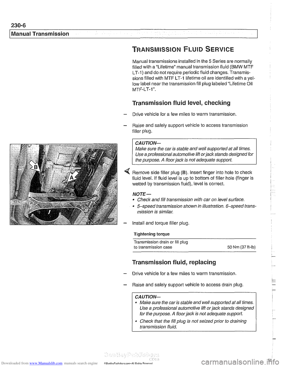
4 Remove side filler plug (B). Insert finger into hole to check
fluid level. If fluid level is up to bottom of filler hole (finger is
wetted by transmission fluid), level is correct.
NOTE-
* Check and fill transmission with car on level surface.
5-speed transmission shown in illustration. 6-speed trans-
mission is similar.
- Install and torque filler plug.
Tightening torque
Transmission drain or fill
plug
to transmission case SO Nm (37 it-lb)
Transmission fluid, replacing
- Drive vehicle for a few miles to warm transmission.
- Raise and safely support vehicle to access drain plug.
CAUTION-
Make sure the car is stable and well supported at all times.
Use a professional automotive lift
orjack stands designed
for the purpose.
A floor jack is not adequate support.
Check that the
fill plug is not seizedprior to draining
transmission fluid.
Page 590 of 1002
Downloaded from www.Manualslib.com manuals search engine
240-6
I Automatic Transmission Automatic transmission fluid (ATF)
The E39 automatic transmission is filled with either Dexron Ill
ATF or Texaco 80728, a life time oil.
CA UTIOI\C
Use only the transmission fluid that is approved for use by
BMW All other fluids will cause non warrantable transmis-
I sion damage.
Mixing different types of transmission fluids will lead to
transmission failure.
NOTE-
The type of transmission lubricant used can be found on a
stickeron the transmission pan. Dexron
111ATF (blacksticker)
reads "ATF-Oil': Special life time oil (green sticker) reads
'Life-Time Oil': If in doubt, consult an authorized
BMW dealer
for alternate fluid use and current information regarding
transmission operating fluids.
ATF level, checking
Check ATF level if there is evidence of a leak, a complaint re-
lated to fluid level or afler transmission repairs.
The automatic transmission is not equipped with a dipstick.
Checking the ATF level requires that the transmission be at
operating temperature during the checking procedure.
NOTE-
Vehicle must be level throughout tests
- Drive vehicle to warm up ATF to operating temperature.
- Connect BMW diagnostic scan tool DiSplus, MoDiC, GTI or
equivalent to determine transmission oil temperature.
ATF level checking
Fluid temperature
30' - 50°C (85' - 120" F)
- With engine running, switch on air conditioning to increase
engine idle speed.
- Apply parking brake.
- While applying foot brake firmly move gear shift selector
lever through
all gear positions, pausing in each gear briefly.
Page 745 of 1002
Downloaded from www.Manualslib.com manuals search engine
33UFinal Drive
General ........................... ,331 -2 Drive Axles ....................... 331 -1 4
Special tools
........................ ,331 -2 Drive axle assembly ................. 331-14
Aluminum suspension components
...... ,331-4 Drive axle, removing and
installing (sedan)
.................... 331-14 ........................ Final Drive ,331 -5
Drive axle, removing
........... ...... Final drive, removing and installing ,331-5 and (Sport Wagon) 331-15
...................... Differential oil level, checking ........... ,331-6 CV joint boots 331-17 Final drive in~ut shaft seal, replacing ..... ,331-7 .
Final drive oitput shaft seals, replacing . . ,331-10
Final drive cover, removing and installing ,331-12
Final drive mounts, replacing .......... ,331-12
Page 750 of 1002
Downloaded from www.Manualslib.com manuals search engine
Final Drive
Tightening torques
F~nal drive to rear axle carrier 105 Nm (77 it-lb)
Driveshaft CV joint to final drive flange
- MlO (Torx bolt) 70
Nm (51 ft-lb)
- M8 (compression nut) 32 Nm (24
ft-lb)
Drive axle to final drive
ilange
Torx bolts (M10) 83 Nm (61 ft-lb)
Torx bolt with
rlbbed teeth (M10) 64 Nm (47 ft-lb)
Torx bolt
wlth ribbed teeth (MI0 sliver) 80 Nm (59 ft-lb)
Torx
bolt with ribbed teeth (M10 black) 100 Nm (74 ft-lb)
* Torx bolt with ribbed teeth (M12) 135 Nm (100 ft-lb)
Differential oil level, checking
The E39 differential is filled with lifetime oil that ordinarily
does not need to be changed. BMW recommends using only
a specially formulated synthetic gear oil
(SAF-XO) that is
available through an authorized BMW dealer parts depart-
ment. For additional information on this lubricant and any oth-
er lubricants that may be compatible, contact an authorized
BMW dealer service department.
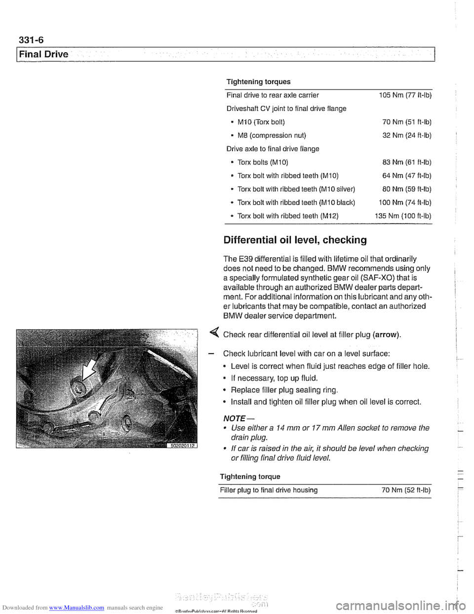
< Check rear differential oil level at filler plug (arrow).
- Check lubricant level with car on a level surface:
Level is correct when fluid just reaches edge of filler hole.
If necessary, top up fluid.
* Replace filler plug sealing ring.
Install and tighten oil filler plug when oil level is correct.
NOTE-
Use either a 14 mm or 17 mm Allen socket to remove the
drain plug.
If car is raised in the air. it should be level when
checkino " or filling final drive fluid level.
- Tightening torque -
Filler plug to final drive housing 70 Nm (52
ft-lb) -
Page 753 of 1002
Downloaded from www.Manualslib.com manuals search engine
331-9
Final Drive
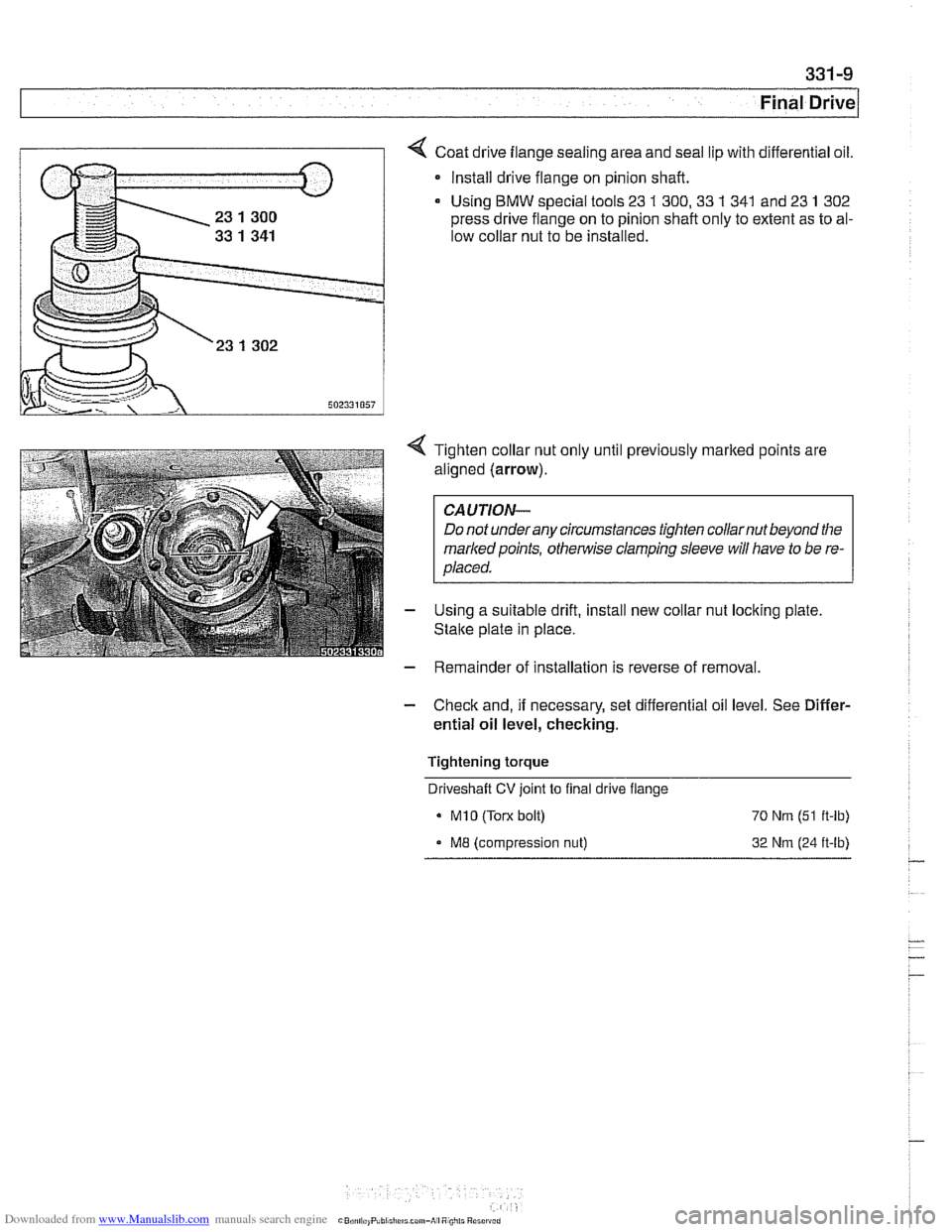
Coat drive flange sealing area and seal lip with differential oil.
* Install drive flange on pinion shaft.
Using
BMW special tools 23 1 300,33 1 341 and 23 1 302
press drive flange on to pinion shaft only to extent as to al-
low collar nut to be installed.
4 Tighten collar nut only until previously marked points are
aligned (arrow).
CAUTION-
Do not underany circumstances tighten collarnut beyond the
markedpoints,
othe~lise clamping sleeve will have to be re-
placed.
- Using a suitable drift, install new collar nut locking plate
Stalte plate in place.
- Remainder of installation is reverse of removal.
- Check and, if necessary, set differential oil level. See Differ-
ential oil level, checking.
Tightening torque Driveshaft
CV joint to final drive flange
MI0 (Torx bolt) 70 Nrn (51 ft-lb)
ME (compression nut) 32 Nrn (24 ft-lb)