CARRIER BMW 540i 1997 E39 Repair Manual
[x] Cancel search | Manufacturer: BMW, Model Year: 1997, Model line: 540i, Model: BMW 540i 1997 E39Pages: 1002
Page 775 of 1002
Downloaded from www.Manualslib.com manuals search engine
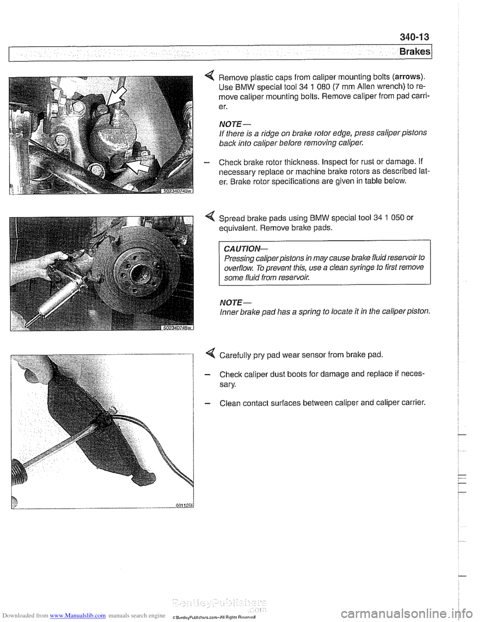
4 Remove plastic caps from caliper mounting bolts (arrows).
Use BMW special tool 34 1 080 (7 mm Alien wrench) to re-
move caliper mounting bolts. Remove caliper from pad
carri-
e r.
NOTE-
If there is a ridge on brake rotor edge, press caliper pistons
back into caliper before removing caliper.
- Check brake rotor thickness. Inspect for rust or damage. if
necessary replace or machine brake rotors as described lat-
er. Bralte rotor specifications are given in table below.
Spread bralte pads using BMW special tool
34 1 050 or
equivalent. Remove brake pads.
CA UTIOG
Pressing caliperpistons in may cause brake fluid reservoir to
overflow. To prevent this, use a clean syringe to first remove
some fluid from reservoir.
NOTE-
Inner brake pad lias a spring to locate it in the caliper piston.
4 Carefully pry pad wear sensor from brake pad
- Check caliper dust boots for damage and replace if neces-
sary.
- Clean contact surfaces between caliper and caliper carrier.
C"..., I,.. P,hi..,,,.r.. mm-*ii Ai"i,li "1.i"~"d
Page 776 of 1002
Downloaded from www.Manualslib.com manuals search engine
340-1 4
Brakes
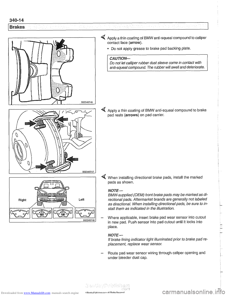
4 Apply a thin coating of BMW anti-squeal compound to caliper
contact face
(arrow).
Do not apply grease to brake pad backing plate.
Right Left
CAUTION-
Do not let calliper rubber dust sleeve come in contact with
anti-squeal compound. The rubber will swell and deteriorate.
4 Apply a thin coating of BMW anti-squeal compound to bralte
pad rests (arrows) on pad carrier.
4 When installing directional brake pads, install the marked
pads as shown.
NOTE-
BMW-supplied (OEM) front brake pads may be marked as di-
rectionalpads. Aftermarket brands are generally not labeled
as directional. When installing directional pads, be sure to in-
stall them as indicated in the illustration.
- Where applicable, insert brake pad wear sensor into cutout
in new pad. Push sensor into pad cutout until it locks into
place.
- -
- NOTE-
If brake lining indicator light illuminatedprior to brake pad re-
placement, replace wear sensor.
- Route pad wear sensor wiring through caliper opening and
under bleeder dust cap.
Page 777 of 1002
Downloaded from www.Manualslib.com manuals search engine
340-1 5
Brakes
- Remainder of installation is reverse of removal.
- Clean brake caliper mounting bolts (7 mm Allen). Replace
ones which are not in perfect condition. Do not grease.
Top up brake fluid to MAX marking.
- Before driving car, pump bralte pedal several times so that
brake pads contact brake rotors.
Check that brake fluid level is correct. Top up if necessary.
Hold ignition key for at least
30 seconds in accessory po-
sition without starting engine. This clears any fault codes in
memory and turns off brake pad warning light.
Tightening torques Brake caliper to pad carrier
(7 mm Allen)
Front caliper
30 Nm (22 It-lb)
- Rear caliper 28 Nm (21 It-lb)
Road wheel to hub
120i 10 Nm (89i7 ft-lb)
Brake rotors, removing and installing
- Raise car and remove wheels
WARNING-
Male sure that the car is firmly supported on jack stands de-
signed for the purpose. Place jack stands beneath structural
chassis points. Do not place jack stands under suspension
parts.
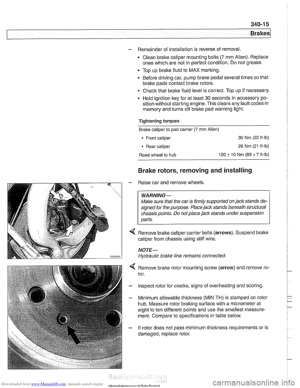
Remove brake caliper carrier bolts (arrows). Suspend brake
caliper from chassis using stiff wire.
NOTE-
Hydraulic brake line remains connected.
4 Remove bralte rotor mounting screw (arrow) and remove ro-
tor.
- Inspect rotor for cracks, signs of overheating and scoring.
- Minimum allowable thickness (MIN TH) is stamped on rotor
hub. Measure rotor braking surface with a micrometer at
eight to ten different points and use the smallest measure-
ment. Compare to specifications in table below.
- If rotor does not pass minimum thickness requirements or is
damaged, replace rotor.
Page 778 of 1002
Downloaded from www.Manualslib.com manuals search engine
1 Brakes
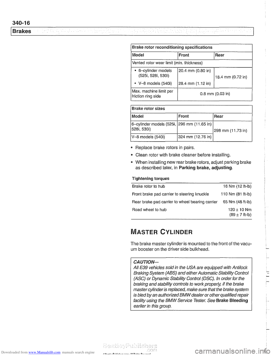
Max. machine limit per
friction ring side 0.8 mm (0.03
in) I
Brake rotor reconditioning specifications
Model
Replace
braite rotors in pairs
Bralre rotor sizes
Clean rotor with brake cleaner before installing.
Front
Model
6-cylinder
models (5251,
5281, 530i)
V-8 models (540i)
* When installing new rear brake rotors, adjust pariting brake
as described later, in Parking brake, adjusting. Rear
Vented rotor wear limit (min. thickness)
Tightening torques
Braite rotor to hub 16 Nm (12 ft-lb)
6-cylinder models
(525i, 5281, 530i)
- V-8 models (540i)
Front
296 mm (1 1.65 in)
324 mm (12.76 in)
Front bralte pad
carrler to steering ltnucitle 110 Nm (81 ft-lb)
Rear
298 mm (1 1.73 in)
Rear
brake pad carrier to wheel bearing carrier 65 Nm (48 ft-lb)
20.4
mm (0.80 in)
28.4 mm (1.12 in)
Road wheel to hub
120ilONm
(89 -t 7 it-lb)
18.4 mm (0.72 in)
The brake master cylinder is mounted to the front of the vacu-
um booster on the driverside bullthead.
-
CAUTION-
All E39 vehicles soldin the USA are equipped with Antilock
Braling System (ABS) and either Automatic Stability Control
(ASC) or Dynamic Stability Control (DSC).
In order for the
braling and stability controls to work properk if the brake
master cylinder is replaced, make sure that the brake system
is bled
by an authorized BMW dealer or other qualified repair
facility
using the BMW Service Tester. See Brake Bleeding
earlier
in this group.
Page 788 of 1002
Downloaded from www.Manualslib.com manuals search engine
1 Brakes
ABS COMPONENT REPLACEMENT
CA UTIOW-
If the tires on the car are of different makes, the ABS/trac-
tion controlsystem may overreact. Only fit tires of the same
make and treadpattern.
In adverse conditions, such as trying to rock the car out
of deep snow or other soft surface, or when snow
chains are fitted, it is advisable to switch off traction
control and allow
tlie car driveline to operate conven-
tionally.
All E39 vehicles are equipped with
Antilock Braking System
(ABS). Early production models featured ABS with Automatic
Stability Control (ABS
I ASC). Later models came equipped
with ABS and Dynamic Stability Control (ABS
/ DSC). This
manual will refer to these systems as ABS. ASC or DSC will
be specified when necessary.
For ABS system and component descriptions, see
300 Sus-
pension, Steering and Brakes-General.
Wheel speed sensor, replacing
- Raise applicable end of car.
Make sure that the car is firmly supported on
jack stands de-
signed for the purpose. Place
jack stands beneath structural
chassis points. Do not place jack stands under suspension
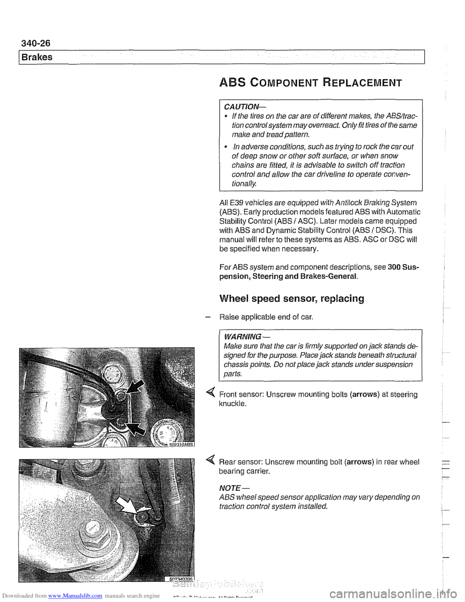
< Front sensor: Unscrew mounting bolts (arrows) at steering
knuckle.
4 Rear sensor: Unscrew mounting bolt (arrows) in rear wheel
bearing carrier.
NOTE-
ABS wheelspeed sensor application may vary depending on
traction control system installed.
Page 789 of 1002
Downloaded from www.Manualslib.com manuals search engine
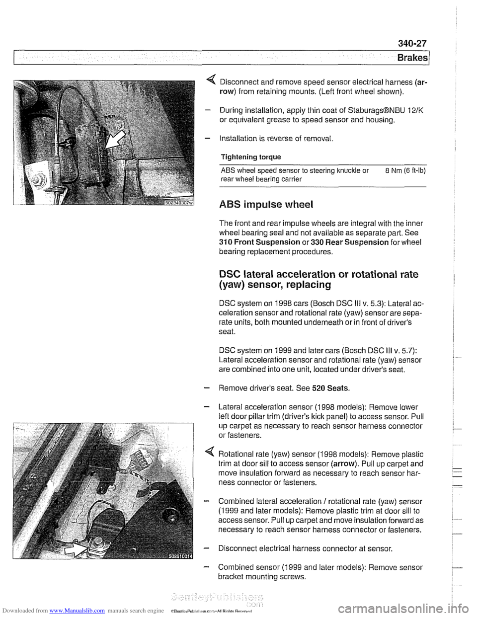
4 Disconnect and remove speed sensor electrical harness (ar-
row) from retaining mounts. (Lefl front wheel shown).
- During installation, apply thin coat of StaburagsBNBU 12/K
or equivalent grease to speed sensor and housing.
- Installation is reverse of removal.
Tightening torque
ABS wheel speed sensor to steering knuckle or 8 Nm (6 It-lb)
rear wheel bearing carrier
ABS impulse wheel
The front and rear impulse wheels are integral with the inner
wheel bearing seal and not available as separate part. See
310 Front Suspension or 330 Rear Suspension for wheel
bearing replacement procedures.
DSC lateral acceleration or rotational rate
(yaw) sensor, replacing
DSC system on 1998 cars (Bosch DSC Ill v. 5.3): Lateral ac-
celeration sensor and rotational rate (yaw) sensor are sepa-
rate units, both mounted underneath or in front of driver's
seat.
DSC system on 1999 and later cars (Bosch DSC
Ill v. 5.7):
Lateral acceleration sensor and rotational rate (yaw) sensor
are combined into one unit, located under driver's seat.
- Remove driver's seat. See 520 Seats.
- Lateral acceleration sensor (1 998 models): Remove lower
lefl door pillar trim (driver's
kick panel) to access sensor. Pull
up carpet as necessary to reach sensor harness connector
or fasteners.
4 Rotational rate (yaw) sensor (1998 models): Remove plastic
trim at door sill to access sensor (arrow). Pull up carpet and
move insulation forward as necessary to reach sensor har-
ness connector or fasteners.
- Combined lateral acceleration / rotational rate (yaw) sensor
(1 999 and later models): Remove plastic trim at door sill to
access sensor. Pull up carpet and move insulation forward as
necessary to reach sensor harness connector or fasteners.
- Disconnect electrical harness connector at sensor.
- Combined sensor (1 999 and later models): Remove sensor
bracket mounting screws.
Page 910 of 1002
Downloaded from www.Manualslib.com manuals search engine
51 5-1 6
Central Locking and Anti-Theft
DOOR HANDLES AND LOCKS
In the procedures that follow, door handle removal, door lock
cylinder removal and door latch removal are covered for the
left front door. Other doors are similar although simpler, due
to the
lack of lock cylinder.
Inside door release removal is covered in the procedure for
inner door
ane el removal. See 411 Doors.
Door handle (outer), removing and
installing
NOTE-
IfBMWspecial tools 51 3201 and51 3 203 are available, the
door handle can be removed without removing the door trim
panel or door
airbag. Use the access hole behind the rubber
sealing plug on the door edge.
- Close window on front door.
- Disconnect battery negative (-) cable.
CAUTlOG
Prior to disconnecting the batter)! read the battery discon-
nection cautions given
in 001 General Warnings and Cau-
tions.
Remove front door trim panel. See 411 Doors.
Remove door-mounted air bag. See 721
Airbag System
(SRS).
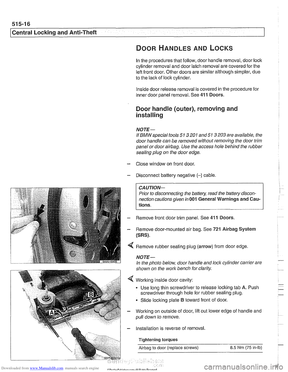
Remove rubber sealing plug (arrow) from door edge
NOTE-
In the photo below, door handle and lock cylinder carrier are
shown on the work bench for clarity.
Working inside door cavity:
- Use long thin screwdriver to release locking tab A. Push
screwdriver through hole for rubber sealing plug.
Slide locking plate
B toward front of door.
Working on outside of door, lift out lower edge of handle and
pull down to remove.
Installation is reverse of removal,
Tightening torques
Airbag to door (replace screws) 8.5 Nrn (75 in-lb)
Page 913 of 1002
Downloaded from www.Manualslib.com manuals search engine
Central Locking and Anti-Theft
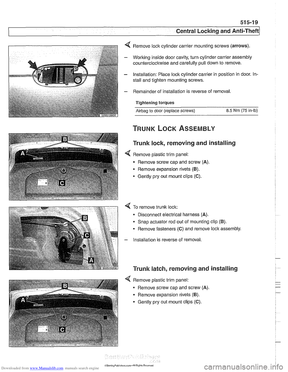
4 Remove lock cylinder carrier mounting screws (arrows).
- Working inside door cavity, turn cylinder carrier assembly
counterclockwise and carefully pull down to remove.
- Installation: Place lock cylinder carrier in position in door. In-
stall and tighten mounting screws.
- Remainder of installation is reverse of removal.
Tightening torques
Airbag to door (replace screws) 8.5 Nm (75 in-lb)
Trunk lock, removing and installing
< Remove plastic trim panel:
- Remove screw cap and screw (A).
Remove expansion rivets (B).
* Gently pry out mount clips (C).
4 To remove trunk lock:
Disconnect electrical harness
(A).
* Snap actuator rod out of mounting clip (B).
Remove fasteners (C) and remove lock assembly.
- Installation is reverse of removal
Trunk latch, removing and installing
4 Remove plastic trim panel:
Remove screw cap and screw
(A).
Remove expansion rivets (B).
Gently pry out mount clips (C).
Page 933 of 1002
Downloaded from www.Manualslib.com manuals search engine
Sunroof, adjusting
The sunroof is controlled by a set of cables that move the sun-
roof panel along guide rails when the motor is operated. The
sunroof can be adjusted without removing it from the car.
NOTE-
Be sure to check drains in front corners of sunroof carrier if
water is entering car through headliner.
- The sunroof panel should be adjusted under the following cir-
cumstances:
Sunroof misaligned with roof.
Sunroof does not close squarely.
* Wind noise at high speeds (sunroof closed).
Sunroof has been removed.
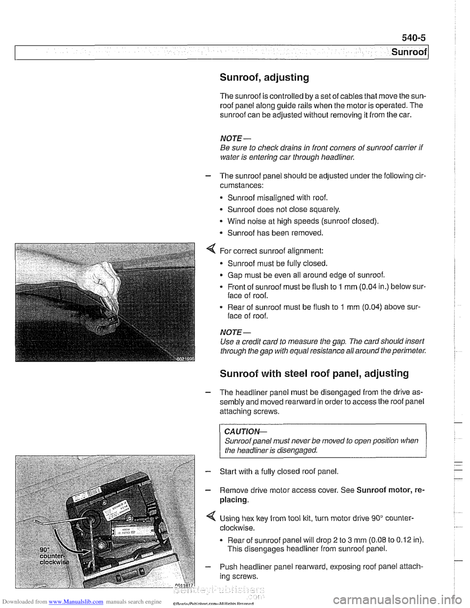
For correct sunroof alignment:
Sunroof must be fully closed.
Gap must be even all around edge of sunroof.
Front of sunroof must be flush to
1 mm (0.04 in.) below sur-
face of roof.
. Rear of sunroof must be flush to 1 mm (0.04) above sur-
face of roof.
NOTE-
Use a credit card to measure the gap. The card sllould insert
through the gap with equal resistance all around the perimeter.
Sunroof with steel roof panel, adjusting
- The headliner panel must be disengaged from the drive as-
sembly and moved rearward in order to access the roof panel
attaching screws.
CAUTIOI\C
Sunroof panel must never be moved to open position when . .
I the headliner is disenaaaed. 1
- Start with a fully closed roof panel.
- Remove drive motor access cover. See Sunroof motor, re-
placing.
Using hex key from tool kit, turn motor drive 90" counter-
clockwise.
Rear of sunroof panel will drop
2 to 3 mm (0.08 to 0.12 in).
This disengages headliner from sunroof panel.
- Push headliner panel rearward, exposing roof panel attach-
ing screws.
Page 938 of 1002
Downloaded from www.Manualslib.com manuals search engine
.-
Sunroof
Sunroof motor, replacing
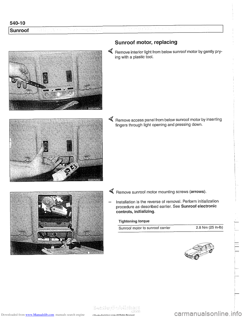
Remove interior light from below sunroof motor by gently pry-
ing with a plastic tool.
4 Remove access panel from below sunroof motor by inserting
fingers through light opening and pressing down.
4 Remove sunroof motor mounting screws (arrows).
- Installation is the reverse of removal. Perform initialization
procedure as described earlier. See Sunroof electronic
controls, initializing.
Tightening
torque
Sunroof motor to sunroof carrier 2.8 Nm (25 in-lb)