Antenna amplifier BMW 540i 1997 E39 Workshop Manual
[x] Cancel search | Manufacturer: BMW, Model Year: 1997, Model line: 540i, Model: BMW 540i 1997 E39Pages: 1002
Page 800 of 1002

Downloaded from www.Manualslib.com manuals search engine
.
I Body-General 1
Rear wiper system
The rear wiper assembly on the E39 Sport Wagon is a self-
contained unit. The control electronics are integrated into the
gear drive that is part of the motor assembly. The control elec-
tronics contain two hall sensors, one
forthe park position and
one
forthe end stop or to signal reverse direction of the wiper
motor.
-
Wiperlwasher
stalk switch
/ 4 - 3
502400100
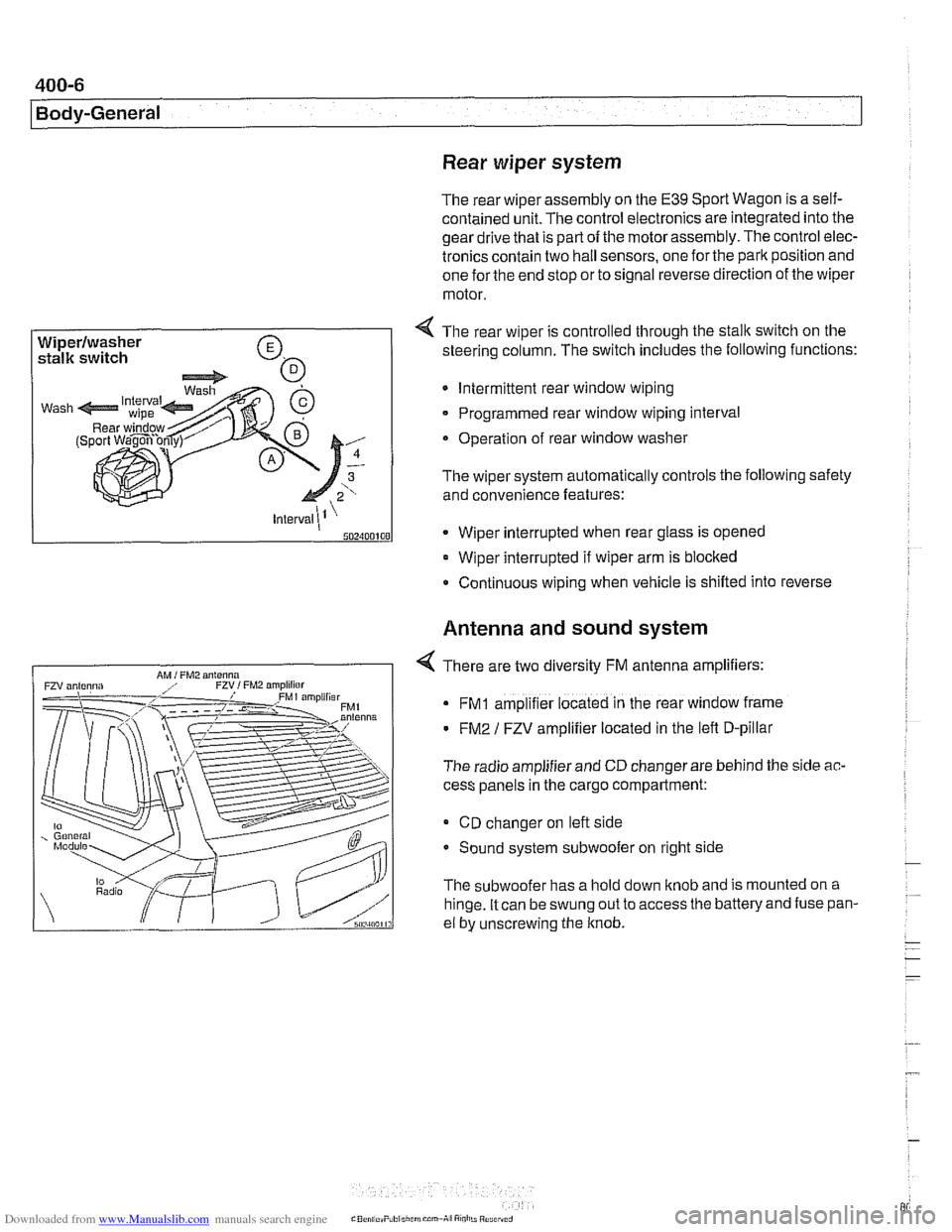
4 The rear wiper is controlled through the stalk switch on the
steering column. The switch includes the following functions:
Intermittent rear window wiping
Programmed rear window wiping interval
Operation of rear window washer
The wiper system automatically controls the following safety
and convenience features:
* Wiper interrupted when rear glass is opened
Wiper interrupted if wiper arm is blocked
Continuous wiping when vehicle is shifled into reverse
Antenna and sound system
4 There are two diversity FM antenna amplifiers:
FMI amplifier located in the rear window frame
FM2 / FZV amplifier located in the lefl D-pillar
The radio amplifier and CD changer are behind the side
ac-
cess panels in the cargo compartment:
CD changer on lefl side
Sound system subwoofer on right side
The subwoofer has a hold down knob and is mounted on a
hinge. It can be swung out to access
the batteryand fuse pan-
el by unscrewing the knob.
Page 839 of 1002

Downloaded from www.Manualslib.com manuals search engine
Trunk Lid, Tailgate
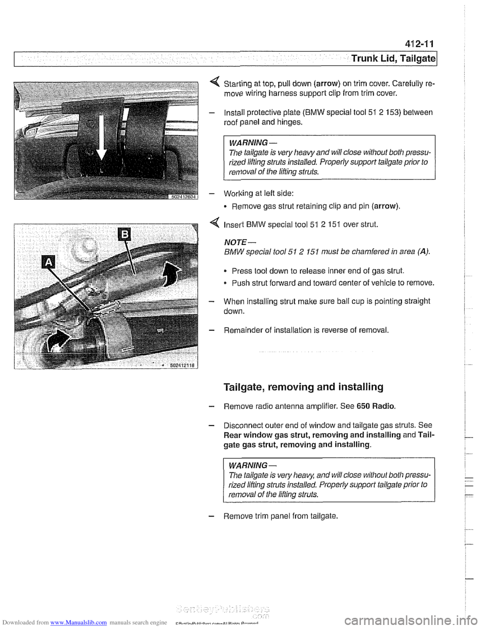
Starting at top, pull down (arrow) on trim cover. Carefully re-
move wiring harness support clip from trim cover.
Install protective plate
(BMW special tool 51 2 153) between
roof panel and hinges.
WARNING -
The tailgate is very heavy and will close without both pressu-
rized lifting
struts installed. Properly support tailgate prior to
removal of the lifting struts.
Worlting at left side:
Remove gas strut retaining clip and pin (arrow).
4 Insert BMW special tool 51 2 151 over strut.
NOTE-
BMW special tool 51 2 151 must be chamfered in area (A).
Press tool down to release inner end of gas strut.
Push strut forward and toward center of vehicle to remove.
- When installing strut make sure ball cup is pointing straight
down.
- Remainder of installation is reverse of removal.
Tailgate, removing and installing
- Remove radio antenna amplifier. See 650 Radio.
- Disconnect outer end of window and tailgate gas struts. See
Rear window gas strut, removing and installing and Tail-
gate gas strut, removing and installing.
WARNING-
The tailgate is very heaq and will close without both pressu-
rized lifling struts installed. Properly support tailgate prior to
removal of the lifling struts.
- Remove trim panel from tailgate.
Page 991 of 1002

Downloaded from www.Manualslib.com manuals search engine
INDEX 'tl
WARNING
Your common sense, good
judgemenl, and general alertness are
crucial to sale and successiul service
worlr. Belore attempting any work on
your
BMM be sure lo read 001
General Warnings and Cautions
and the
copyriglll page at the front 01
the manual. Review these warnings
and
caulions each lime you prepare
lo work on your BMW. Please also
read any warnings and cautions that
accompany
tile procedures in the
manual.
312-way valve (running losses)
see Fuel tank
Abbreviations, commonly used 600-14
ABS (antilock brake system)
see
Bral(es
A/C air distribution motors
see stepper motors (below)
blower final stage (resistor pack),
replacing
640-16
blower, removinglinslalling
640-1 5
compressor, replacing
640-24 condenser, replacing 64045
control panellmodule, removing1
installing
640-1 1
evaporakr, removinglinstalling 640-29
evaporator temperature sensor
640-12 expansion valve, removinglinstailing
640-27
IHKA/ IHKR system description 640-5
receiveridrier, replacing 640-26
stepper motors 640-1 3 ventilation microiilter, replacing
020-22. 640-17
see also Heating
Accelerator
iinlcage
see Maintenance
Activated carbon canister
see Fuel tank
ADS (auxiliary throttle valve)
130-57
Air compressor
330-44
Air conditioning
see
AIC
Air distribution (flap) motors
seeNC, stepper motors
Air filter see Maintenance
Air spring
300-6, 330-12
Airbag system (SRS)
2-stage
airbag 721-4
control module, replacing 721-7 driver airbag, removinglinstalling
721-8
iiead protection airbag 721-12 components 721-1 1
indicator
lighl721-4
passenger airbag, removinglinstalling
721-9 side-impact airbags crash sensor,
replacing
721-7
Airflow sensor see 130 under appropriate
fuel
injection system
Air pump
see 130 under appropriate fuel
injection system, secondary air
injection system
Air suspension
see Electronic height control
(EHC)
Alarm
see Anti-theft alarm
Alignment see
Wheei alignment
Aluminum suspension components
300-2
Antenna 650-6
Alternator see Battery, starter, alte rnator
Amplifier
650-4
Anti-theft alarm (DWA)
515-24 emergency disarming 515-31
Antifreeze (engine coolant)
see Maintenance
see also Cooling system
Antilock brake system (ABS) see Brakes
ASC see Brakes
ATF (automatic transmission fluid)
see Automatic transmission
see also Cooling systern
Automatic headlight adjustmenl
(LWR) see Lights
Automatic seat belt tensioner
720-4
Automatic shiftloclc
see
Gearshift
Automatic transmission
applications
200-3, 240-4
ATF 020-10, 200-4
capacity 240-8 checking 240-6
drainingifilling 240-7
heat exchanger 170-5
fluid pan and strainer 240-9 gearshift
see Gearshift
ID tag
200-3 range switch 610-6
removaliinstallation 240-10
steptronic see Gearshift
Auxiliary cooling fan
see
Coollng system, electric Ian
Auxiliary throttle valve (ADS)
130-57
Axle joint
see Drive axle
Back-up light switch
automatic transmission see Automatic transmission. range switch
- .~.~~~
manual transmission 230-8 -
- I