CARRIER BEARING BMW 540i 1997 E39 Workshop Manual
[x] Cancel search | Manufacturer: BMW, Model Year: 1997, Model line: 540i, Model: BMW 540i 1997 E39Pages: 1002
Page 134 of 1002
Downloaded from www.Manualslib.com manuals search engine
11 3-40
I Cylinder Head Removal and Installation
Lubricate camshafts, camshaft carriers, bearing caps, hy-
draulic lifters, friction washers, splined shafts and spline hubs
with assembly lubricant before installation.
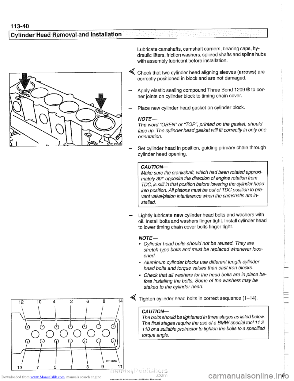
4 Check that two cylinder head aligning sleeves (arrows) are
correctly positioned in block and are not damaged.
- Apply elastic sealing compound Three Bond 1209 8 to cor-
ner joints on cylinder block to timing chain cover.
- Place new cylinder head gasket on cylinder block.
NOTE-
The word "OBEN" or "TOP printed on the gasket, should
face up. The cylinder headgaslet will fit correctly in only one
orientation.
- Set cylinder head in position, guiding primary chain through
cylinder head opening.
CAUJION-
Make sure the crankshaft, which had been rotated approxi-
mately 30" opposite the direction of engine rotation from
TDC, is still in thatposition before lowering the cylinder head
into position. All pistons must be out of TDC position to pre-
vent
valve/piston interference when the camshafts are in-
stalled.
- Lightly lubricate new cylinder head bolts and washers with
oil. Install bolts and washers finger tight. Install cylinder head
to lower timing chain cover bolts finger tight.
NOJE-
Cylinder head bolts should not be reused. They are
stretch-type bolts and must be replaced whenever loos-
ened.
* Aluminum cylinder blocls use different length cylinder
head bolts and torque values than cast iron blocks.
Check that all washers for
Nle head bolts are in place be-
fore installing the bolts. Some of the washers may be
staked to the cylinder head.
I 12 10 4 2 6 8 141 Tighten cylinder head bolts in correct sequence (1-14)
CA U TIOW-
The bolts should be tightened in three stages as listed below
The final stages require the use of a BMW special tool
11 2
110 or a suitable protractor to tighten the bolts to a specified
torque angle.
Page 136 of 1002
Downloaded from www.Manualslib.com manuals search engine
1 13-42
I Cylinder Head Removal and Installation
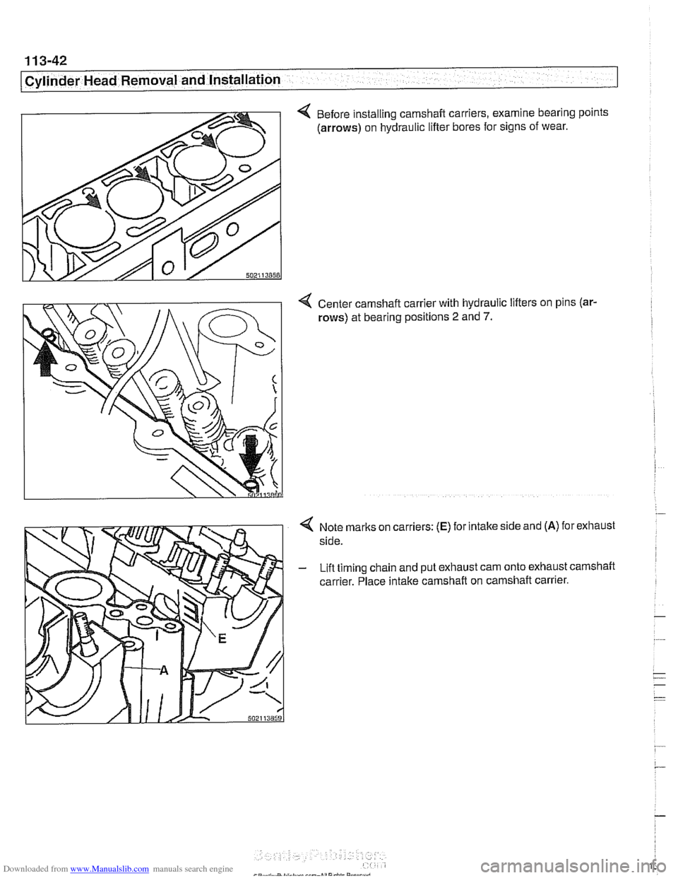
4 Before installing camshaft carriers, examine bearing points
(arrows) on hydraulic lifter bores for signs of wear.
4 Center camshaft carrier with hydraulic lifters on pins (ar-
rows) at bearing positions 2 and 7.
Note marks on carriers: (E) for intake side and (A) for exhaust
side.
Lift timing chain and put exhaust cam onto exhaust camshaft
carrier. Place intake camshaft on camshaft carrier.
Page 181 of 1002
Downloaded from www.Manualslib.com manuals search engine
11 6-5
I Cylinder Head and valvetrain1
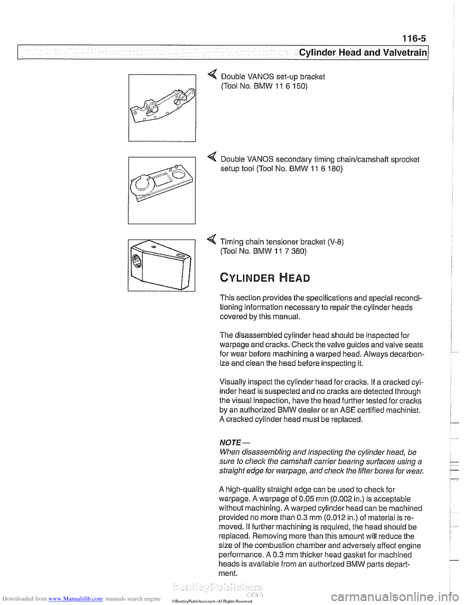
4 Timing chain tensioner bracket (V-8)
(Tool No. BMW
11 7 380)
CYLINDER HEAD
This section provides the specifications and special recondi-
tioning information necessary to repair the cylinder heads
covered by this manual.
The disassembled cylinder head should be inspected for
warpage and cracks. Check the valve guides and valve seats
for wear before machining a warped head. Always decarbon-
ize and clean the head before inspecting it.
Visually inspect the cylinder head for craclts.
If a cracked cyl-
inder head is suspected and no
craclts are detected through
the visual Inspection, have the head further tested for cracks
by an authorized BMW dealer or an ASE certified machinist.
A cracked cylinder head must be replaced.
NOJE-
When disassembling and inspecting the cylinder head, be
sure to
checlc the camshaft carrier bearing surfaces using a
straight edge for
warpage, and check the lifter bores for wear.
A high-quality straight edge can be used to
checlc for
warpage. A warpage of 0.05 mm (0.002 in.) is acceptable
without machining. A warped cylinder head can be machined
provided no more than 0.3
mm (0.012 in.) of material is re-
moved.
If further machining is required, the head should be
replaced. Removing more than this amount will reduce the
size of the combustion chamber and adversely affect engine
performance. A 0.3 mm
thicker head gasket for machined
heads is available from an authorized BMW parts depart-
ment.
Page 193 of 1002

Downloaded from www.Manualslib.com manuals search engine
Cylinder Head and Valvetrain
4 Secure hydraulic lifters in lifter bores using BMW special tool
11 3 250, or remove lifters using a magnetic pick-up tool.
4 Remove camshaft bearing carrier from cylinder head.
CA UTION-
Camshaftbearing carriers must be reinstalledin their original
/ locations (E for ir;fal
Do not let hydraulic lifters fall out as the camshaft carrier is
removed.
Hydraulic lifters should be stored in an upright position.
Used hydraulic lifters
must be replaced into original lifter
bores.
Camshafts and lifters, installing
(M52 Engine)
Lubricate camshafts, camshaft carriers, bearing caps, hy-
draulic liflers, friction washers, splined shafts and spline hubs
with assembly lubricant before installation.
Make sure
the cranltshaft, which had been rotated approxi-
mately
30" opposite the direction of engine rotation from
TDC, is still in thatposition before lowering the
camshaffs into
position. All pistons must be out of TDC position to prevent
valve/piston interference when the camshalts are installed.
Before installing camshaft carriers, examine bearing bores
(arrows) on hydraulic lifter bores for signs of wear.
Page 194 of 1002
Downloaded from www.Manualslib.com manuals search engine
116-18
Cylinder Head and Valvetrain
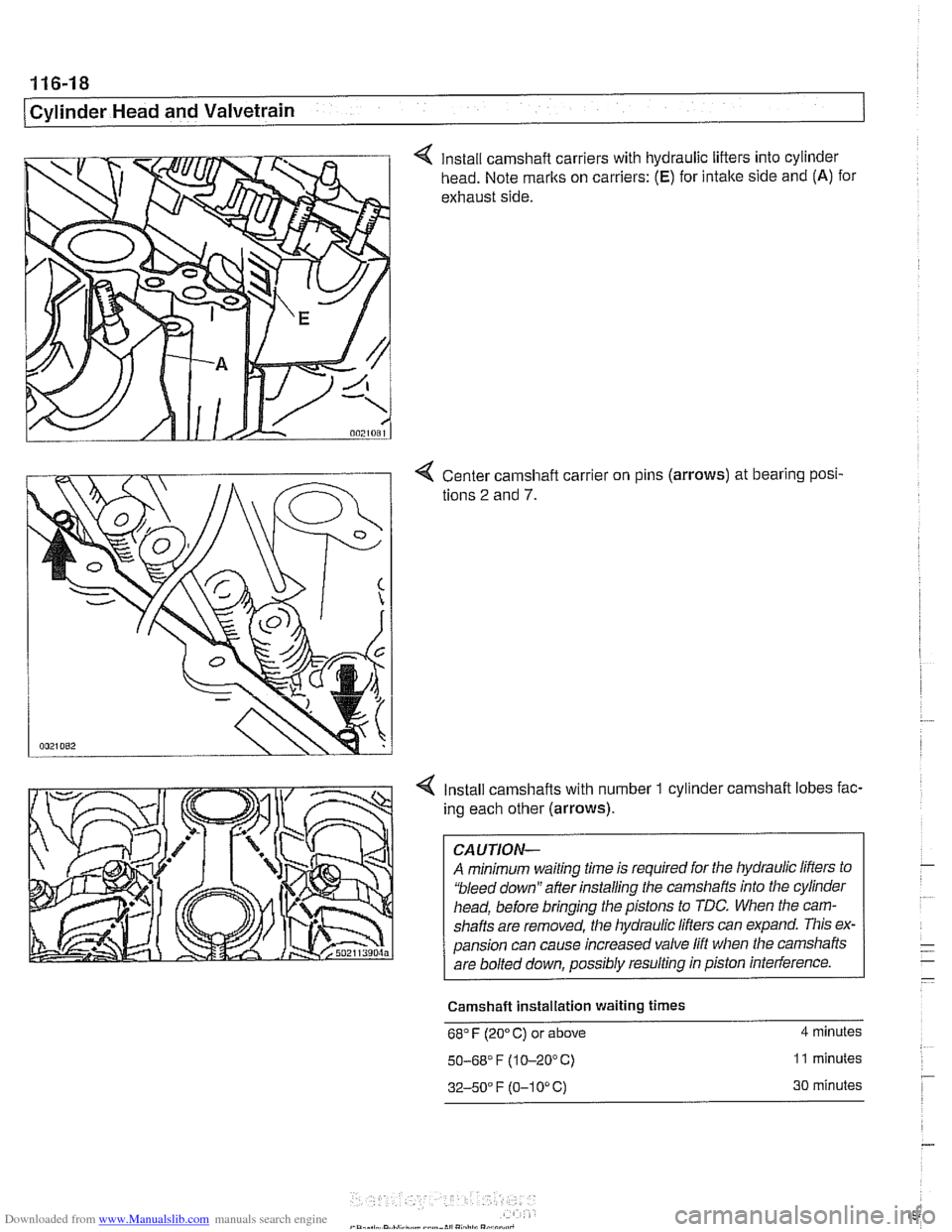
4 Install camshaft carriers with hydraulic lifters into cylinder
head. Note marks on carriers:
(E) for intake side and (A) for
exhaust side.
4 Center camshaft carrier on pins (arrows) at bearing posi-
tions
2 and 7.
4 Install camshafts with number 1 cylinder camshaft lobes fac-
ing each other (arrows).
CAUTION-
A minimum waiting time is required for the hydraulic lifters to
'bleed down" after installing the camshafts into the cylinder
head, before bringing the pistons to TDC. When the cam-
shafts are removed, the hydraulic
lifers can expand. This ex-
pansion can cause increased valve lift when the camshafts
are bolted down, possibly resulting in piston interference.
Camshaft Installation waiting
times
68" F (20" C) or above 4 minutes
50-68' F (1 0-20°C) 11 minutes
32-50" F (0-1 0" C) 30 minutes
Page 201 of 1002
Downloaded from www.Manualslib.com manuals search engine
Cylinder Head and Valvetrain
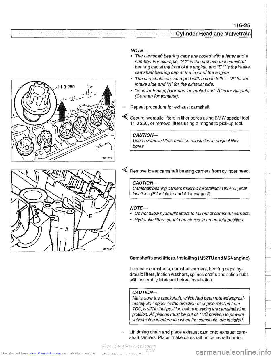
NOTE-
The camshaft bearing caps are coded with a letter and a
number. For example, "A
1" is the first exhaust camshaft
bearing cap
at the front of the engine, and "El "is the intake
camshaft bearing cap at the front of the engine.
-. -
The camshafts are stamped with a code letter - "E for the
intake side and
'X" for the exhaust side.
"E is for Einlap. (German for intake) and 'XA7s for Auspuff.
(German for exhaust).
- Repeat procedure for exhaust camshaft
< Secure hydraulic lifters in lifter bores using BMW special tool
11 3 250, or remove lifters using a magnetic pick-up tool.
I CAUTION-
Used liydraulic lifters must be reinstalled in original lifter
1 bores.
4 Remove lower camshaft bearing carriers from cylinder head.
CAUTION- Camshaft bearing carriers must be reinstalled in their original
locations
(E for intalce and A for exhaust).
NOTE- Do not allow hydraulic lifters to fall out of camshaft carriers.
Hydraulic lifters should be stored in an upright position.
Camshafts and lifters, installing (M52TU and M54 engine)
Lubricate camshafts, camshaft carriers, bearing caps, hy-
draulic lifters, friction washers, splined shafts and
spline hubs
with assembly
lubricant before installation.
CAUTION-
Make sure the crankshaft, which had been rotated approxi-
mately
30" opposite the direction of engine rotation from
TDC, is
stillin thatposition before lowering the camshafts into
position. Allpistons must be out of
TDCposition to prevent
valve/piston inteiference when the carnshafis are installed.
- Lift timing chain and place exhaust cam onto exhaust cam-
shaft carriers. Place
intake camshaft on camshaft carrier.
Page 202 of 1002
Downloaded from www.Manualslib.com manuals search engine
11 6-26
I Cylinder Head and Valvetrain
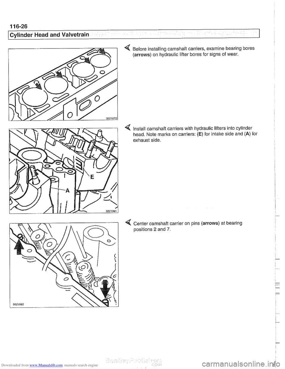
4 Before installing camshaft carriers, examine bearing bores
(arrows) on hydraulic lifter bores for signs of wear.
Install camshaft carriers with hydraulic lifters into cylinder
head. Note marks on carriers:
(E) for intake side and (A) for
exhaust side.
4 Center camshaft carrier on pins (arrows) at bearing
aositions 2 and 7.
Page 625 of 1002
Downloaded from www.Manualslib.com manuals search engine
300-5
Suspension, Steering and Brakes - ~enerall
The E39 rear suspension subframe is used as a rigid mount-
ing platform
forthe differential (also called final drive) and rear
suspension components. The differential is mounted to the
subframe and the subframe is bolted to the body through rub-
ber bushings which help isolate drivetrain noise and vibration.
The
€39 rear suspension is known as a modified multi-link
system. Three control arms on each side locate the rear
wheels.
The lowercontrol arm, called the swing arm, is attached to the
wheel bearing carrier through a pivoting integral link.
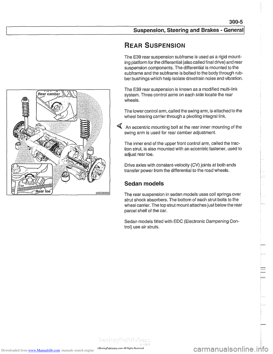
An eccentric mounting bolt at the rear inner mounting of the
swing arm is used for rear camber adjustment.
The inner end of the upper front control arm, called the trac-
tion strut, is also mounted with an eccentric fastener, used to
adjust rear toe.
Drive axles with constant-velocity (CV) joints at both ends
transfer power
from the differential to the road wheels.
Sedan models
The rear suspension in sedan models uses coil springs over
strut shock absorbers. The bottom of each strut bolts to the
wheel
carrier.The top strut mount attaches just below the rear
parcel shelf of the car.
Sedan models fitted with EDC (Electronic Dampening Con-
trol) use air struts.
Page 626 of 1002
Downloaded from www.Manualslib.com manuals search engine
300-6
/Suspension, Steering and Brakes - General
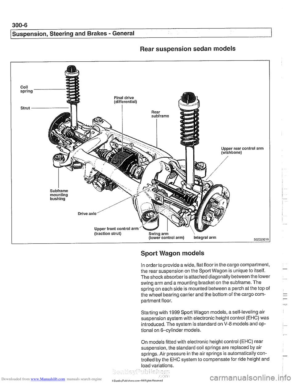
Rear suspension sedan models
Coil spring
Strut
-
'01 arm
Sport Wagon models
In order to provide a wide, ilat iloor in the cargo compartment,
the rear suspension on the Sport Wagon is unique to itself.
The shoclcabsorber is attached diagonally between the lower
swing arm and a mounting bracket on the subframe. The
spring on each side is mounted between a perch at the top
oi
the wheel bearing carrier and the bottom of the cargo com-
partment floor.
Starting with
1999 Sporl Wagon models, a self-leveling air
suspension system with electronic height control (EHC) was introduced. The system is standard on
V-8 models and op-
tional on 6-cylinder models.
On models fitted with electronic height control (EHC) rear
suspension, the standard coil springs are replaced by air
springs. Air pressure in the air springs is automatically con-
trolled by the
EHC system to compensate for ride height and
load variations.
Page 697 of 1002
Downloaded from www.Manualslib.com manuals search engine
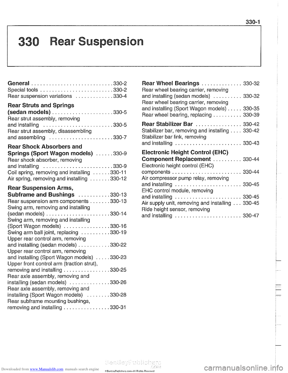
330 Rear Suspension
General . . . . . . . . . . . . . . . . . . . . . . . . . . . ,330-2
Special tools . . . . . . . . . . . . . . . . . . . . . . . . ,330-2
Rear suspension variations . . . . . . . . . . . . ,330-4
Rear Struts and Springs
(sedan models)
. . . . . . . . . . . . . . . . . . . . ,330-5
Rear strut assembly, removing
and installing
. . . . . . . . . . . . . . . . . . . . . . . ,330-5
Rear strut assembly, disassembling
and assembling
. . . . . . . . . . . . . . . . . . . . . ,330-7
Rear Shock Absorbers and
Springs (Sport Wagon models)
. . . . . ,330-9
Rear shock absorber, removing
and installing
. . . . . . . . . . . . . . . . . . . . . . . ,330-9
Coil spring, removing and installing . . . . . ,330-1 1
Air spring, removing and installing
. . . . . . ,330-12
Rear Suspension Arms,
Subframe and Bushings . . . . . . . . . . ,330-13
Rear suspension arm components . . . . . . ,330-1 3
Swing arm, removing and installing (sedan models)
. . . . . . . . . . . . . . . . . . . . . ,330-1 4
Swing arm, removing and installing (Sport Wagon models)
. . . . . . . . . . . . . . . ,330-16
Swing arm ball joint, replacing . . . . . . . . . ,330-1 9
Upper rear control arm, removing
and installing (sedan models)
. . . . . . . . . . .330-22
Upper rear control arm, removing
and installing (Sport Wagon models)
. . . . .330-23
Upper front control arm (traction strut),
removing and installing
. . . . . . . . . . . . . . . ,330-25
Rear axle assembly, removing and
installing (sedan models)
. . . . . . . . . . . . . ,330-26
Rear axle assembly, removing and
installing (Sport Wagon models)
. . . . . . . ,330-28
Rear subframe mounting bushings,
removing and installing
. . . . . . . . . . . . . . . .330-31
Rear Wheel Bearings . . . . . . . . . . .
Rear wheel bearing carrier, removing
and installing (sedan models)
. . . . . . .
Rear wheel bearing carrier, removing
and installing (Sport Wagon models)
. .
Rear wheel bearing, replacing . . . . . . .
Rear Stabilizer Bar
Stabilizer bar, removing and installing .
Stabilizer bar link, removing
and installing
. . . . . . . . . . . . . . . . . . . .
Electronic Height Control (EHC)
Component Replacement
. . . . . . .
Electronic height control (EHC)
components
.....................
Air compressor pump relay, removing
and installing
. . . . . . . . . . . . . . . . . . . .
EHC control module, removing
and installing
. . . . . . . . . . . . . . . . . . . .
Air supply unit, removing and installing
Ride height sensor, removing
and installing
. . . . . . . . . . . . . . . . . . . .