THROTTLE PEDAL BMW 540i 1997 E39 Workshop Manual
[x] Cancel search | Manufacturer: BMW, Model Year: 1997, Model line: 540i, Model: BMW 540i 1997 E39Pages: 1002
Page 69 of 1002
Downloaded from www.Manualslib.com manuals search engine
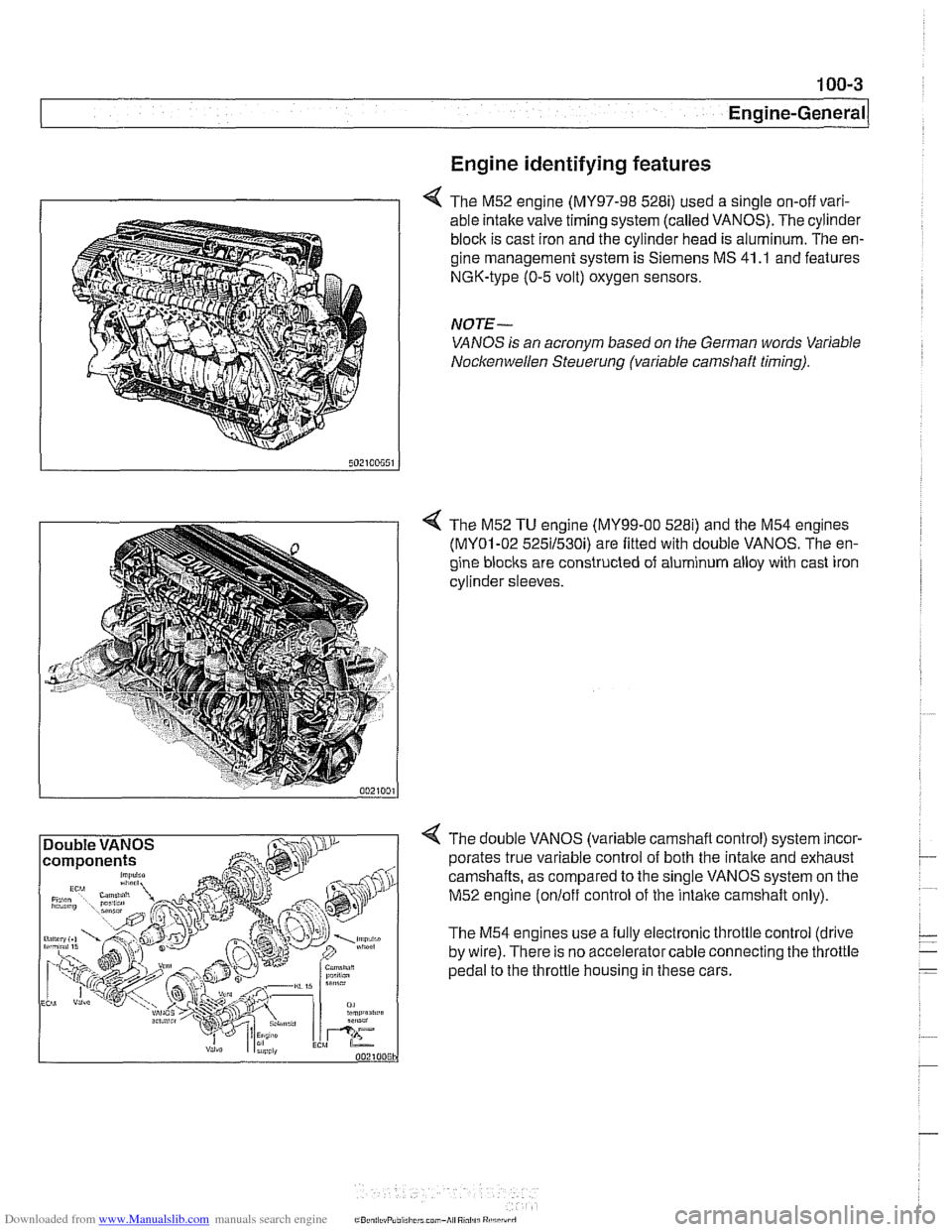
Engine identifying features
4 The M52 engine (MY97-98 528i) used a single on-off vari-
able intake valve timing system (called VANOS). The cylinder
block is cast iron and the cylinder head is aluminum. The en-
gine management system is Siemens MS 41
.I and features
NGK-type (0-5 volt) oxygen sensors.
NOTE-
VANOS is an acronym based on the German words Variable
Nocltenwellen Steuerung (variable camshaft timing).
4 The M52 TU engine (MY99-00 5281) and the M54 engines
(MY01-02 525il530i) are fitted with double VANOS. The en-
gine
blocits are constructed of aluminum alloy with cast iron
cylinder sleeves.
4 The double VANOS (variable camshaft control) system incor-
porates true variable control of both the
intake and exhaust
camshafts, as compared to the single VANOS system on the
M52 engine
(onloff control of the intaite camshaft only).
The M54 engines use a fully electronic throttle control (drive
by wire). There is no accelerator cable connecting the throttle
pedal to the throttle housing in these cars.
Page 70 of 1002
Downloaded from www.Manualslib.com manuals search engine
100-4
I Engine-General
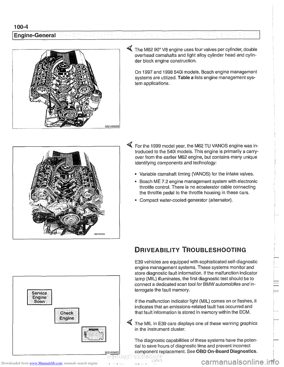
The M62 90" V8 engine uses four valves per cylinder, double
overhead camshafts and light alloy cylinder head and cylin-
der
bloclc engine construction.
On 1997 and 1998 540i models, Bosch engine management
systems are utilized. Table a lists engine management sys-
tem applications.
4 For the 1999 model year, the M62 TU VANOS engine was in-
troduced to the 540i models. This engine is primarily a carry-
over from the earlier M62 engine, but contains many unique
identifying components and technology:
Variable camshaft timing (VANOS) for the intake valves.
Bosch ME 7.2 engine management system with electronic
throttle control. There is no accelerator cable connecting
the throttle pedal to the throttle housing in these cars.
Compact water-cooled generator (alternator).
E39 vehicles are equipped with sophisticated self-diagnostic
engine management systems. These systems monitor and
store diagnostic fault information. If the malfunction indicator
lamp (MIL) illuminates, the first diagnostic test should be to
connect a dedicated scan tool for BMW automobiles and in-
terrogate the fault memory.
If the malfunction indicator light (MIL) comes on orflashes, it
indicates that an emissions-related fault has occurred and
that fault information is stored in memory within the ECM.
4 The MIL in E39 cars displays one of these warning graphics
in the instrument cluster.
The diagnostic capabilities of these systems have the poten-
tial to save hours of diagnostic time and prevent incorrect
5 placement. See OBD On-Board Diagnostics.
Page 399 of 1002
Downloaded from www.Manualslib.com manuals search engine
Fuel Injection I
Mass air flow (MAF) sensor,
checking and replacing
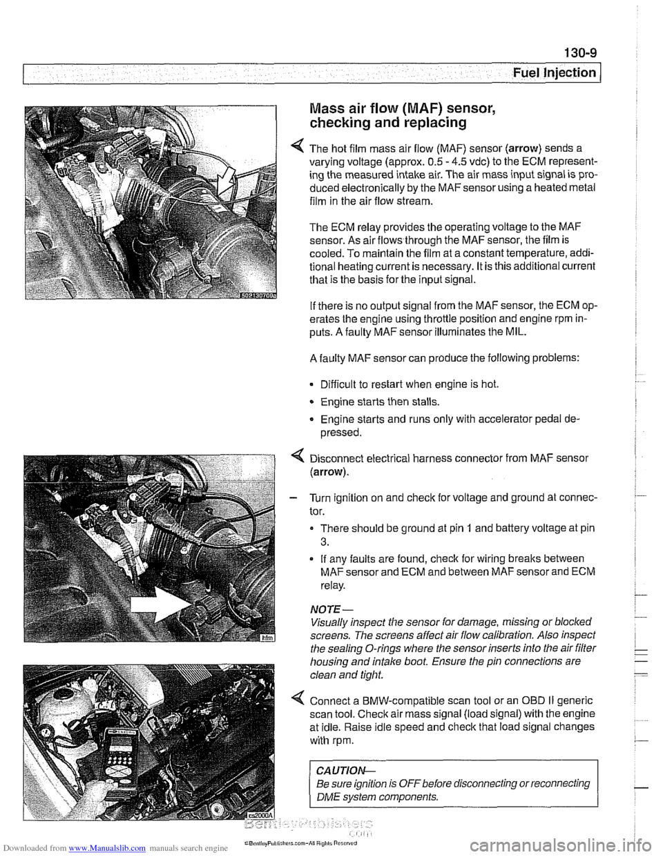
4 The hot film mass air flow (MAF) sensor (arrow) sends a
varying voltage (approx.
0.5 - 4.5 vdc) to the ECM represent-
ing the measured intake air. The air mass input signal is pro-
duced electronically by the
MAFsensorusing a heated metal
film in the air flow stream.
The ECM relay provides the operating voltage to the MAF
sensor. As air flows through the MAF sensor, the film is
-
cooled. To maintain the film at a constant temperature, addi-
tional heating current is necessary. It is this additional current
that is the basis for the input signal.
If there is no output signal from the MAF sensor, the ECM op-
erates the engine using throttle position and engine rpm in-
puts. A faulty MAF sensor illuminates the MIL.
A faulty MAF sensor can produce the following problems:
Difficult to restart when engine is hot.
Engine starts then stalls.
Engine starts and runs only with accelerator pedal de-
pressed.
Disconnect electrical harness connector from MAF sensor
(arrow).
- Turn ignition on and check for voltage and ground at connec-
tor.
There should be ground at pin
1 and battery voltage at pin
3.
If any faults are found, check for wiring breaks between
MAF sensor and ECM and between MAF sensor and ECM
relay.
NOTE-
Visually inspect the sensor for damage, missing or blocked
screens. The screens affect air flow calibration. Also inspect
the sealing O-rings where the sensor inserts into the air
filter
housing and intake boot. Ensure the pin connections are
clean and tight.
4 Connect a BMW-compatible scan tool or an OBD II generic
scan tool. Check air mass signal (load signal) with the engine
at idle. Raise idle speed and check that load signal changes
with rpm.
CA UTIOI\C
Be sure ignition is OFFbefore disconnecting or reconnecting r
1 DME svstem components. 1
Page 422 of 1002
Downloaded from www.Manualslib.com manuals search engine
Fuel Injection
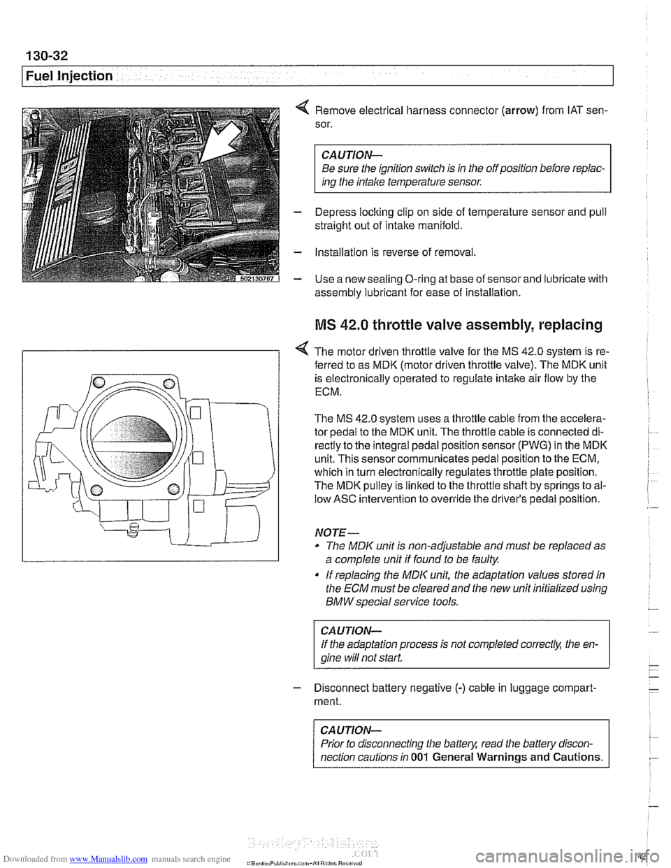
4 Remove electrical harness connector (arrow) from IAT sen-
sor.
CAUTION-
Be sure the ignition switch is in the off position before repiac-
ins the intake temperature sensor.
- Depress loclting clip on side of temperature sensor and pull
straight out of intake manifold.
- Installation is reverse of removal
- Use a new sealing O-ring at base of sensor and lubricate with
assembly lubricant for
ease of installation
MS 42.0 throttle valve assembly, replacing
< The motor driven throttle valve for the MS 42.0 system is re-
- ferred to as MDK (motor driven throttle valve). The MDK unit
is electronically operated to regulate intake air flow by the
ECM.
The
MS 42.0 system uses a throttle cable from the accelera-
tor pedal to the MDK unit. The throttle cable is connected di-
rectly to the integral pedal position sensor
(PWG) in the MDK
unit. This sensor communicates pedal position to the ECM,
which in turn electronically regulates throttle plate position.
The MDK pulley is linked to the throttle shaft by springs to al-
low ASC intervention to override the driver's pedal position.
NO TE -
The MDIC unit is non-adjustable and must be replaced as
a complete unit if found to be faulty.
if replacing the
MDK unit, the adaptation values stored in
the ECM must be clearedand the new unit initialized using
BMW special service tools.
CAUTION-
If the adaptation process is not completed correct& the en-
gine wiii
not start.
- Disconnect battery negative (-) cable in luggage compart-
ment.
CAUTION-
Prior to disconnecting the battern read the battely discon-
nection cautions in
001 General Warnings and Cautions.
Page 425 of 1002
Downloaded from www.Manualslib.com manuals search engine
Fuel Injection
MS 43.0 throttle valve assembly, replacing
The electronic throttle valve assembly forthe MS43.0 system
is referred to as
EDK (electronic throttle valve). There is no
mechanical (cable) link between the accelerator pedal and
the throttle plate.
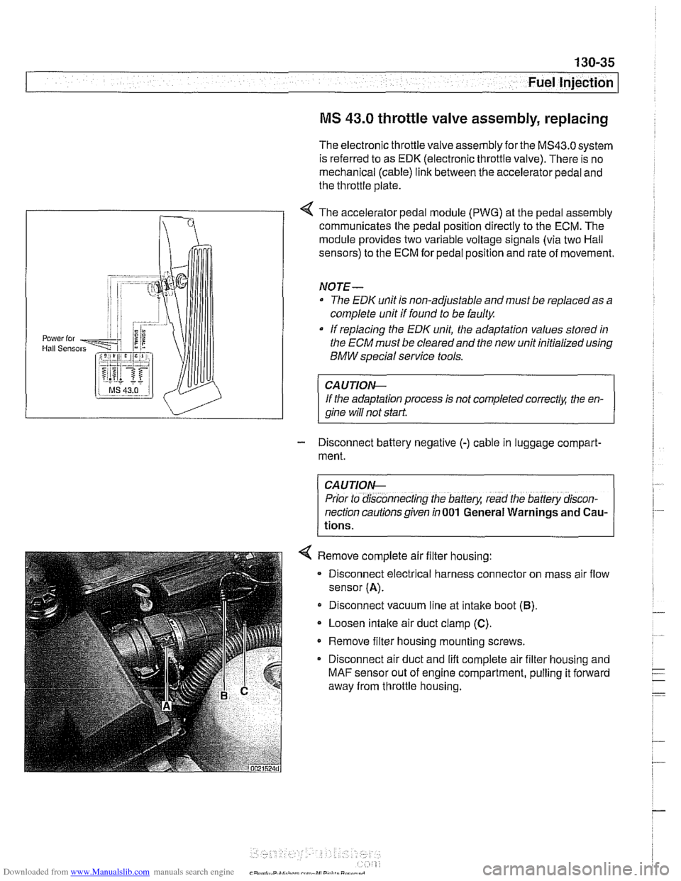
< The accelerator pedal module (PWG) at the pedal assembly
communicates the pedal position directly to the ECM. The
module provides two variable voltage signals (via two Hail
sensors) to the ECM for pedal position and rate of movement.
NOTE-
The EDK unit is non-adjustable and must be replaced as a
complete unit if found to be faulty
If replacing the
EDK unit, the adaptation values stored in
the
ECM must be cleared and the new unit initialized using
BMW special service tools.
CAUTIOIG
If the adaptation process is not completed correctk the en-
qine will not start
- Disconnect battery negative (-) cable in luggage compart-
ment.
CAUTION-
Prior to disconnecting the battery, read the battery discon-
nection cautions given in
001 General Warnings and Cau-
tions.
< Remove complete air filter housing:
- Disconnect electrical harness connector on mass air flow
sensor
(A).
Disconnect vacuum line at intake boot (6).
Loosen intaite air duct clamp (C).
Remove filter housing mounting screws.
Disconnect air duct and lift complete air filter housing and
MAF sensor out of engine compartment, pulling it forward
away from throttle housing.
Page 428 of 1002
Downloaded from www.Manualslib.com manuals search engine
130-38
Fuel Injection
Throttle cable, adjusting
(MS 42.0)
The throttle assembly on MS 42.0 cars uses a throttle cable.
The cable should be adjusted any time it is disconnected or
replaced. This procedure requires the factory scan tool or an
equivalent to read and adjust throttle angle. It is recommend-
ed the procedure be done by an authorized
BMW dealer ser-
vice department
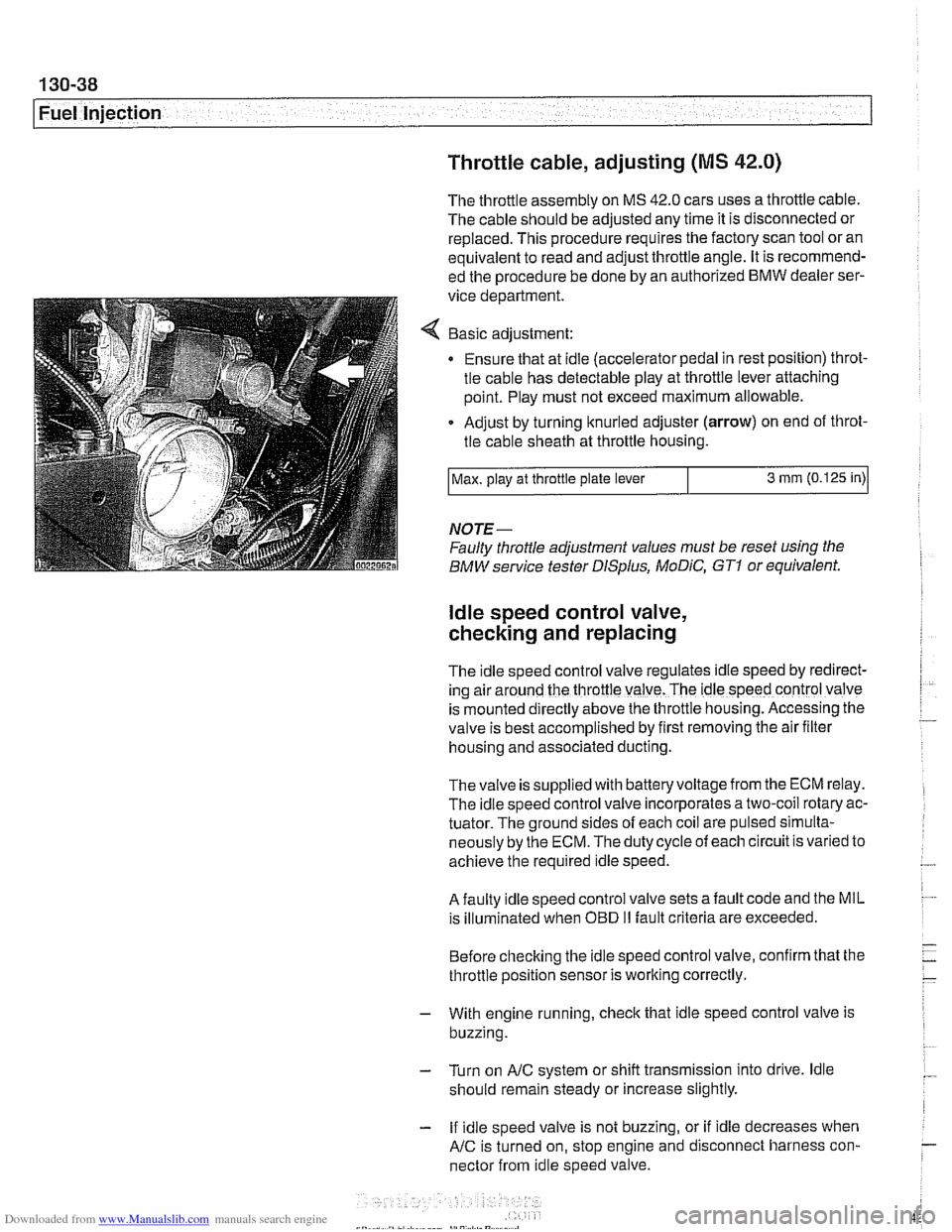
Basic adjustment:
Ensure that at idle (accelerator pedal in rest position) throt-
tle cable has detectable play at throttle lever attaching
point. Play must not exceed maximum allowable.
Adjust by turning knurled adjuster
(arrow) on end of throt-
tle cable sheath at throttle housing.
NOTE-
Faulty throttle adjustment values must be reset using the
BMW service tester
DISplus, MoDiC, GTI or equivalent.
Max.
play at throttle plate lever
ldle speed control valve,
checking and replacing
3 mm (0.125 in)
The Idle speed control valve regulates Idle speed by red~rect-
ing air around the throttle valve. The ldle speed control valve
is mounted
d~rectly above the throttle housing. Accessing the
valve is best accomplished by
flrst removing the air fllter
housing and associated ducting.
Thevalve is supplied with batteryvoltage from the ECM relay.
The idle speed control valve incorporates a two-coil rotary ac-
tuator. The ground sides of each coil are pulsed simulta-
neously by the ECM. The duty cycle of each circuit is varied to
achieve the required idle speed.
A faulty idle speed control valve sets a fault code and the MIL
is illuminated when
OED II fault criteria are exceeded.
Before checking the idle speed control valve, confirm that the
throttle position sensor is working correctly.
- With engine running, check that idle speed control valve is
buzzing.
- Turn on AIC system or shift transmission into drive. ldle
should remain steady or increase slightly.
- If idle speed valve is not buzzing, or if idle decreases when
AIC is turned on, stop engine and disconnect harness con-
nector from idle speed valve.
Page 433 of 1002
![BMW 540i 1997 E39 Workshop Manual Downloaded from www.Manualslib.com manuals search engine
130-43
Fuel Injection ]
I I I
12 llnput IFeedback signal, engine start /Starter
Table c. Siemens MS 42.0 and MS 43.0 ECM pin assignments BMW 540i 1997 E39 Workshop Manual Downloaded from www.Manualslib.com manuals search engine
130-43
Fuel Injection ]
I I I
12 llnput IFeedback signal, engine start /Starter
Table c. Siemens MS 42.0 and MS 43.0 ECM pin assignments](/img/1/2822/w960_2822-432.png)
Downloaded from www.Manualslib.com manuals search engine
130-43
Fuel Injection ]
I I I
12 llnput IFeedback signal, engine start /Starter
Table c. Siemens MS 42.0 and MS 43.0 ECM pin assignments (continued)
I I - I
13 Input /I Alternator (generator) Notes
Throttle
valve
Crankshaft position sensor
Throttle valve (MS
42.0)
Throttle valve
Pin
6
7
8
9
10
11
14
15
16
17
18
19
20
I 1- I
23 l~round I~round, intaite air temperature sensor /Intake air temperature sensor
Signal
Output
Input
Input
Input
I I I
Component/function
Not used
Throttle valve supply potentiometer
2
Signal, crankshaft position sensor
Signal,
pedal position sensor 2 (MS 42.0)
Signal, throttle position sensor 1
Not used
Ground
Ground
Input
Ground
Ground
Input
Ground Cranltshaft position sensor
21
24
25
26
27
28
29
30
I 1- I
33 1 input ISignal, cylinder 1 fuel injector /cylinder 1 fuel injector
Ground, throttle position sensor (MS
42.0)
Ground, exhaust camshaftsensor I
Signal, pedal position sensor 1 (MS 42.0)
Ground, mass air flow sensor
Ground, intake camshaft sensor
1
Signal, throttle potentiometer 1
Ground, throttle position sensor
22 loutput I~ignal, intake air temperature Ilntake air temperature sensor
I I - I
Throttle
valve (MS 42.0)
Camshaft position sensor I
Throttle valve (MS
42.0)
Hot film mass air flow sensor
Camshaft position sensor i
Throttle valve
Throttle valve
Ground
Output
Ground Input
Output
Ground
Output
Out~ut
Ground, crankshaft position sensor
Knoclt sensor
31
34
35
36
37
38
39
Signal, coolant temperature sensor
Ground, coolant temperature sensor
Signal,
oil pressure
Signal, engine
oil temperature sensor
Ground, engine oil temperature sensor
Signal, knock sensor
Signal, knock sensor
32 loutput ISignal, ltnock sensor l~nock sensor
40
41
Coolant temperature sensor
Coolant temperature sensor
Oil pressure switch
Oil temperature sensor
Oil temperature sensor
Knoclt sensor
I
Input
input
Input
Input
Input
Inout
Signal, knock sensor
Input
Input Signal, cylinder
2 fuel injector
Signal, cylinder
3 fuel injector
Signal, cylinder
4 fuel injector
Signal, cylinder
5 fuel injector
Signal, cylinder
6 fuel injector
Sianai, oil level sensor Cylinder
2 fuel
injector
Cylinder
3 fuel injector
Cylinder
4 fuel injector
Cylinder
5 fuel injector
Cylinder
6 fuel injector
Oil level sensor
-
Signal. VANOS inlet valve
Signal. VANOS outlet valve VANOS
inlet valve
VANOS outlet valve
Page 434 of 1002
Downloaded from www.Manualslib.com manuals search engine
Fuel Injection
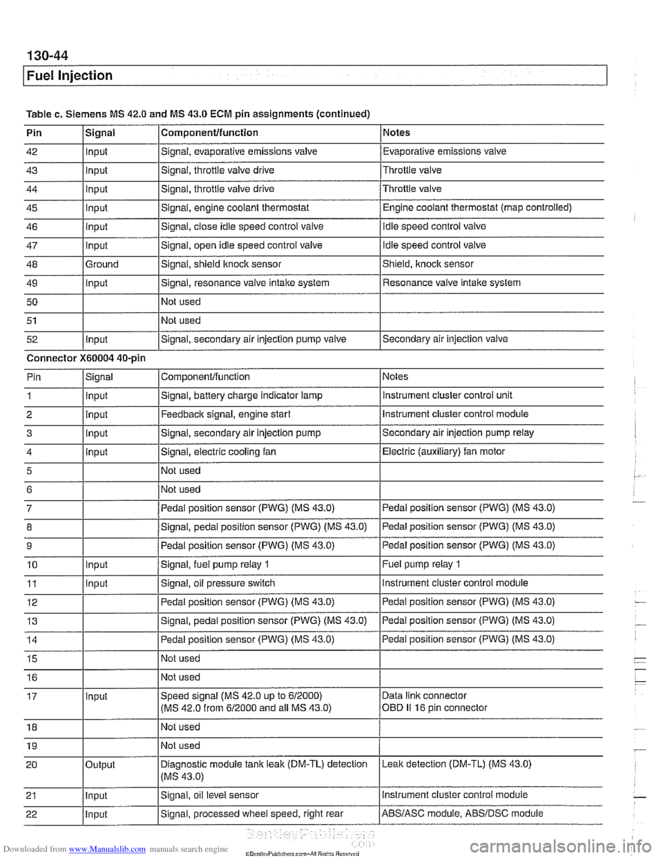
Table c. Siemens MS 42.0 and MS 43.0 ECM pin assignments (continued)
Pin
42
43
44
45
46
47
48
49 50
51
52 Componentlfunction
Signal, evaporative emissions valve
Signal, throttle
valve drive
Signal, throttle valve drive
Signal, engine coolant thermostat
Signal, close idle speed control valve
Signal, open idle speed control valve
Signal, shield
ltnock sensor
Signal, resonance valve
intake system
Not used
Not used
Signal, secondary air injection pump valve
Signal
Input
Input
Input
Input
input
Input
Ground
Input
Input
Notes
Evaporative emissions valve
Throttle valve
Throttle valve Engine coolant thermostat (map controlled)
idle speed control valve
Idle speed control valve
Shield,
knock sensor
Resonance valve intake system
Secondary air injection valve
Connector
X60004 40-pin Notes
instrument cluster control unit
Instrument cluster control module
Secondary air injection pump relay
Electric (auxiliary) fan motor
Pedal position sensor (PWG) (MS 43.0)
Pedal position sensor (PWG) (MS 43.0)
Pedal position sensor (PWG) (MS 43.0)
Fuel pump relay
1
Instrument cluster control module
ComponenVfunction
Signal, battery charge indicator lamp
Feedback signal, engine start
Signal, secondary air injection pump
Signal, electric cooling fan
Not used
Not used
Pedal position sensor (PWG) (MS 43.0)
Signal, pedal position sensor (PWG) (MS 43.0)
Pedal position sensor (PWG) (MS 43.0)
Signal,
fuel pump relay 1
Signal, oil pressure switch
Pin
1
2 3
4
5
6
7
8
9
10
11 Signal
Input
Input
input
input
Input
Input
Page 458 of 1002
Downloaded from www.Manualslib.com manuals search engine
130-68
Fuel Injection
0
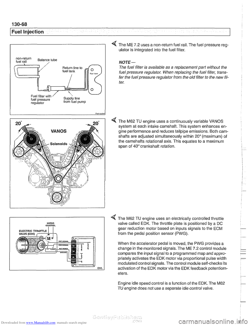
4 The ME 7.2 uses a non-return fuel rail. The fuel pressure reg-
ulator is integrated into the fuel filter.
I iY.,lii,in
4 The M62 TU engine uses a continuously variable VANOS
system at each intake camshaft. This system enhances en-
gine performance and reduces tailpipe emissions. Both cam-
shafts are adjusted simultaneously within
20" (maximum) of
the camshafts rotational axis. This equates to a maximum
span of
40°crankshaft rotation.
regulalor from luel pump
NOTE-
The fuel filter is available as a replacement part without the
fuel pressure regulator. When replacing the fuel filter, trans-
fer the fuel pressure regulator from the old
filter to the new fil-
ter.
Engine idle speed control is a function of the EDK. The M62
TU engine does not use a separate idle control valve.
Mmn CON,ROL
EML
< The M62 TU engine uses an electrically controlled throttle
valve called EDK. The throttle plate is positioned by a DC
gear reduction motor based on inputs signals to the ECM
from the pedal position sensor (PWG).
When the accelerator pedal is moved, the PWG provides a
change in the monitored signals. The ME
7.2 control module
compares the input signal to a programmed map and appro-
priately activates the EDK motor via proportional pulse width
modulated control signals. The control module self-checks its
activation of the EDK motor via the EDK feedbaclc
potentiom-
eters.
Page 632 of 1002
Downloaded from www.Manualslib.com manuals search engine
300-1 2
I Sus~ension, Steerincl and Brakes - General
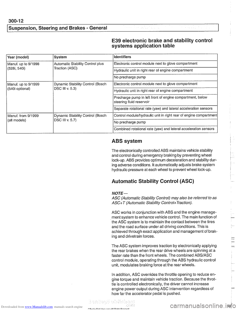
E39 electronic brake and stability control
systems application table
(528i, 54bi) Traction (ASC) I Hydraulic unit in right rear of engine compartment 1
Identifiers
Year (model)
I No precharge pump 1
Manuf. up to 911998 l~utomatic Stability Control plus I Electronic control module next to glove compartment
System
Precharge pump in
lefl front of engine compartment, below
steering fluid reservoir
Separate rotational rate (yaw) and lateral acceleration sensors
I I
Combined rotational rate (yaw) and lateral acceleration sensors
Electronic control
module next to glove compartment
Hydraulic unit in right rear of engine compartment
Manuf. up to 911999
(540i optional)
I I
ABS system
Dynamic Stability Control (Bosch
DSC
Ill v. 5.3)
The electronically controlled
ABS maintains vehicle stability
and control during emergency braking by preventing wheel
lock-up.
ABS provides optimum deceleration and stability dur-
ing adverse conditions. It automatically adjusts brake system
hydraulic pressure at each wheel to prevent wheel lock-up.
Control
moduleihydraulic unit
in right rear of engine compartment
No precharge pump
Manuf. from
911999
(all models)
Automatic Stability Control (ASC)
Dynamic Stability Control (Boscli
DSC Ill v. 5.7)
NOJE-
ASC (Automatic Stability Control) may also be referred to as
ASCiT (Automatic Stability ControkTraction).
ASC works in conjunction with ABS and the engine manage-
ment system to enhance vehicle control. The main function of
the
ASC system is to maintain the contact between the tires
and the road surface under all driving conditions. This is
achieved through exact application and management of brak-
ing and drivetrain forces.
The
ASC system improves traction by electronically applying
the rear brakes when the rear drive wheels are spinning at a
faster rate than the front wheels. The combined
ABSIASC
control module, operating through the ABS hydraulic control
unit, modulates braking force at the rear wheels.
In addition,
ASC overrides the throttle opening to reduce en-
gine torque and maintain vehicle traction. Because the throt-
tle is controlled electronically, the driver cannot increase
engine power output during
ASC intervention regardless of
how far the accelerator pedal is pushed.