mirror BMW 540I 1998 E39 Central Body Electronics ZKE Manual
[x] Cancel search | Manufacturer: BMW, Model Year: 1998, Model line: 540i, Model: BMW 540i 1998 E39Pages: 80, PDF Size: 4.14 MB
Page 1 of 80

Table of Contents
SubjectPage
Central Body Electronics (ZKE III) . . . . . . . . . . . . . . . . . . . . . . . . . . . . . .2
Objectives of the Module . . . . . . . . . . . . . . . . . . . . . . . . . . . . . . . . . . . . .2
Purpose of the System . . . . . . . . . . . . . . . . . . . . . . . . . . . . . . . . . . . . . . .3
System Components . . . . . . . . . . . . . . . . . . . . . . . . . . . . . . . . . . . . . . . .4
Power Distribution . . . . . . . . . . . . . . . . . . . . . . . . . . . . . . . . . . . . . . . . . .7
Windshield Wiping/Washing . . . . . . . . . . . . . . . . . . . . . . . . . . . . . . . . . . . 9
Headlight Washing . . . . . . . . . . . . . . . . . . . . . . . . . . . . . . . . . . . . . . . . . . 10
Rear Window Wiper/Washer . . . . . . . . . . . . . . . . . . . . . . . . . . . . . . . . . . 11
Rain Sensor . . . . . . . . . . . . . . . . . . . . . . . . . . . . . . . . . . . . . . . . . . . . . . 12
Central Locking. . . . . . . . . . . . . . . . . . . . . . . . . . . . . . . . . . . . . . . . . . . 17
Trunklid/Tailgate . . . . . . . . . . . . . . . . . . . . . . . . . . . . . . . . . . . . . . . . . . . 25
Remote (Keyless) Entry. . . . . . . . . . . . . . . . . . . . . . . . . . . . . . . . . . . . . . 26
Car Memory/Key Memory. . . . . . . . . . . . . . . . . . . . . . . . . . . . . . . . . . . . . 27
Anti-Theft (DWA) System . . . . . . . . . . . . . . . . . . . . . . . . . . . . . . . . . . . . . 33
Power Windows/Sunroof . . . . . . . . . . . . . . . . . . . . . . . . . . . . . . . . . . . . . 42
Interior Lighting. . . . . . . . . . . . . . . . . . . . . . . . . . . . . . . . . . . . . . . . . . . 51
Visual Entry Aid . . . . . . . . . . . . . . . . . . . . . . . . . . . . . . . . . . . . . . . . . . . . 55
Seat/Mirror/Steering Column Memory. . . . . . . . . . . . . . . . . . . . . . . . . . 58
Seat Functions . . . . . . . . . . . . . . . . . . . . . . . . . . . . . . . . . . . . . . . . . . . . 65
Steering Functions . . . . . . . . . . . . . . . . . . . . . . . . . . . . . . . . . . . . . . . . . . 66
General Functions. . . . . . . . . . . . . . . . . . . . . . . . . . . . . . . . . . . . . . . . . . .75
Consumer Cut Off/Overload Protection . . . . . . . . . . . . . . . . . . . . . . . . . . . 75
Sleep Mode . . . . . . . . . . . . . . . . . . . . . . . . . . . . . . . . . . . . . . . . . . . . . . . 76
Review Questions. . . . . . . . . . . . . . . . . . . . . . . . . . . . . . . . . . . . . . . . . . . 79
Page 2 of 80
2
Central Body Electronics ZKE III
Objectives of the Module
After completing this module, you will be able to:
• List the functions directly controlled by the GM III.
• Describe how the GM III recognizes the key position from the drivers door.
• Explain what “convenience” features are available from the FZV key.
• Describe how the Seat Module communicates a request for a stored memory position
with the mirror modules.
• List what circuits are controlled by Consumer Cut Off.
• Demonstrate how to Emergency disarm DWA.
• Describe the changes in the 2000 MY Key.
• Explain the electronic influence on power steering assist (Servotronic).
• Demonstrate how to open the sunroof (in the event of an electrical malfunction).
CENTRAL BODY ELECTRONICS (ZKE III)
Models: E38 - 740i(L) and 750iL
E39 - 525i, 528i, 530i, 540i and M5
E53 - X5 3.0i and X5 4.4i
Production Date: E38 1994 to Present
E39 1997 to Present
E53 1999 to Present
Manufacturer: Hella
Pin Connectors: White - 26 pin, Black 26 pin, Black 20 pin (large)
Page 3 of 80
3
Central Body Electronics ZKE III
Central Body Electronics (ZKE III)
Purpose of the System
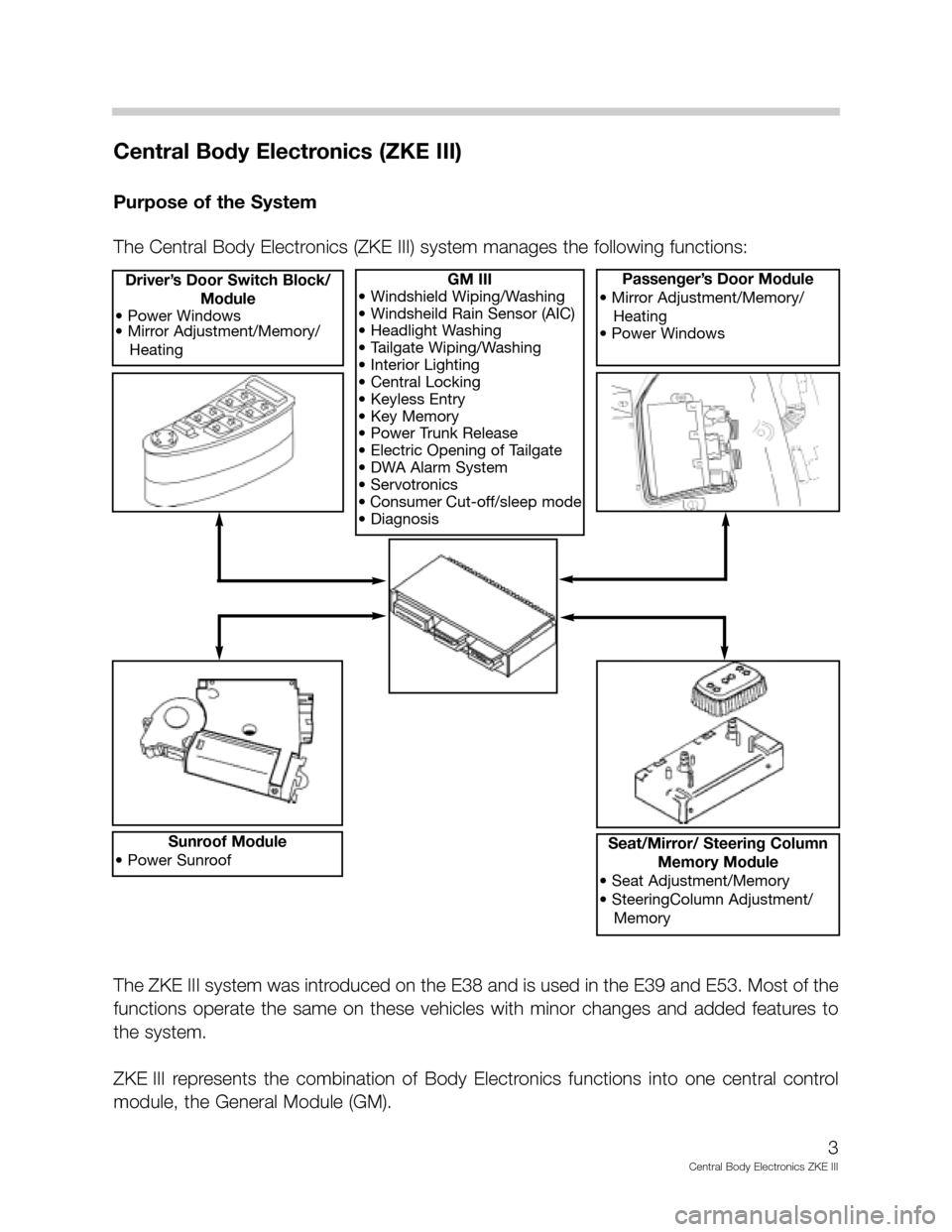
The Central Body Electronics (ZKE III) system manages the following functions:
GM III
• Windshield Wiping/Washing
• Windsheild Rain Sensor (AIC)
• Headlight Washing
• Tailgate Wiping/Washing
• Interior Lighting
• Central Locking
• Keyless Entry
• Key Memory
• Power Trunk Release
• Electric Opening of Tailgate
• DWA Alarm System
• Servotronics
• Consumer Cut-off/sleep mode
• DiagnosisDriver’s Door Switch Block/
Module
• Power Windows
• Mirror Adjustment/Memory/
HeatingPassenger’s Door Module
• Mirror Adjustment/Memory/
Heating
• Power Windows
Sunroof Module
• Power SunroofSeat/Mirror/ Steering Column
Memory Module
• Seat Adjustment/Memory
• SteeringColumn Adjustment/
Memory
The ZKE III system was introduced on the E38 and is used in the E39 and E53. Most of the
functions operate the same on these vehicles with minor changes and added features to
the system.
ZKE III represents the combination of Body Electronics functions into one central control
module, the General Module (GM).
Page 5 of 80
5
Central Body Electronics ZKE III
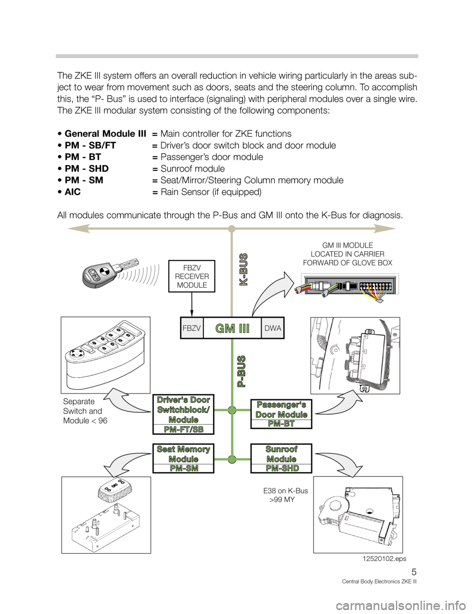
The ZKE III system offers an overall reduction in vehicle wiring particularly in the areas sub-
ject to wear from movement such as doors, seats and the steering column. To accomplish
this, the “P- Bus” is used to interface (signaling) with peripheral modules over a single wire.
The ZKE III modular system consisting of the following components:
• General Module III = Main controller for ZKE functions
• PM - SB/FT = Driver’s door switch block and door module
• PM - BT = Passenger’s door module
• PM - SHD =Sunroof module
•PM - SM =Seat/Mirror/Steering Column memory module
• AIC = Rain Sensor (if equipped)
All modules communicate through the P-Bus and GM III onto the K-Bus for diagnosis.
PM-FT/SB
PM-SMPM-BT
PM-SHD
P-BUS
K-BUS
Driver's Door
Switchblock/
ModuleDriver's Door
Switchblock/
Module
Seat Memory
ModuleSeat Memory
Module
Passenger's
Door ModulePassenger's
Door Module
Sunroof
ModuleSunroof
Module
GM IIIFBZVFBZVDWADWA
FBZV
RECEIVER
MODULE
GM III MODULE
LOCATED IN CARRIER
FORWARD OF GLOVE BOX
Separate
Switch and
Module < 96
E38 on K-Bus
>99 MY
12520102.eps
Page 6 of 80
6
Central Body Electronics ZKE III
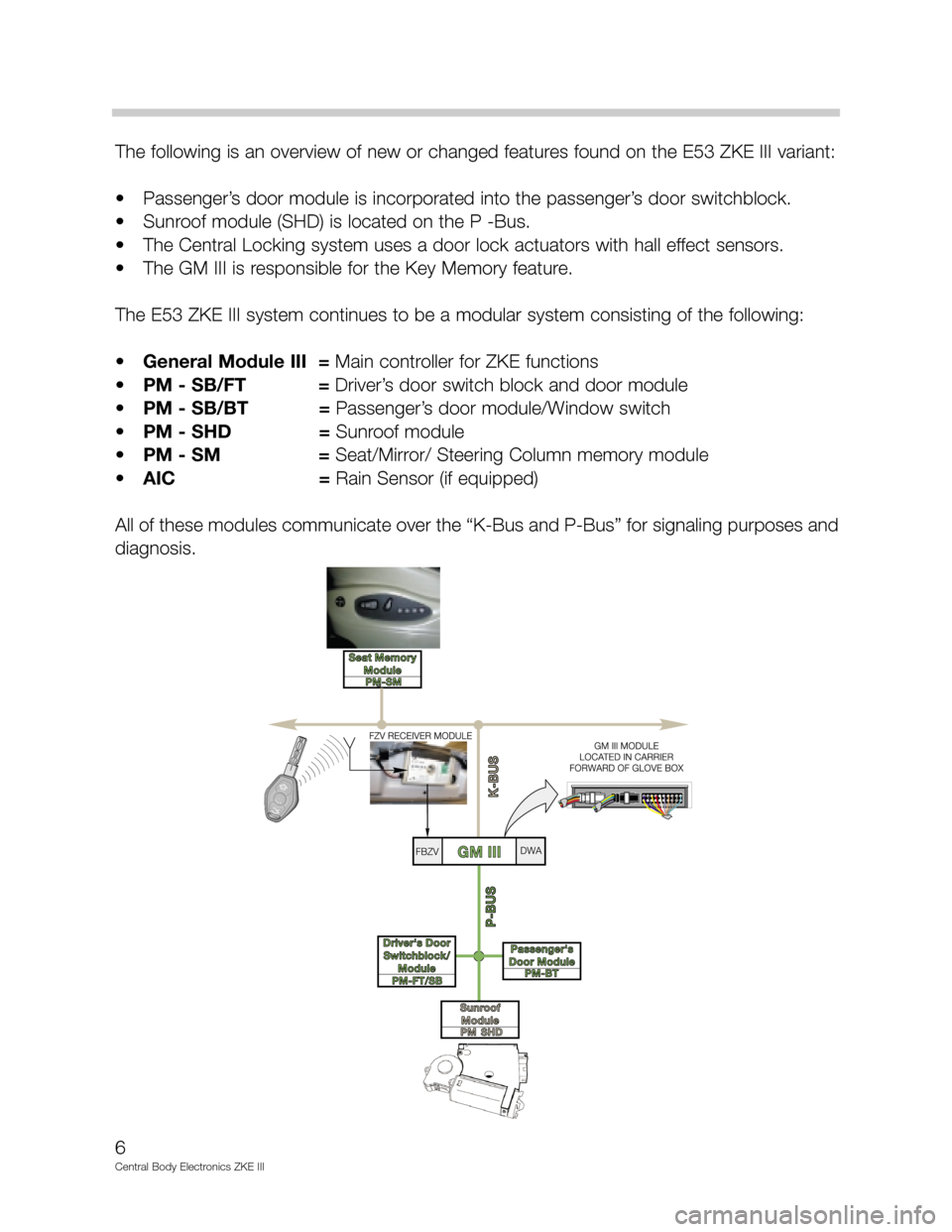
The following is an overview of new or changed features found on the E53 ZKE III variant:
• Passenger’s door module is incorporated into the passenger’s door switchblock.
• Sunroof module (SHD) is located on the P -Bus.
• The Central Locking system uses a door lock actuators with hall effect sensors.
• The GM III is responsible for the Key Memory feature.
The E53 ZKE III system continues to be a modular system consisting of the following:
•General Module III = Main controller for ZKE functions
•PM - SB/FT = Driver’s door switch block and door module
•PM - SB/BT =Passenger’s door module/Window switch
•PM - SHD =Sunroof module
•PM - SM =Seat/Mirror/ Steering Column memory module
•AIC = Rain Sensor (if equipped)
All of these modules communicate over the “K-Bus and P-Bus” for signaling purposes and
diagnosis.
Page 12 of 80
12
Central Body Electronics ZKE III
Rain Sensor (AIC - if equipped)
Purpose of the System
The Windshield Wiping System is also available with an optionally equipped Rain Sensor.
The Rain Sensor provides added driver convenience and enhances safety by automatical-
ly activating the intermittent function of the windshield wipers when water droplets are
detected on the windshield.
System Components
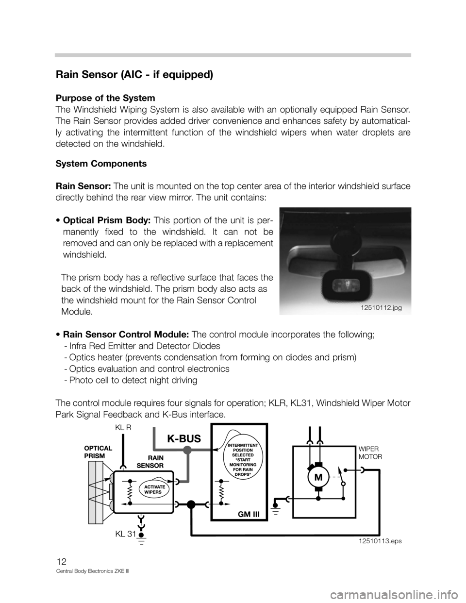
Rain Sensor: The unit is mounted on the top center area of the interior windshield surface
directly behind the rear view mirror. The unit contains:
• Optical Prism Body:This portion of the unit is per-
manently fixed to the windshield. It can not be
removed and can only be replaced with a replacement
windshield.
The prism body has a reflective surface that faces the
back of the windshield. The prism body also acts as
the windshield mount for the Rain Sensor Control
Module.
• Rain Sensor Control Module:The control module incorporates the following;
- Infra Red Emitter and Detector Diodes
- Optics heater (prevents condensation from forming on diodes and prism)
- Optics evaluation and control electronics
- Photo cell to detect night driving
The control module requires four signals for operation; KLR, KL31, Windshield Wiper Motor
Park Signal Feedback and K-Bus interface.
12510112.jpg
GM III
12510113.eps
Page 33 of 80
Anti-Theft (DWA) System
Purpose of the System
The DWA alarm system offers vehicle protection by monitoring the doors, hood, interior,
luggage compartment and vehicle tilting. When activated, DWA deters theft by sounding
an alarm siren for 30 seconds, flashing the low beam headlights (high beam on Xenon
equipped models) and four way flashers for 5 minutes.
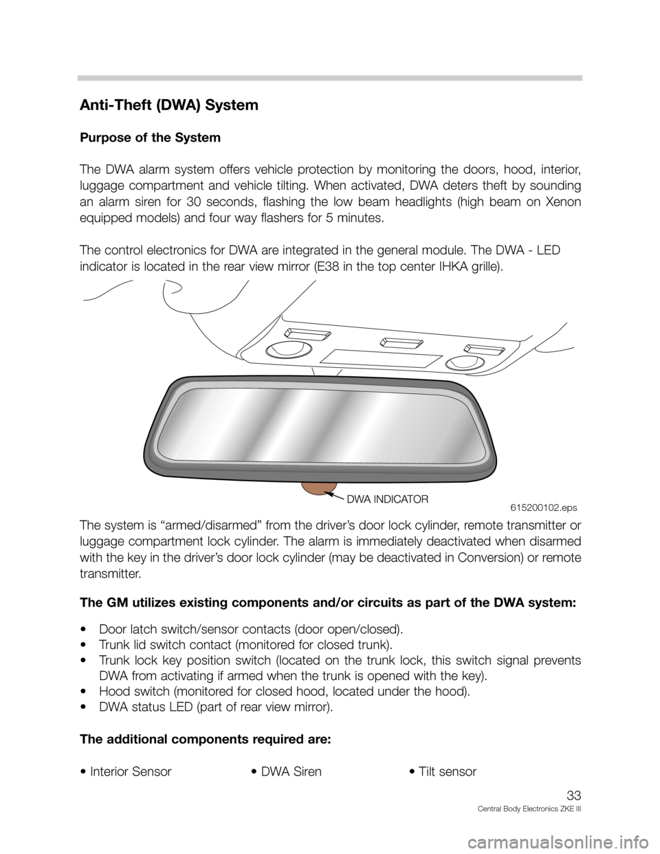
The control electronics for DWA are integrated in the general module. The DWA - LED
indicator is located in the rear view mirror (E38 in the top center IHKA grille).
The system is “armed/disarmed” from the driver’s door lock cylinder, remote transmitter or
luggage compartment lock cylinder. The alarm is immediately deactivated when disarmed
with the key in the driver’s door lock cylinder (may be deactivated in Conversion) or remote
transmitter.
The GM utilizes existing components and/or circuits as part of the DWA system:
• Door latch switch/sensor contacts (door open/closed).
• Trunk lid switch contact (monitored for closed trunk).
• Trunk lock key position switch (located on the trunk lock, this switch signal prevents
DWA from activating if armed when the trunk is opened with the key).
• Hood switch (monitored for closed hood, located under the hood).
• DWA status LED (part of rear view mirror).
The additional components required are:
• Interior Sensor • DWA Siren • Tilt sensor
33
Central Body Electronics ZKE III
615200102.eps
Page 55 of 80
Visual Entry Aid (E38/E53)
Purpose of the System
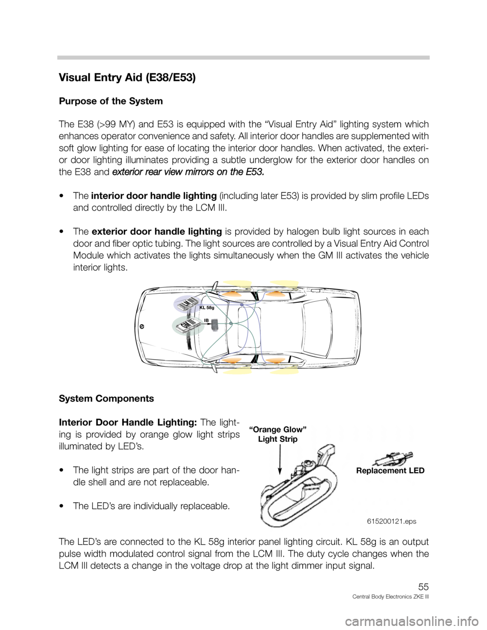
The E38 (>99 MY) and E53 is equipped with the “Visual Entry Aid” lighting system which
enhances operator convenience and safety. All interior door handles are supplemented with
soft glow lighting for ease of locating the interior door handles. When activated, the exteri-
or door lighting illuminates providing a subtle underglow for the exterior door handles on
the E38 and exterior rear view mirrors on the E53.
• The interior door handle lighting(including later E53) is provided by slim profile LEDs
and controlled directly by the LCM III.
• The exterior door handle lightingis provided by halogen bulb light sources in each
door and fiber optic tubing. The light sources are controlled by a Visual Entry Aid Control
Module which activates the lights simultaneously when the GM III activates the vehicle
interior lights.
System Components
Interior Door Handle Lighting: The light-
ing is provided by orange glow light strips
illuminated by LED’s.
• The light strips are part of the door han-
dle shell and are not replaceable.
• The LED’s are individually replaceable.
The LED’s are connected to the KL 58g interior panel lighting circuit. KL 58g is an output
pulse width modulated control signal from the LCM III. The duty cycle changes when the
LCM III detects a change in the voltage drop at the light dimmer input signal.
55
Central Body Electronics ZKE III
Replacement LED
“Orange Glow”
Light Strip
615200121.eps
Page 58 of 80
Seat/Mirror/Steering Column Memory
Purpose of the System
The front seats, outside rearview mirrors and steering column (if equipped) positions are
electrically adjustable. The “customized” adjustment positions can be memorized and
stored for three diferent users and recalled back to the individual positions (with the excep-
tion of the passenger seat - not in memory).
The basic features of seat/mirror/steering column operation, as well as the memory posi-
tions is integrated into the ZKE III system.
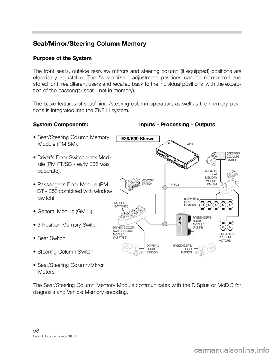
• Seat/Steering Column Memory
Module (PM SM).
• Driver’s Door Switchblock Mod-
ule (PM FT/SB - early E38 was
separate).
• Passenger’s Door Module (PM
BT - E53 combined with window
switch).
• General Module (GM III).
• 3 Position Memory Switch.
• Seat Switch.
• Steering Column Switch.
• Seat/Steering Column/Mirror
Motors.
The Seat/Steering Column Memory Module communicates with the DISplus or MoDiC for
diagnosis and Vehicle Memory encoding.
58
Central Body Electronics ZKE III
System Components: Inputs - Processing - Outputs
E38/E39 Shown
Page 59 of 80
59
Central Body Electronics ZKE III
System Components
- with Principle of Operation
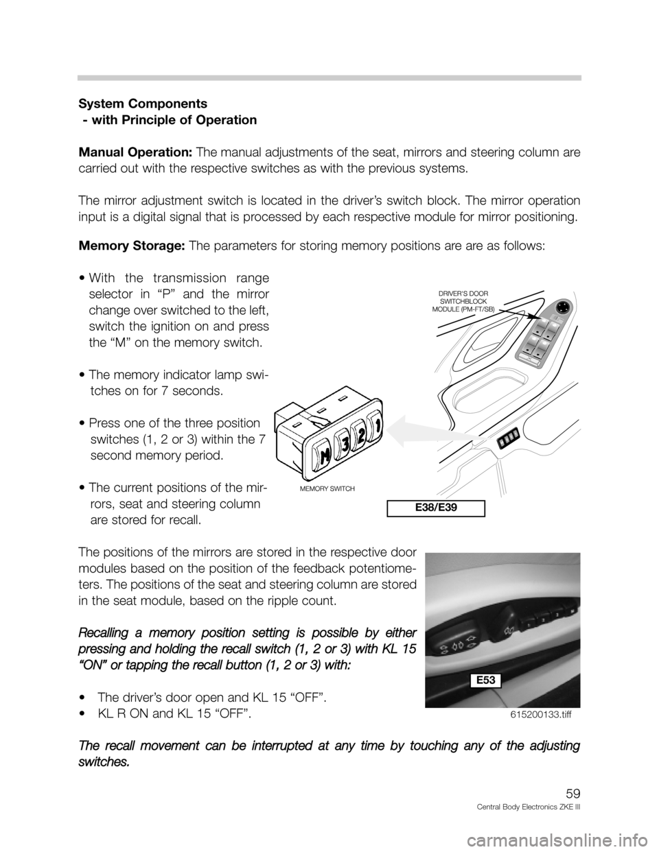
Manual Operation:The manual adjustments of the seat, mirrors and steering column are
carried out with the respective switches as with the previous systems.
The mirror adjustment switch is located in the driver’s switch block. The mirror operation
input is a digital signal that is processed by each respective module for mirror positioning.
Memory Storage: The parameters for storing memory positions are are as follows:
• With the transmission range
selector in “P” and the mirror
change over switched to the left,
switch the ignition on and press
the “M” on the memory switch.
• The memory indicator lamp swi-
tches on for 7 seconds.
• Press one of the three position
switches (1, 2 or 3) within the 7
second memory period.
• The current positions of the mir-
rors, seat and steering column
are stored for recall.
The positions of the mirrors are stored in the respective door
modules based on the position of the feedback potentiome-
ters. The positions of the seat and steering column are stored
in the seat module, based on the ripple count.
Recalling a memory position setting is possible by either
pressing and holding the recall switch (1, 2 or 3) with KL 15
“ON” or tapping the recall button (1, 2 or 3) with:
• The driver’s door open and KL 15 “OFF”.
• KL R ON and KL 15 “OFF”.
The recall movement can be interrupted at any time by touching any of the adjusting
switches.
E38/E39
E53
615200133.tiff