jack BMW 540i 1998 E39 Owners Manual
[x] Cancel search | Manufacturer: BMW, Model Year: 1998, Model line: 540i, Model: BMW 540i 1998 E39Pages: 1002
Page 861 of 1002
Downloaded from www.Manualslib.com manuals search engine
Exterior Trim, Bumpers
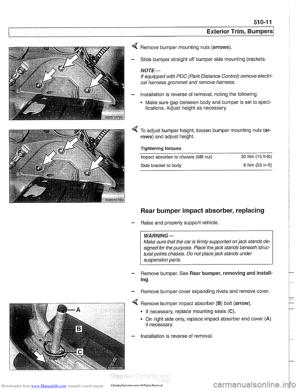
4 Remove bumper mounting nuts (arrows)
- Slide bumper straight off bumper side mounting brackets.
NOTE-
If equipped with PDC (Park Distance Control) remove electri-
cal harness grommet and remove harness.
- lnstallation is reverse of removal, noting the following:
Make sure gap between body and bumper is set to speci-
fications. Adjust height as necessary.
To adjust bumper height, loosen bumper mounting nuts (ar-
rows) and adjust height.
Tightening torques
Impact absorber to chassis (ME nut) 20 Nm (15 ft-lb)
Side bracket to body 6 Nm (53 in-it)
Rear bumper impact absorber, replacing
- Raise and properly support vehicle.
WARNING -
Make sure that the car is firmly supported on jack stands de-
signed for the purpose. Place the jack stands beneath
struc-
turalpoints chassis. Do not place jaclc stands under
suspension parts.
- Remove bumper. See Rear bumper, removing and install-
ing.
- Remove bumper cover expanding rivets and remove cover.
. - . . - . . ".-- < Remove b~mper mpact absorber (6) bot (arrow).
I If necessary, replace mounting seals (C).
- Installation is reverse of removal.
Page 862 of 1002
Downloaded from www.Manualslib.com manuals search engine
I Exterior Trim, Bumpers
Tightening torques Impact absorber to chassis
(M8 nut) 20 Nm (15 ft-lb)
Impact absorber to chassis
(M6 nut) 9 Nm (80 In-lb
Bumper bracket to impact absorber 45 Nm (32 ft-lb)
(MI0 bolt)
Front bumper height, adjusting
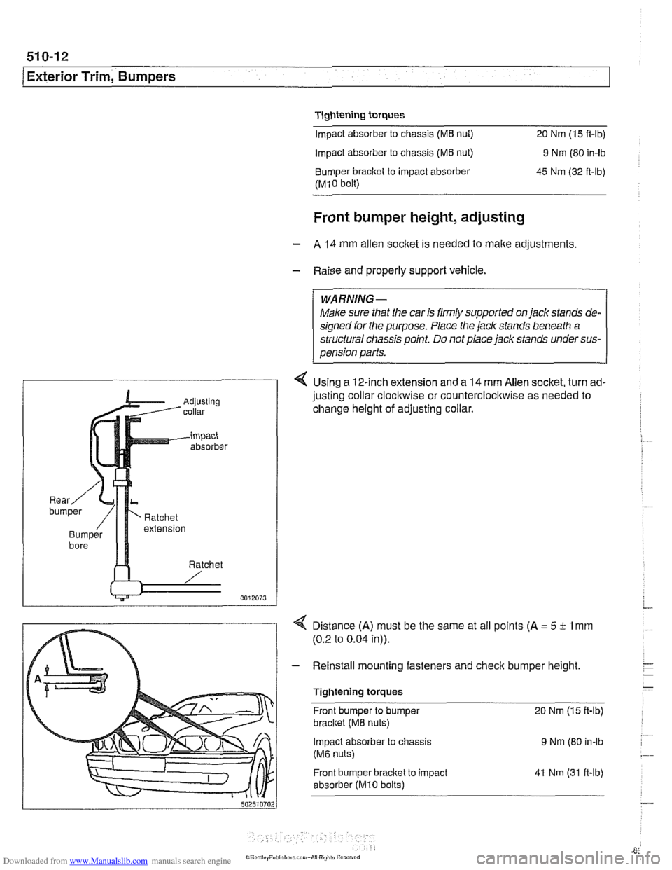
- A 14 mm allen socket is needed to make adjustments
- Raise and properly support vehicle.
WARNING-
Make sure that the car is firmly supported on jackstands de-
signed for the purpose. Place the jack stands beneath a
structural chassis point.
Do not place jack stands under sus-
pension parts.
4 Using a 12-inch extension and a 14 mm Allen socket, turn ad-
justing collar
clocl~wise or counterclocl~wise as needed to
change height of adjusting collar.
4 Distance (A) must be the same at all points (A = 5 i- 1 mm
(0.2 to 0.04 in)).
- Reinstall mounting fasteners and check bumper height
Tightening torques Front bumper to bumper
20 Nm (15 ft-lb)
bracltet (M8 nuts)
Impact absorber
to chassis 9 Nm (80 in-lb
(M6 nuts)
Front bumper bracket to impact
absorber
(MI0 bolts)
41 Nm (31 ft-lb)
Page 918 of 1002
Downloaded from www.Manualslib.com manuals search engine
51 5-24
l~entral Locking and Anti-Theft
ANTI-THEFT SYSTEM (DWA)
When the anti-then system (DWA) is armed, the doors, hood,
windows, trunk lid or tailgate are monitored against forcible
entry by switches and sensors. The vehicle is protected
against being jacked up or towed away by a tilt sensor.
The control electronics for DWA are integrated in the General
Module (GM). In addition to the control electronics, the sys-
tem includes the following components.
* DWA horn
DWA LED indicator
- Tilt sensor
- Monitoring switches and sensors
The system can be armed or disarmed from the driver's door
lock,
trunklid lock, tailgate lockorthe remote transmitter (FZV
Itey). When armed, the alarm horn
soundsfor30seconds and
the low beam headlights and turn signals flash for
5 minutes.
The electronic immobilizer (EWS) is also activated when
DWA is activated.
The alarm is switched off immediately if key is inserted in door
loclt or FZV key button is used.
DWA LED Status
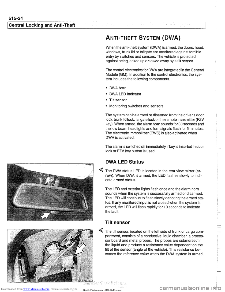
The DWA status LED is located in the rear view mirror (ar-
row). When DWA is armed, the LED flashes slowly to indi-
cate armed status.
The LED and exterior lights flash once and the alarm horn
sounds when the system is successfully armed ordisarmed.
The LED will continue to flash slowly denoting the armed sta-
tus. If any monitored input is not closed when the system is
armed, the LED will flash rapidly for
10 seconds to indicate
the fault.
Tilt sensor
-
4 The tilt sensor, located on the left side of trunlt or cargo com- -
partment, consists of a conductive liquid chamber, a proces-
sor board and metal probes. The probes are submersed in
the liquid and produce a resistance value dependent on the
tilt of the sensor (angle of the vehicle). This resistance be-
comes the reference value when the DWA system is armed.
.-
Page 919 of 1002
Downloaded from www.Manualslib.com manuals search engine
51 5-25
Central Lockina and ~nti-~heftl
1
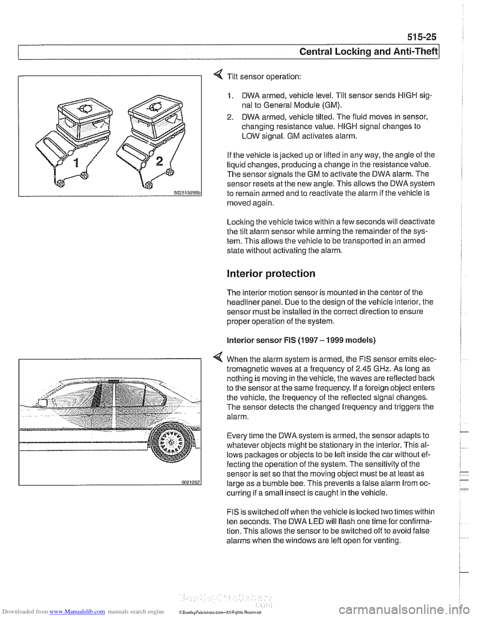
Tilt sensor operation:
1. DWA armed, vehicle level. Tilt sensor sends HlGH sig-
nal to General Module (GM).
2. DWA armed, vehicle tilted. The fluid moves in sensor,
changing resistance value.
HlGH signal changes to
LOW signal. GM activates alarm.
If the vehicle is jacked up or lifted in any way, the angle of the
liquid changes, producing a change in the resistance value.
The sensor signals the GM to activate the DWA alarm. The
sensor resets at the new angle.
This allows the DWA system
to remain armed and to reactivate the alarm if tlie vehicle is
moved again
Locking the vehicle twice within a few seconds will deactivate
the tilt alarm sensor while arming tlie remainder of the sys-
tem. This allows the vehicle to be transported in an armed
state without activating tlie alarm.
Interior protection
The interior motion sensor is mounted in the center of the
headliner panel. Due to the design of the vehicle interior, the
sensor must be installed in the correct direction to ensure
proper operation of the system.
lnterior sensor FIS (1997 - 1999 models)
4 When the alarm system is armed, the FIS sensor emits elec-
tromagnetic waves at
a frequency of 2.45 GHz. As long as
nothing is moving in the vehicle, the waves are reflected
baclc
to the sensor at the same frequency. If a foreign object enters
the vehicle, the frequency of the reflected signal changes.
The sensor detects the changed frequency and triggers the
alarm.
Every time the DWA system is armed, the sensor adapts to
whatever objects might be stationary in the interior. This al-
lows pacltages or objects to be left inside tlie car without ef-
fecting the operation of the system. The sensitivity of the
sensor is set so that the moving object must be at least as
large as a bumble bee. This prevents a false alarm from oc-
curring if a small insect is caught in the vehicle.
FIS is switched off when the vehicle is locked two times within
ten seconds. The DWA LED will flash one time for confirma-
tion. This allows the sensor to be switched off to avoid false
alarms when the windows are left open for venting.
Page 997 of 1002
Downloaded from www.Manualslib.com manuals search engine
INDEX 7
WARNING
Your common sense, good
judgement, and general alertness are
crucial to safe and successful service
work. Before
attempting any work on
your BMW, be sure to read 001
General Warnings and Cautions
and the copyright page at the front of
the manual. Review these warnings
and cautions each time you prepare
to
work on your BMW. Please also
read any warnings and
caulions that
accompany
/he procedures in the
manual.
Jack stands
010-16
Jump starting 010-19
Keys
515-1 1
Knock sensor
see Ignition system
Leak detection,
fuel tanlr
see Fuel tank, leak detection unit
Leather upholstery
see Maintenance, leather
upholstery and trim
LDP
(leak detection pump)
see Fuel
tanir, leal( detection unit
Level sender
see Fuel tank
see also Fuel pump
License
plate iight
630-1 1
Lifters see Cylinder head and vaivetrain
Lifting the car
010-5 Lights
bulb applications
630-2
control module (LCM) 630-3
foglights 630-8 headiighls 630-4
automatic headlight adjustment
(LWR)
630-7
vertical aim system 630-8 interior lights 630-12
bulb applications 630-13
side turn signal 630-9
taillight 630.10 trunk light bulb 630-14
turn signals, taillights 630-12
LOClCS see Central loci(ing
see also Door loclrs
Lubrication system
oil
level warning switch, replacing
119-20
oil pan, removinglinstalling
6-cylinder 119-10
V-E lower 119-13 V-8 upper 119-15
oil pressure
checiring 11
9-4
warning system, testing 119-5 warning switch, replacing 119-20
oil pressure
reliel valve
6-cylinder 119-26
V-8 11 9-27
oil pump, removinglinstalling
6-cylinder
119-22
V-8 1 19-4
troubieshooting 119-3
Luggage compartment
seeTrunk
MAF (mass air flow) sensor
see 130 under appropriate fuel
injection system Maintenance
accelerator linkage
020-14 air filter 020-14
automatic transmission 020-29
battery 020-22
body lubrication 020-31 body and interior 020-31
braire fluid 020-24
brake padlrotor wear 020-24
brake system 020-25 clutch fluid 020-26
cooling system 020-15
CV ioint boots 020-27
differential oil level 020-26
drive bells 020-16 engine comparlmenl 020-14
engine cooling system 020-16
engine oil 020-1 1 exhaust system 020-27
exterior washing 020-31
fluid and lubricant specifications 020-9
fuel lilter 020-27 fuel lanir and fuel lines 20-28
idle speed 020-19
inspection 020-5
interior care 020-31
lealher upholslery and trim 020-31
maintenance tables 020-6
manual transmission oil 020-30
microiilter 020-22 oxygen sensors 130-72, 180-8
parlcing brake 020-25
power steering fluid level 020-20
seat belts
020-32 service indicator 020-3
spark plugs 020-20
special cleaning 020-32 suspension, front 020-29
suspension, rear 020-29
tires 020-29
washing
020-32
waxing 020-32 windshield wiper blade 020-33
wheels, aligning 020-30
Malfunction indicator iight (MIL)
OED-2
Manifold, exhaust
see Exhaust system
Manifold,
intake
see Intake maniiold