Start BMW 540i 1998 E39 Workshop Manual
[x] Cancel search | Manufacturer: BMW, Model Year: 1998, Model line: 540i, Model: BMW 540i 1998 E39Pages: 1002
Page 828 of 1002
Downloaded from www.Manualslib.com manuals search engine
411-10
/Doors
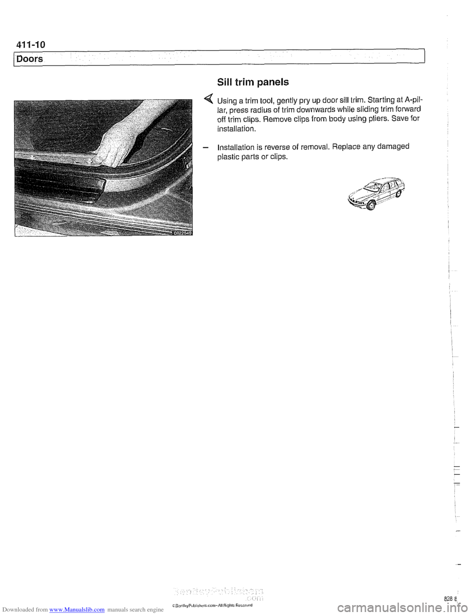
Sill trim panels
Using a trim tool, gently pry up door sill trim. Starting at A-pil-
lar, press radius of trim downwards while sliding trim forward
off trim clips. Remove clips from body using pliers. Save for
installation.
Installation is reverse of removal. Replace any damaged
plastic parts or clips.
Page 838 of 1002
Downloaded from www.Manualslib.com manuals search engine
.-
l~runk Lid, Tailgate
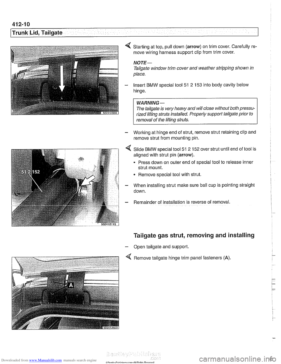
Starting at top, pull down (arrow) on trim cover. Carefully re-
move wiring harness support clip from trim cover.
NOTE-
Tailgate window trim cover and weather stripping shown in
place.
Insert BMW special tool 51 2
153 into body cavity below
hinge.
WARNING-
Tlie tailgate is ve!y heavy and will close without both pressu-
rized liftinq struts installed. Properly support
tailgafe prior to r
1 removal of the lifting struts.
- Working at hinge end of strut, remove strut retaining clip and
remove strut from mounting pin.
Slide BMW special tool 51 2 152 over strut until end of tool is
aligned with strut pin
(arrow).
Press down on outer end of special tool to release inner
strut mount.
Remove special tool with strut.
When installing strut make sure ball cup is pointing straight
down.
Rema~nder of installation 1s reverse of removal.
Tailgate gas strut, removing and installing
- Open tailgate and support.
Remove tailgate hinge trim panel fasteners
(A).
Page 839 of 1002
Downloaded from www.Manualslib.com manuals search engine
Trunk Lid, Tailgate
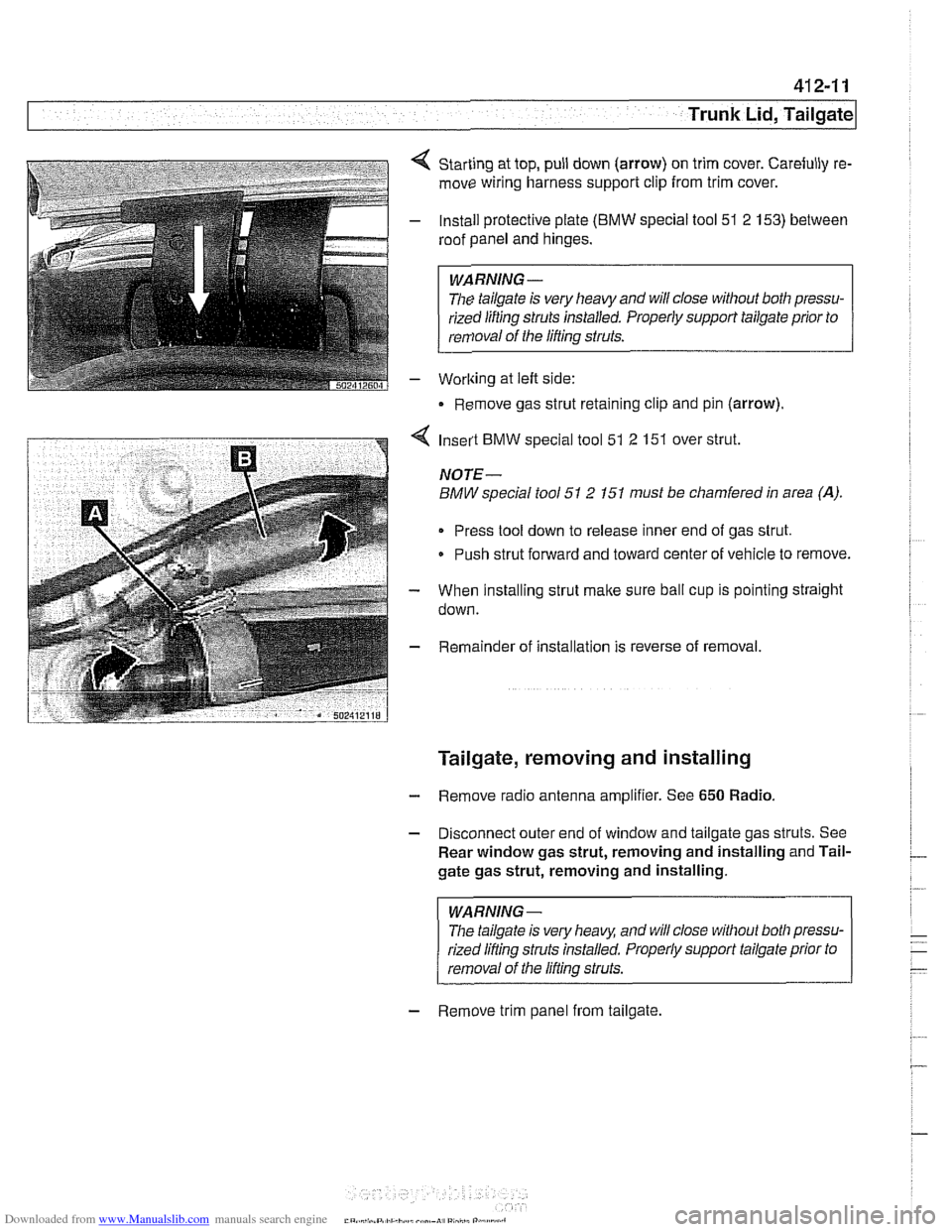
Starting at top, pull down (arrow) on trim cover. Carefully re-
move wiring harness support clip from trim cover.
Install protective plate
(BMW special tool 51 2 153) between
roof panel and hinges.
WARNING -
The tailgate is very heavy and will close without both pressu-
rized lifting
struts installed. Properly support tailgate prior to
removal of the lifting struts.
Worlting at left side:
Remove gas strut retaining clip and pin (arrow).
4 Insert BMW special tool 51 2 151 over strut.
NOTE-
BMW special tool 51 2 151 must be chamfered in area (A).
Press tool down to release inner end of gas strut.
Push strut forward and toward center of vehicle to remove.
- When installing strut make sure ball cup is pointing straight
down.
- Remainder of installation is reverse of removal.
Tailgate, removing and installing
- Remove radio antenna amplifier. See 650 Radio.
- Disconnect outer end of window and tailgate gas struts. See
Rear window gas strut, removing and installing and Tail-
gate gas strut, removing and installing.
WARNING-
The tailgate is very heaq and will close without both pressu-
rized lifling struts installed. Properly support tailgate prior to
removal of the lifling struts.
- Remove trim panel from tailgate.
Page 874 of 1002
Downloaded from www.Manualslib.com manuals search engine
Door Windows
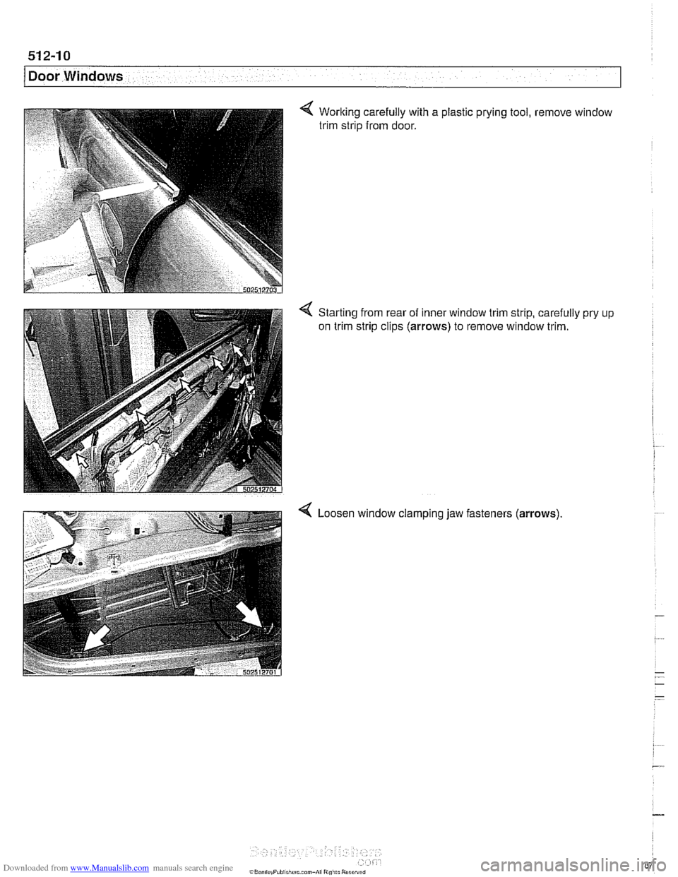
Worlting carefully with a plastic prying tool, remove window
trim strip from door.
Starting from rear of inner window trim strip, carefully
on trim strip clips
(arrows) to remove window trim.
< Loosen 1 clamping jaw ' fasteners (arrows)
Page 881 of 1002
Downloaded from www.Manualslib.com manuals search engine
513-3
Interior ~rirnl
The console between the two front seats starts behind the shifler housing. It houses the parking brake handle, optional
telephone and oddments storage tray. The rear portion of the
console houses the ashtray and covers the emergency brake
cable ends.
NOTE-
The accompanying photos illustrate a model with automatic
transmission. Manual transmission models are similar.
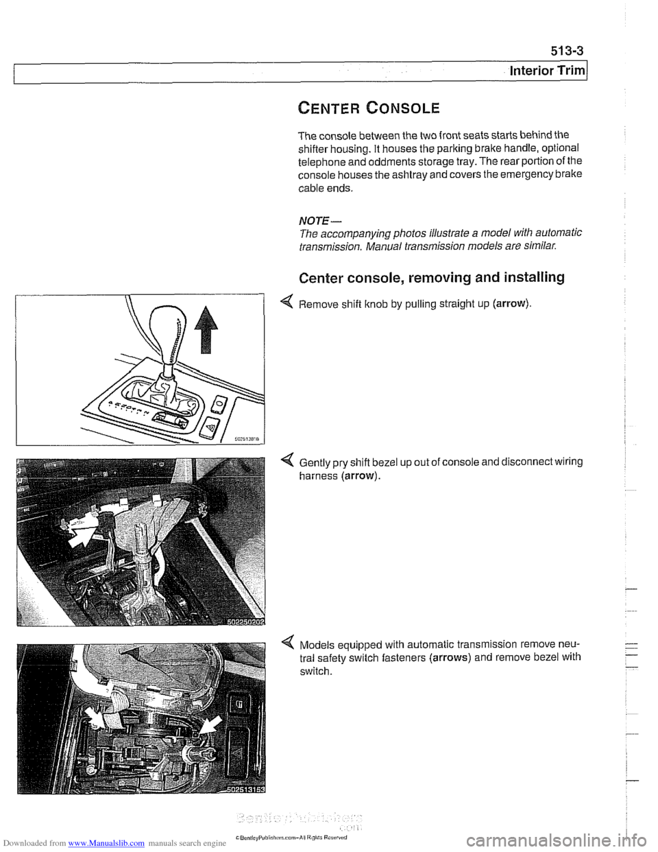
Center console, removing and installing
4 Remove shift knob by pulling straight up (arrow).
Gently pry shift bezel
harness (arrow). up
out of console and disconnect wiring
Models equipped with automatic transmission remove neu-
tral safety switch fasteners (arrows) and remove bezel with
switch.
Page 885 of 1002
Downloaded from www.Manualslib.com manuals search engine
Interior Trim
The E39 dashboard assembly includes the instrument clus-
ter, passenger side
airbag, glove compartment, fuse and re-
lay panel, radio. IHKA control panel oron-board monitor (if
equipped with GPS). The dash is made up of an upper and
lower sections. The lower section must be remove before the
upper section can be removed.
Dashboard removal is a complex operation. Read the proce-
dures through before starting work.
Lower dash panel assembly, removing and
installing
- Disconnect negative (-) cable from battery and cover termi-
nal with
insulating material.
--7
CAUTION-
Prior to disconnecting the battery, read the battery discon-
nectioncautionsgiven atthe irontin001 General Warnings
and Cautions.
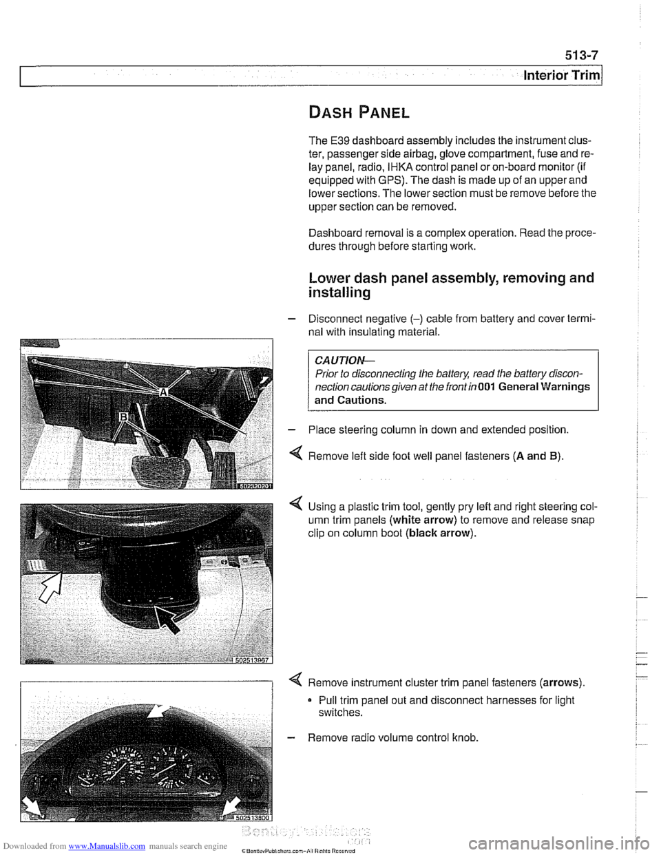
- Place steering column in down and extended position.
4 Remove left side foot well panel fasteners (A and B).
< Using a plastic trim tool, gently pry left and right steering col-
umn trim panels (white arrow) to remove and release snap
clip on column boot
(black arrow).
I 1 < Remove instrument cluster trim panel fasteners (arrows).
Pull trim panel out and disconnect harnesses for light
switches.
- Remove radio volume control knob.
Page 896 of 1002
Downloaded from www.Manualslib.com manuals search engine
51 5-2
/Central Locking and Anti-Theft
This section covers repair information for door, trunk and car-
go compartment locks, central locking, electronic
immob~liza-
tion (EWS) and anti-theft alarm (DWA).
€39 cars are equipped with sophisticated self-diagnostic elec-
trical systems. When experiencing malfunctions relating to
central locking. EWS or anti-theft systems, start the diagnosis
process using the
BMW service tester DIS, GT 1, MoDiC or
equivalent scan tool. An advanced diagnostic scan tool can
usually pinpoint electrical faults quickly and safely.
Additional electrical information can be found in:
610 Electrical Component Locations
ELE Electrical Wiring Diagrams
Central locking in E39 vehicles controls the door
locks, trunk
or tailgate lock and fuel filler flap lock. The control module for
the Central Body Electronics system (ZKE
Ill), lknown as the
General Module (GM
Ill), controls central locking.
ZKE
Ill manages the following central locking related func-
tions:
Central locking
* Keyless entry
Key memory
Power trunk release
Electric opening of tailgate
DWA alarm system
Diagnosis
General Module
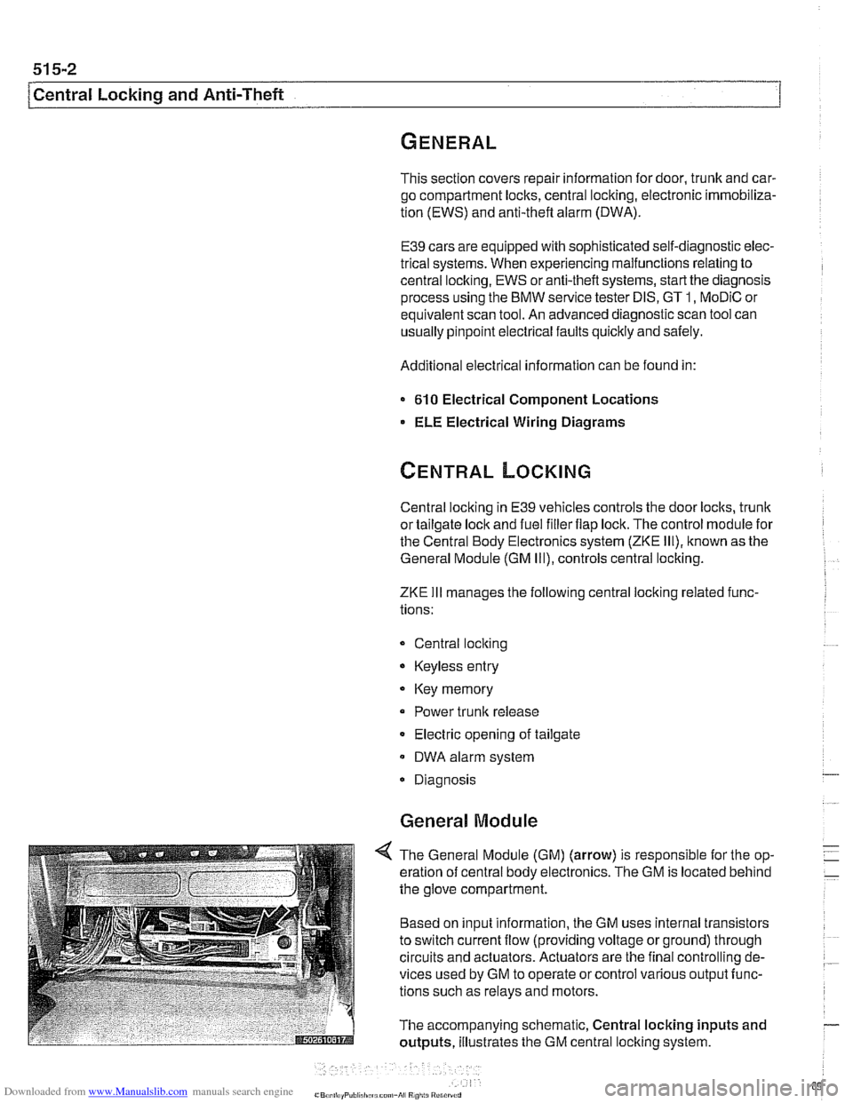
4 The General Module (GM) (arrow) is responsible for the op-
eration of central body electronics. The GM is located behind
the glove compartment.
Based on input information, the GM uses internal transistors
to switch current flow (providing voltage or ground) through
circuits and actuators. Actuators are the final controlling de-
vices used by GM to operate or control various output func-
tions such as relays and motors.
The accompanying schematic, Central locking inputs and
outputs, illustrates the GM central locking system.
Page 900 of 1002
Downloaded from www.Manualslib.com manuals search engine
51 5-6
(Central Locking and Anti-Theft
Each rear door is equipped with the child lock-out lever, pre-
venting the door from being opened from the inside regard-
less of loclc button position.
Starting with models produced afler
911997, the General
Module and electronic immobilizer (EWS) interface via the
K-
Bus to monitor double lock status and to initiate double loclc
override. This feature allows the doors to be opened from the
inside if a key accepted by EWS is switched on in the ignition.
See Single lock and double lock function.
The door loclc buttons are mechanically uncoupled from the
actuators when locked. The remote keyless entry system
(FZV) is standard equipment. This allows for elimination of
the passengers side door
loclt cylinder.
Another function of the locking system is the
sofl close trunk
(SCA) system, where applicable.
Single lock and double lock function
(2000 and later models)
On models produced after
911999, each door lock actuator in-
corporates two motors:
Single lock motor controls the mechanical loclc mechanism
when the central lock switch is pressed to single loclc the
vehicle. The loclc mechanism is fully locked at this point but
can stil. be openeo from
the interor by pulng the appropri-
are interior door nandle lwce or by pressing rhe central
lock switch again. When single
lock'function is activated,
the fuel filler flap actuator is not locked.
Double lock motor, also known as central arrest, is activat-
ed only when the vehicle is locked from the outside at the
driver's door lock with a key or when the GM receives a
lock request from the remote entry (FZV) system. In this
case the double lock motor is activated simultaneously
with the single lock motor. The function of the double loclc
motor is to mechanically offset an internal rod in the loclc
actuator, disabling it from unlocking the vehicle from the in-
terior. This prevents the doors from being unloclted by any
means except from an unlock request at the driver's door
or via the FZV remote key.
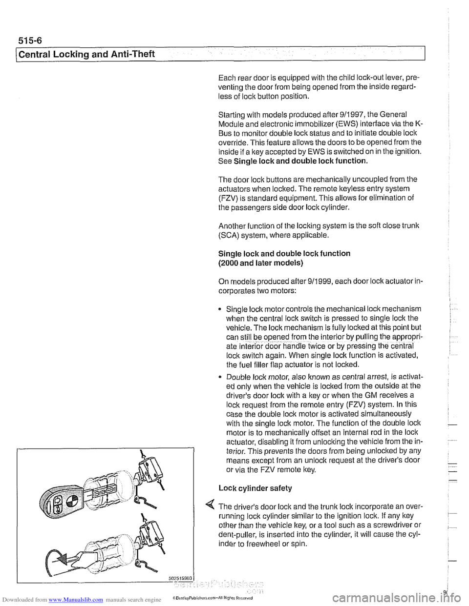
Lock cylinder safety
4 The driver's door loclc and the trunk loclc incorporate an over-
running loclc cylinder similar to the ignition lock. If any key
other than the vehicle key, or a tool such as a screwdriver or
dent-puller, is inserted into the cylinder, it will cause the cyl-
inder to freewheel or spin.
Page 904 of 1002
Downloaded from www.Manualslib.com manuals search engine
1 Central Locking and Anti-Theft
NOJE-
A single unlock request from the driver's door with the FZV
key unlocks the driver's door only.
A second unlock request
unlocls the remaining doors and trunk. This feature can be
modified for individual users with the Key Memory capabil-
ities to activate all lock actuators simultaneously See Car
Memory
/ Key Memory later in this section.
Starting with 2000 models, the battery in the FZV ignition
Icey is recharged by the ignition switch ring antenna while
the ley is in the ignition switch.
Transmitter self-test (models to
1999)
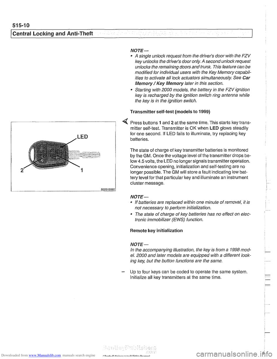
Press buttons 1 and 2 at the same time. This starts ltey trans-
/ mitter self-test. Transmitter is OK when LED glows steadily
te{le"el for that particular key and illuminate an instrument
cluster message.
-- 502515092 J
NO JE-
If batteries are replaced within one minute of removal, it is
not necessary to
periorm initialization.
Tlie state of charge of key batteries has no effect on elec-
tronic immobilizer (EWS) function.
2
Remote key initialization
for one second. If LED fails to illuminate, try replacing ltey~
batteries.
The state of charge of key transmitter batteries is monitored
by the
GM. Once the voltage level of the transmitter drops be-
low
4.5volts, the LED no longersignals transmitteroperation.
Convenience opening, initialization and self-testing are no
lonaer ~ossible. The GM will store a fault indicatina low bat-
NOJE-
In the accompanying illustration, the key is from a 1998 mod-
el. 2000 and later models are equipped with a different look-
ing
/
Initialize all key transmitters at the same time.
Page 907 of 1002
Downloaded from www.Manualslib.com manuals search engine
- -
Central Locking and ~nti-~hefil
Key Memory
Whenever one of the FZV keys is used to lock or unlock the
car, the user is identified by the GM. A maximum of four
keys
can be programmed with the Key Memoryfeature. The use of
the personalized key then triggers Car Memory functions
such as heating
I AIC (IHKA) settings or memory seat position
adjustment.
Most programming of Key Memory requires the use of
BMW
scan tools (DISplus, GT1 or MoDiC). However, features such
as
IHKA blower speed and temperature store automatically
without the use of scan tools.
Available Key Memory functions vary based on vehicle equip-
ment. The functions that can be set include:
Automatic locking after start off (vehicle speed)
Selective locking
Heating
1 AJC blower speed, heated or cooled air distribu-
tion, automatic blower setting
Trunk lid soft close (SCA)
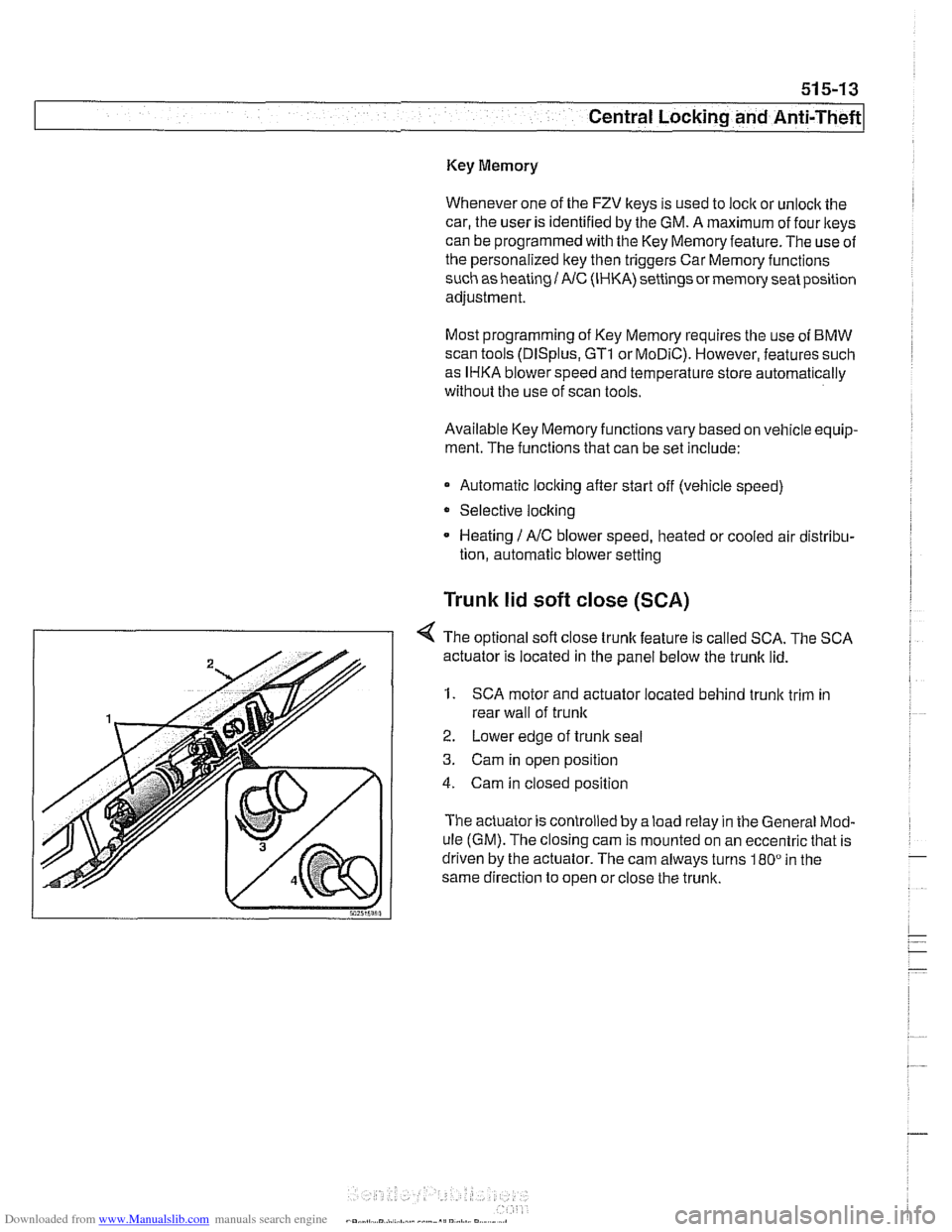
< The optional sofl close trunk feature is called SCA. The SCA
actuator is located in the panel below the trunk lid.
1. SCA motor and actuator located behind trunk trim in
rear wall of
trunlc
2. Lower edge of trunlc seal
3. Cam in open position
4. Cam in closed position
The actuator is controlled by a load relay in the General Mod-
ule (GM). The closing cam is mounted on an eccentric that is
driven by the actuator. The cam always turns
180" in the
same direction to open or close the trunk.