ECO mode BMW 540i 1998 E39 User Guide
[x] Cancel search | Manufacturer: BMW, Model Year: 1998, Model line: 540i, Model: BMW 540i 1998 E39Pages: 1002
Page 55 of 1002
Downloaded from www.Manualslib.com manuals search engine
Maintenance
- To remove battery corrosion:
Disconnect battery cables. Disconnect negative (-)cable
first.
* Remove battery from trunk
Clean terminal posts and cable clamps with a wire brush.
Clean main chassis ground terminal next to battery.
Corrosion can be washed away with a
baking soda and
water solution that will neutralize acid.
Reinstall battery and reconnect cable clamps, positive
(+)
cable first.
Lightly coat outside of terminals, hold down screws, and
clamps with petroleum jelly, grease, or a commercial
battery terminal corrosion inhibitor.
WARNING
-
Battery acid is extremely dangerous. Take care to keep it
from contacting eyes, skin, or clothing. Wear eye protection.
Extinguish all
smolihg materials and do not work near any
oaen flames.
CAUTION-
Prior to disconnecting the batteg read the battery discon-
nection cautions given in
001 General Cautions and
Warnings.
NOTE-
The original equipment battery in E39 models is mainte-
nance free. The original electrolyte will normally last the
entire service life of the battery under moderate climate con-
ditions.
Battery electrolyte should be maintained at the correct level
just above the battery plates and theirseparators. The correct
level is approximately
5 mm ('14 in.) above the top of battery
plates or to the top of the indicator
marks (if applicable). The
battery plates and the indicator marks can be seen once the
fillercaps are removed.
if theelectrolyte level is low, replenish
it by adding distilled water only.
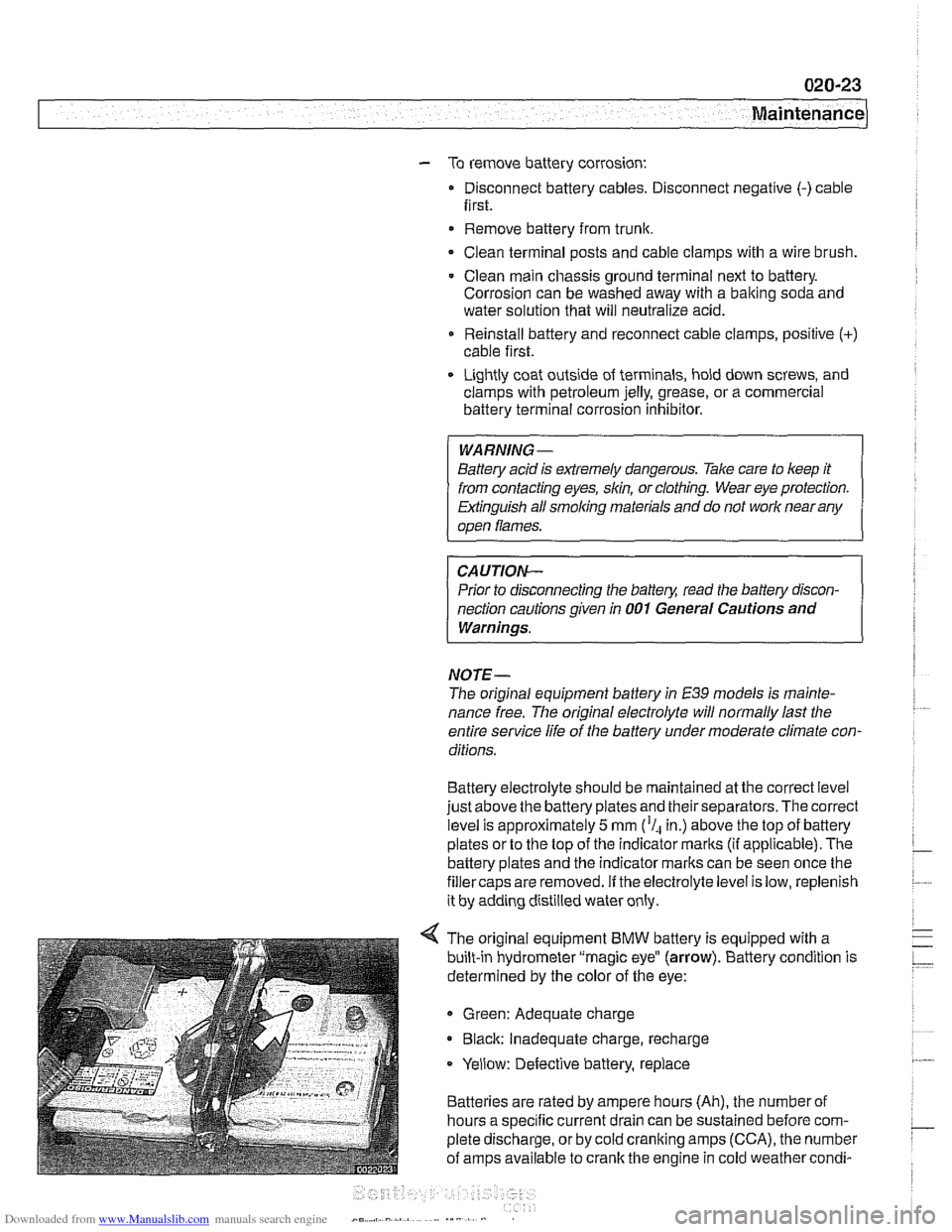
4 The original equipment BMW battery is equipped with a
built-in hydrometer "magic eye"
(arrow). Battery condition is
determined by the color of the eye:
Green: Adequate charge
* Black: Inadequate charge, recharge
Yellow: Defective battery, replace
Batteries are rated by ampere hours (Ah), the number of
hours a specific current drain can be sustained before com-
plete discharge, or by cold cranking amps (CCA), the number
of amps available to crank the engine in cold weather
condi-
Page 61 of 1002
Downloaded from www.Manualslib.com manuals search engine
Maintenance
Suspension, front, inspecting
Inspection of the front suspension and steering includes a
check of all moving parts
forwear and excessive play. Inspect
ball joint and tie-rod rubber seals and boots for cracks
ortears
that could allow the entry of dirt, water, and other
contaminants. See
310 Front Suspension.
Suspension, rear, inspecting
Differential and rear drive axle service consists of checking
and changing the gear oil, inspecting for leaks, and checking
the drive axle
CV joint boots for damage.
The areas where
lealts are most likely to occurare around the
drive shaft and drive axle mounting flanges. For more infor-
mation on identifying oil leaks and theircauses, see
330 Rear
Suspension and
331 Final Drive.
Tires, checking inflation pressure
Correct tire pressures are important to handling and stability,
fuel economy, and tire wear. Tire pressures change with tem-
perature. Pressures should be
checked oRen during season-
al temperature changes. Correct inflation pressures can be
found on the driver's door pillar and in the owner's manual.
Note that tire pressures should be higher when the car is
more heavily loaded.
WARNING-
Do not inflate any tire to a pressure higher than the tire's max-
imum inflation pressure listedon the sidewall. Use care when
adding air to warm tires. Warm tire pressures can increase as
much as
4 psi (0.3 bar) over their coldpressures.
Tires, rotating
BMW does not recommend tire rotation. Due to the car's sus-
pension design, the front tires begin to wear first at the outer
shoulder and the reartires begin to wearfirst at the middle of
the tread or inner shoulder. Rotating the tires may adversely
affect road handling and tire grip.
Transmission service, automatic
The automatic transmissions installed in E39 models are
filled with special automatic transmission fluid. The transmis-
sion lubricant type can be found on the "type-plate" on the
side of the transmission. The recommended lubricants are
listed earlier in this repair group. See Fluids and lubricants.
If in doubt, consult an authorized BMW dealer for alternate
Page 62 of 1002
Downloaded from www.Manualslib.com manuals search engine
020-30
Maintenance
fluid use and the most-up-to-date information regarding
transmission operating fluids.
The automatic transmission is not equipped with a dipstick.
Therefore, checking the ATF level is an involved procedure
which includes measuring and maintaining a specified ATF
temperature during the checking procedure.
For more complete
ATF service information, including
checking
ATF level and ATF filter replacement procedures,
see
240 Automatic Transmission.
Transmission service, manual
Manual transmission service consists of inspecting for leaks
and checking the fluid. Evidence of transmission leaks is
like-
ly to be seen around the driveshaft mounting flange and at the
bottom of the bellhousing.
NOTE-
For more information on identifying oil
leaks and their
causes, see 230 Manual Transmission and210 Clutch.
Transmission fluid, checking and filling
(manual transmission)
Tne manual transmss'on inslalleo 'n rne E39 models s f;lled
with a special liierime iluid (ivlTF-LT-I). oi. ordinarily
does
not need to be changed.
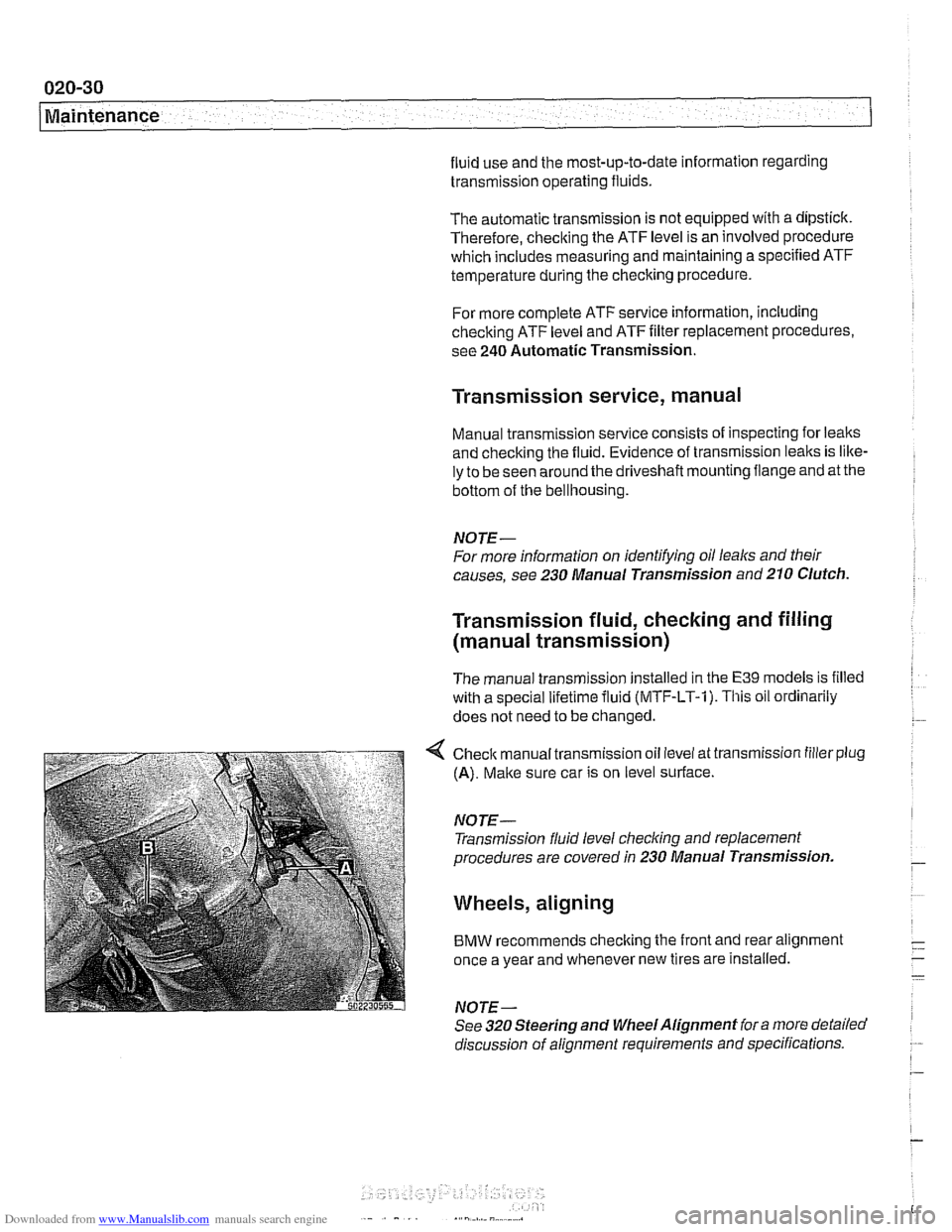
< Check manual transmission oil level at transmission filler plug
(A). Make sure car is on level surface.
NOTE- Transmission fluid level
checking and replacement
procedures are covered in 230 Manual Transmission.
Wheels, aligning
BMW recommends checking the front and rear alignment
once a year and whenever new tires are installed.
NOTE-
See 320 Steering and Wheel Alignment for a more detailed
discussion of alignment requirements and specifications.
Page 271 of 1002
Downloaded from www.Manualslib.com manuals search engine
Camshaft Timing Chain
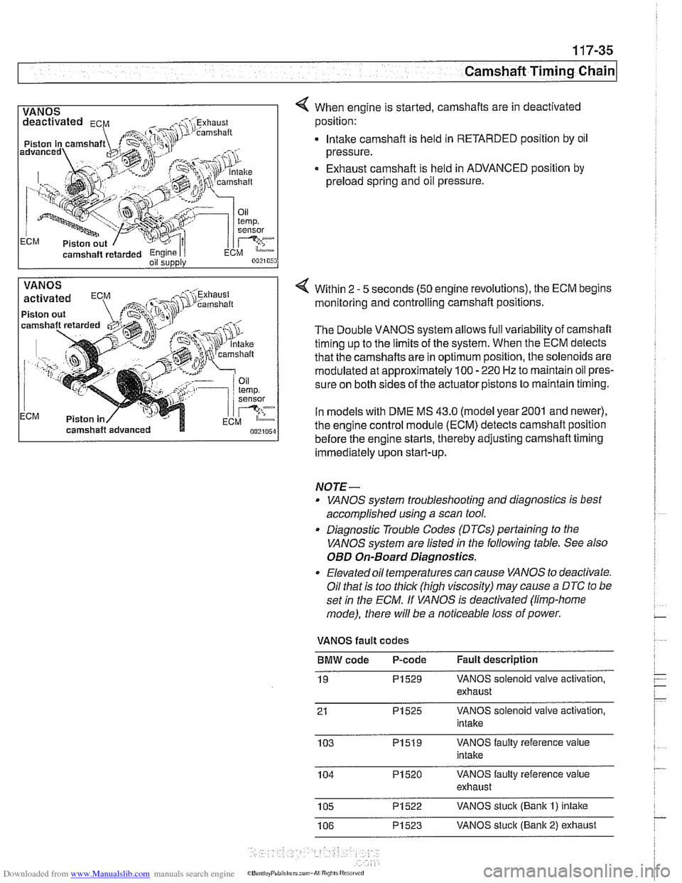
1 VANOS I 4 When engine is started, camshafts are in deactivated
camshaft
retarded Engine I i oil supply
position:
. lntalte camshaft is held in RETARDED position by oil
pressure.
Exhaust camshaft is held in ADVANCED position by
preload spring and oil pressure.
VANOS
Piston out
ECM Piston in Within 2
- 5
seconds (50 engine revolutions), the ECM begins
monitoring and controlling camshaft positions.
The Double VANOS system allows full variability of camshaft
timing up to the limits of the system. When the ECM detects
that the camshafts are in optimum position, the solenoids are
modulated at approximately 100
- 220 Hz to maintain oil pres-
sure on both sides of the actuator pistons to maintain timing.
In models with DME
MS 43.0 (model year2001 and newer),
the engine control module (ECM) detects camshaft position
before the engine starts, thereby adjusting camshaft timing
immediately upon start-up.
NOTE-
. VANOS system troubleshooting and diagnostics is best
accomplished using a scan tool.
. Diagnostic Trouble Codes (DTCs) pertaining to the
VANOS system are listed
in the following table. See also
OED On-Board Diagnostics.
Elevated oil temperatures can cause VANOS to deactivate.
Oil that is too thick (high viscosity) may cause
a DTC to be
set
in the ECM. If VANOS is deactivated (limp-home
mode), there will be a noticeable loss of power.
VANOS fault codes
BMW code P-code Fault description
19
PI529 VANOS solenoid valve activation,
exhaust
21
PI525 VANOS solenoid valve activation,
intake
103
PI519 VANOS faulty reference value
intake
104
PI520 VANOS faulty reference value
exhaust
105
PI522 VANOS stuck (Bank I) intake
106
PI523 VANOS stuck (Bank 2) exhaust
Page 340 of 1002
Downloaded from www.Manualslib.com manuals search engine
Lubr~cat~on System r- -
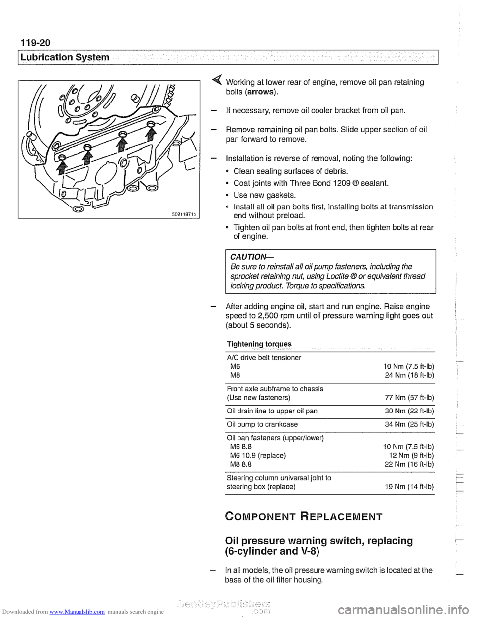
Working at lower rear of engine, remove oil pan retaining
bolts
(arrows).
- If necessary, remove oil cooler bracket from oil pan.
- Remove remaining oil pan bolts. Slide upper section of oil
pan forward to remove.
- Installation is reverse of removal, noting the following:
Clean sealing surfaces of debris.
- Coat joints with Three Bond 1209 O sealant.
Use new gaskets.
Install all oil pan bolts first, installing bolts at transmission
end without preload.
Tighten oil pan bolts at front end, then tighten bolts at rear
of engine.
Be sure to reinstall all oil
pump fasteners, including the
sprocl
speed to
2,500 rpm until oil pressure warning light goes out
(about
5 seconds).
Tightening torques
AIC drive belt tensloner
M6 10 Nm (7.5 it-lb)
M8 24 Nm (18 ft-lb)
Front axle
subframe to chassis
(Use new fasteners) 77 Nm (57 ft-lb)
Oil drain
line to upper oil pan 30 Nm (22 ft-lb)
Oil pump to crankcase 34 Nm (25 ft-lb)
Oil pan fasteners
(upperllower)
M6 8.8 10 Nm (7.5 ft-lb)
M6 10.9 (replace)
I2 Nm (9 ft-lb)
M8 8.8 22 Nm (16 ft-lb)
Steering column universal joint to
steering box (replace) 19 Nm (14 ft-lb)
Oil pressure warning switch, replacing
(&cylinder and V-8)
- In all models, the oil pressure warning switch is located at the
base of the oil filter housing.
Page 354 of 1002
Downloaded from www.Manualslib.com manuals search engine
120-6
lgnition System
lgnition system, troubleshooting
Troubleshooting ignition system faults should begin with an
interrogation of the On-Board Diagnostics (OBD
II) system.
The OBD
II system detects ignition system misfire and other
related faults. When faults are detected, the OBD
II system
stores a Diagnostic Trouble Code (DTC) in the Engine Con-
trol Module (ECM) along with other pertinent fault information.
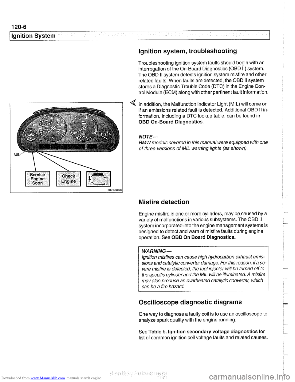
4 In addition, the Malfunction Indicator Light (MIL) will come on
if an emissions related fault is detected. Additional OBD
II in-
formation, including a DTC lookup table, can be found in
OED On-Board Diagnostics.
NOTE-
BMWmodels covered in this manual were equipped with one
of three versions of
MIL warning lights (as shown).
Misfire detection
Engine m~sfire in one or more cylinders, may be caused by a
var~ety of malfunctions in various subsystems. The OBD II
system ~ncorporated into the engine management systems is
des~gned to detect and warn of misfire faults during englne
operat~on. See OED On Board Diagnostics.
WARNING -
lgnition misfires can cause high hydrocarbon exhaust emis-
sions andcatalytic converter damage. For this reason, if a se-
vere misfire is detected, the fuel injector
will be turned off to
the specific cylinder and the
MIL will be illuminated. A misfire
may also produce an overheated catalytic converter, which
can be a fire hazard.
Oscilloscope diagnostic diagrams
One way to diagnose a faulty coil is to use an oscilloscope to
analyze spark quality with the engine running.
See Table b. lgnition secondary voltage diagnostics for
list of common ignition
coil voltage faults and related causes.
Page 357 of 1002
Downloaded from www.Manualslib.com manuals search engine
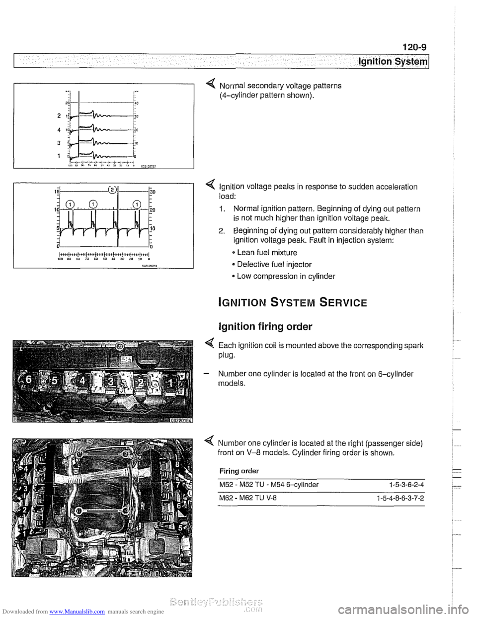
< Ignition voltage peaks in response to sudden acceleration
load:
1. Normal ignition pattern. Beginning of dying out pattern
is not much higher than ignition voltage peak.
2. Beginning of dying out pattern considerably higher than
ignition voltage peak. Fault in injection system:
Lean fuel mixture
Defective fuel injector
Low compression in cylinder
-, :I 1- i :
Ignition firing order
Normal secondary voltage patterns
(4-cylinder pattern shown).
4 Each ignition coil is mounted above the corresponding spark
plug.
- Number one cylinder is located at the front on 6-cylinder
models.
Number one cylinder is located at the right (passenger side)
front on
V-8 models. Cylinder firing order is shown.
Firing order
M52 - M52 TU - M54 6-cylinder 1-5-3-6-2-4
M62 - M62 TU V-8 1-5-4-8-6-3-7-2
Page 370 of 1002
Downloaded from www.Manualslib.com manuals search engine
.-. .
Battery, Starter, Alternator
Warnings and cautions
WARNING -
Wear goggles, rubber gloves, and a rubber apron when
working around the battery or battery acid (electrolyte).
Battery acid contains sulfuric acid and can cause skin
irritation and burning.
If acid is spilled on your skin or
clothing, flush the area at once with large quantities of
water. If electrolyte gets into your eyes, flush them with
large quantities of clean water for several minutes and
call a physician.
Batteries that are being charged or are fully charged
give off explosive hydrogen gas. Keep sparks and open
flames away. Do not
smoke.
CA UTIOI\C
Only use a digital multimeter when testing automotive elec-
trical components.
. If a repair procedure specifies disconnecting the bat-
tery, follow the instruction for safety reasons.
Prior to disconnecting the battery, read the battery dis-
connection cautions in
001 General Cautions and
Warnings.
Models with MS43 engine management: Allow at least
3 minutes to elapse after turning ignition ley to OFFpo-
sition before disconnecting battery. This willallow sum-
cient tinie to complete the DMJL (fuel tank pressure)
test
* Disconnecting the battery cables may erase fault codes
stored in ECM memory.
Always disconnect the negative
(-) battery cable first
and reconnect it last. Cover the battery post with an in-
sulating material whenever the cable is removed.
Do not disconnect battery, alternator or starter wires
while the engine is running.
0 Never reverse the battery cables. Even a momentary
wrong connection can damage the alternator or other
electrical components.
Do not depend on the color of insulation to tell battery
positive and negative cables apart. Label cables before
removing.
The slide-tilt sunroof may fail to function properly
after
disconnecting and reconnecting the battery. Reinitial-
ize sunroof as described in 540 Sunroof.
Page 378 of 1002
Downloaded from www.Manualslib.com manuals search engine
Battery, Starter, Alternator
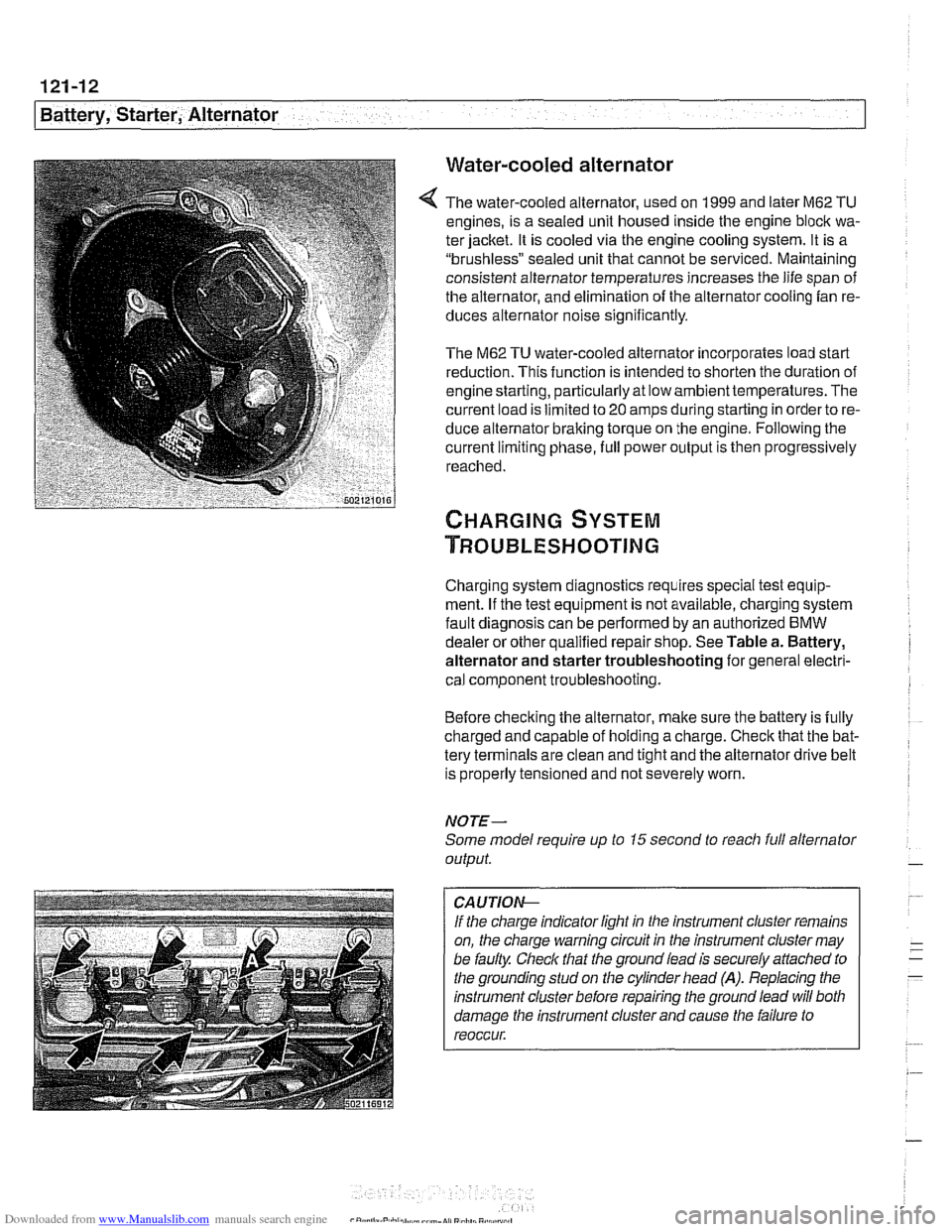
Water-cooled alternator
The water-cooled alternator, used on 1999 and later M62 TU
engines, is a sealed unit housed inside the engine block wa-
ter jacket. It is cooled via the engine cooling system. It is a
"brushless" sealed unit that cannot be serviced. Maintaining
consistent alternator temperatures increases the life span of
the alternator, and elimination of the alternator cooling fan re-
duces alternator noise
significantly.
The M62 TU water-cooled alternator incorporates load start
reduction. This function is intended to shorten the duration of
engine starting, particularly at low ambienttemperatures. The
current load is limited to
20 amps during starting in order to re-
duce alternator braking torque on the engine. Following the
current limiting phase, full power output is then progressively
reached.
Charging system diagnostics requires special test equip-
ment. If the test equipment is not available, charging system
fault diagnosis can be performed by an authorized
BMW
dealer or other qualified repair shop. See Table a. Battery,
alternator and starter troubleshooting for general electri-
cal component troubleshooting.
Before checking the alternator, make sure the battery is fully
charged and capable of holding a charge. Check that the bat-
tery terminals are clean and tight and the alternator drive belt
is properly tensioned and not severely worn.
NOTE-
Some model require up to 15 second to reacli full alternator
output.
CA UTIOG
If the charge indicator light in the instrument cluster remains
on, the charge warning circuit in the instrument cluster may
be faulty. Check that the ground lead is securely
affached to
the grounding stud on the cylinder head
(A). Replacing the
instrument cluster before repairing the ground lead will both
damage the instrument cluster and cause the failure to
reoccur.
Page 429 of 1002
Downloaded from www.Manualslib.com manuals search engine
. .
Fuel Injection
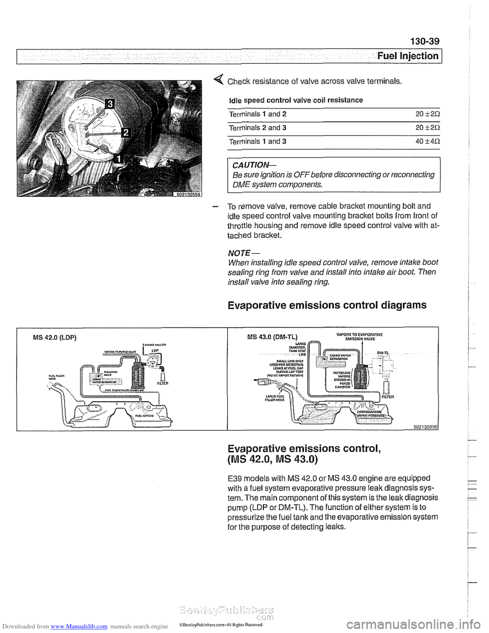
Check resistance of valve across valve terminals
Idle speed control valve coil resistance
Terminals
1 and 2 20 i2.0.
Terminals 2 and 3 20 i2.0.
Terminals 1 and 3 40 i4.0.
CAUTIOIG
Be sure ignition is OFFbefore disconnecting or reconnecting
DME system components.
- To remove valve, remove cable bracket mounting bolt and
idle speed control valve mounting bracket bolts from front of
throttle housing and remove idle speed control valve with at-
tached bracket.
NOTE-
When installing idle speed control valve, remove intake boot
sealing ring from valve and install into intake air boot. Then
install valve info sealing
ring.
Evaporative emissions control diagrams
MS 42.0 (LDP) ,-a"-
Evaporative emissions control,
(MS 42.0, MS 43.0)
E39 models with MS 42.0 or MS 43.0 engine are equipped
with a fuel system evaporative pressure leak diagnosis sys-
tem. The main component of this system is the leak diagnosis
pump (LDP or DM-TL). The function of either system is to
pressurize the fuel tank and the evaporative emission system
for the purpose of detecting leaks.