alternator belt BMW 540i 1998 E39 User Guide
[x] Cancel search | Manufacturer: BMW, Model Year: 1998, Model line: 540i, Model: BMW 540i 1998 E39Pages: 1002
Page 381 of 1002
Downloaded from www.Manualslib.com manuals search engine
Battery, Starter, ~lternatorl
Alternator, removing and installing
(6-cylinder engine)
A replacement alternator should have the same rating as the
original. Alternator manufacturer and ampere rating are nor-
mally marked on the alternator housing.
- Disconnect negative (-) battery cable.
CAUTION-
Prior to disconnecting the batteg read the battery discon-
nection cautions given
in 001 General Warnings and Cau-
I tions.
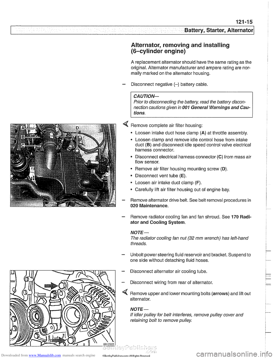
Remove complete air filter housing:
Loosen intake duct hose clamp
(A) at throttle assembly.
Loosen clamp and remove idle control hose from intake
duct
(B) and disconnect idle speed control valve electrical
harness connector.
Disconnect electrical harness connector
(C) from mass air
flow sensor.
* Remove air filter housing mounting screw (D),
Disconnect vent tube (E).
Loosen air intake duct clamp (F).
Carefully lifl air filter housing out of engine bay.
Remove alternator drive belt. See belt removal procedures in
020 Maintenance.
- Remove radiator cooling fan and fan shroud. See 170 Radi-
ator and Cooling System.
NOTE-
The radiator cooling fan nut (32 mm wrench) has left-hand
threads.
- Unbolt power steering fluid reservoir and bracket. Suspend to
one side without detaching fluid hoses.
- Disconnect alternator air cooling tube.
- Disconnect wiring from rear of alternator.
'4 Remove upper and lower mounting bolts (arrows) and lift
alternator.
If idler pulley for belt interferes, remove pulley cover and
retaining bolt to remove pulley. out
Page 382 of 1002
Downloaded from www.Manualslib.com manuals search engine
121-16
Battery, Starter, Alternator
- installation is reverse of removal.
Tightening torques Belt tensloner to engine block
M8 (8.8 grade) 22
Nm (16 ft-ib)
Fan clutch to coolant pump
with BMW special tool 11
5 040 30 Nm (22
ft-lb)
without BMW special tool
11 5 040 40 Nm
(29 ft-ib)
Pulley to alternator 70
Nm (44 ft-lb)
Terminal 30
(B+) wire to alternator (M8) 13 Nm (10 ft-ib)
Alternator, removing and installing
(M62 engine, air cooled)
A replacement alternator should have the same rating as the
original. Alternator manufacturer and ampere rating are nor-
mally
marked on the alternator housing.
- Disconnect negative (-) battery cable.
CAUTION-
Prior to disconnecting the battery, read the battery discon-
nection cautions
001 General Warnings and Cautions.
- Remove cooling fan and alternator drive belt. See 020 Main-
tenance.
- Pry out trim caps and remove fasteners from plastic cover on
left head. Lift off cover.
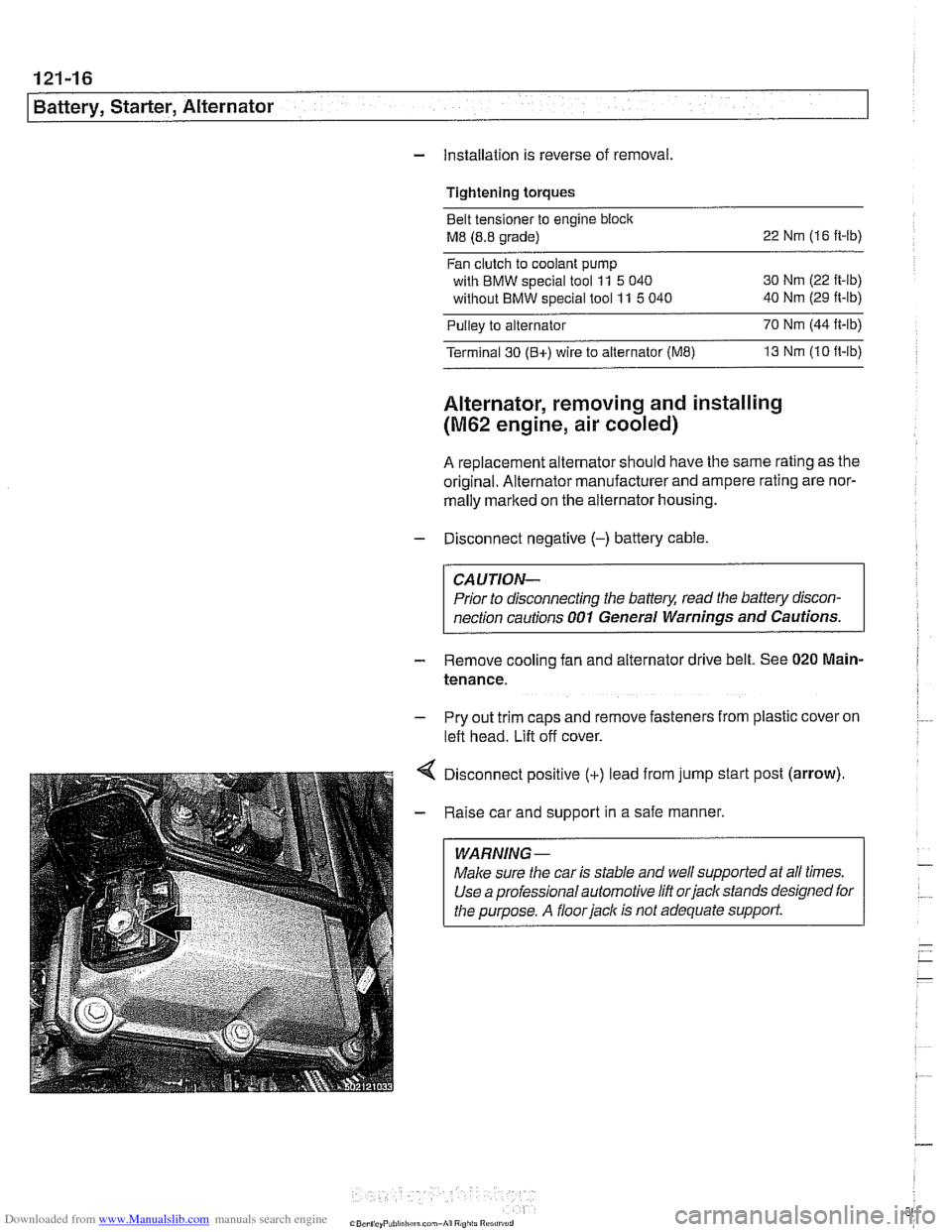
Disconnect positive
(+) lead from jump start post (arrow).
Raise car and support in a safe manner.
WARNING-
Make sure the car is stable and well supported at aN times.
Use a professional automotive lift
orjack stands designed for
the purpose.
A floorjack is not adequate support.
Page 384 of 1002
Downloaded from www.Manualslib.com manuals search engine
121-18
I Battery, Starter, Alternator
Alternator, removing and installing
(M62 TU engine, water cooled)
V-8 models produced after 9/98 are equipped with a water
cooled alternator.
CAUTION-
Allow engine to cool before removing alternator as coolant
will
escape from the alternator water jacket.
- Disconnect negative (-) battery cable
CAUTION- Prior to disconnecting the
battew read the battery discon-
nection cautions given in
001 General Warnings and Cau-
tions.
- Remove radiator cooling fan and fan shroud. See 170 Radi-
ator and Cooling System.
- Drain engine cooling system. See 170 Radiator and Cool-
ing System.
- Remove alternator drive belt. See 020 Maintenance.
- Disconnect battery lead (terminal 30 or B+) and two-pin har-
ness connector from front of alternator.
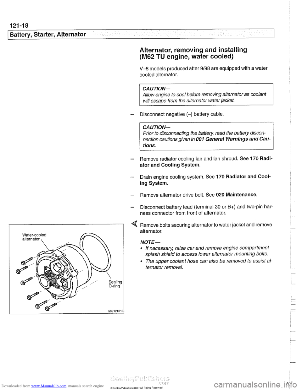
I < Remove bolts securing alternator to water jacket and remove
aling ring
alternator.
NOTE- If necessary, raise car and remove engine compartment
splash shield to access lower alternator mounting bolts.
The upper coolant hose can also
be removed to assist al-
ternator removal.
Page 675 of 1002
Downloaded from www.Manualslib.com manuals search engine
Steering and Wheel Alignment
Power assist is provided by a belt-driven pump at the lower
left front of the engine. The power steering fluid reservoir is lo-
cated at the left side of the engine compartment.
Power steering pump, removing and
installing
When working with power steering components, absolute
cleanliness is needed to ensure proper operation of the hy-
- Empty power steering fluid reservoir using clean syringe. Do
not reuse fluid.
- Raise front of car. Remove splash shield from under engine.
WARNING-
Make sure the car is firmly supported on jack stands de-
signed for the purpose. Place jack stands beneath structural
chassis points. Do not place jack stands under suspension
Darts.
Remove drive belt from power steering pump. See
020 Main-
tenance.
Remove alternator cooling duct
Remove fluid hoses from pump. Plug openings in pump and
hose ends.
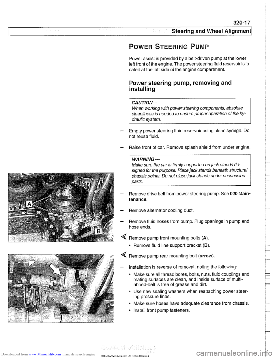
Remove pump front mounting bolts
(A).
Remove fluid line support bracket (B)
Remove pump rear mounting bolt (arrow)
- Installation is reverse of removal, noting the following:
Make sure all thread bores, bolts, nuts, fluid couplings and
mating
surfaces are clean, and inside surface of multi-
ribbed-belt is free of grease and dirt.
Use new sealing washers when reattaching power steer-
ing pressure lines.
Make sure hoses have adequate clearance from chassis.
Install front pump fasteners.
Page 991 of 1002
Downloaded from www.Manualslib.com manuals search engine
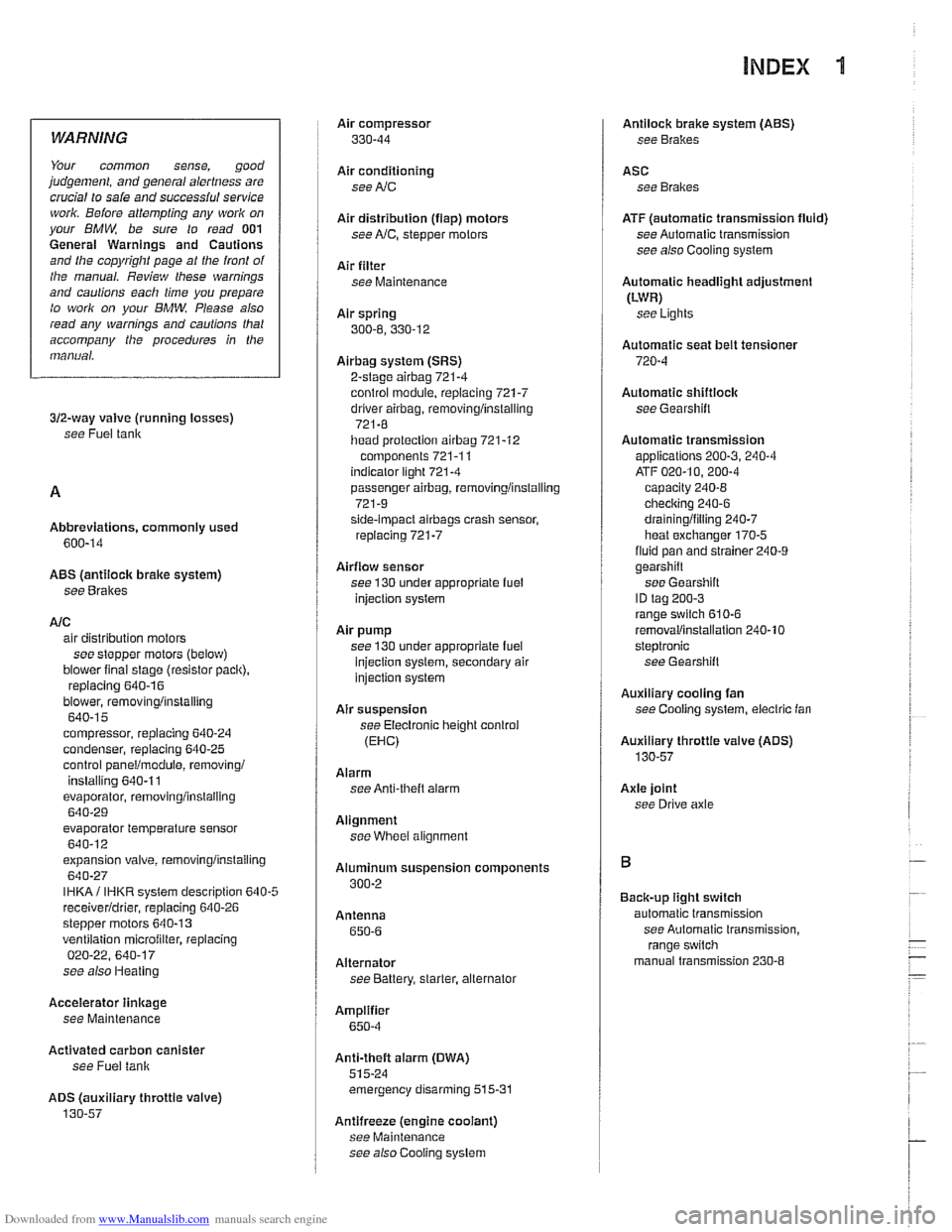
INDEX 'tl
WARNING
Your common sense, good
judgemenl, and general alertness are
crucial to sale and successiul service
worlr. Belore attempting any work on
your
BMM be sure lo read 001
General Warnings and Cautions
and the
copyriglll page at the front 01
the manual. Review these warnings
and
caulions each lime you prepare
lo work on your BMW. Please also
read any warnings and cautions that
accompany
tile procedures in the
manual.
312-way valve (running losses)
see Fuel tank
Abbreviations, commonly used 600-14
ABS (antilock brake system)
see
Bral(es
A/C air distribution motors
see stepper motors (below)
blower final stage (resistor pack),
replacing
640-16
blower, removinglinslalling
640-1 5
compressor, replacing
640-24 condenser, replacing 64045
control panellmodule, removing1
installing
640-1 1
evaporakr, removinglinstalling 640-29
evaporator temperature sensor
640-12 expansion valve, removinglinstailing
640-27
IHKA/ IHKR system description 640-5
receiveridrier, replacing 640-26
stepper motors 640-1 3 ventilation microiilter, replacing
020-22. 640-17
see also Heating
Accelerator
iinlcage
see Maintenance
Activated carbon canister
see Fuel tank
ADS (auxiliary throttle valve)
130-57
Air compressor
330-44
Air conditioning
see
AIC
Air distribution (flap) motors
seeNC, stepper motors
Air filter see Maintenance
Air spring
300-6, 330-12
Airbag system (SRS)
2-stage
airbag 721-4
control module, replacing 721-7 driver airbag, removinglinstalling
721-8
iiead protection airbag 721-12 components 721-1 1
indicator
lighl721-4
passenger airbag, removinglinstalling
721-9 side-impact airbags crash sensor,
replacing
721-7
Airflow sensor see 130 under appropriate
fuel
injection system
Air pump
see 130 under appropriate fuel
injection system, secondary air
injection system
Air suspension
see Electronic height control
(EHC)
Alarm
see Anti-theft alarm
Alignment see
Wheei alignment
Aluminum suspension components
300-2
Antenna 650-6
Alternator see Battery, starter, alte rnator
Amplifier
650-4
Anti-theft alarm (DWA)
515-24 emergency disarming 515-31
Antifreeze (engine coolant)
see Maintenance
see also Cooling system
Antilock brake system (ABS) see Brakes
ASC see Brakes
ATF (automatic transmission fluid)
see Automatic transmission
see also Cooling systern
Automatic headlight adjustmenl
(LWR) see Lights
Automatic seat belt tensioner
720-4
Automatic shiftloclc
see
Gearshift
Automatic transmission
applications
200-3, 240-4
ATF 020-10, 200-4
capacity 240-8 checking 240-6
drainingifilling 240-7
heat exchanger 170-5
fluid pan and strainer 240-9 gearshift
see Gearshift
ID tag
200-3 range switch 610-6
removaliinstallation 240-10
steptronic see Gearshift
Auxiliary cooling fan
see
Coollng system, electric Ian
Auxiliary throttle valve (ADS)
130-57
Axle joint
see Drive axle
Back-up light switch
automatic transmission see Automatic transmission. range switch
- .~.~~~
manual transmission 230-8 -
- I
Page 992 of 1002
Downloaded from www.Manualslib.com manuals search engine
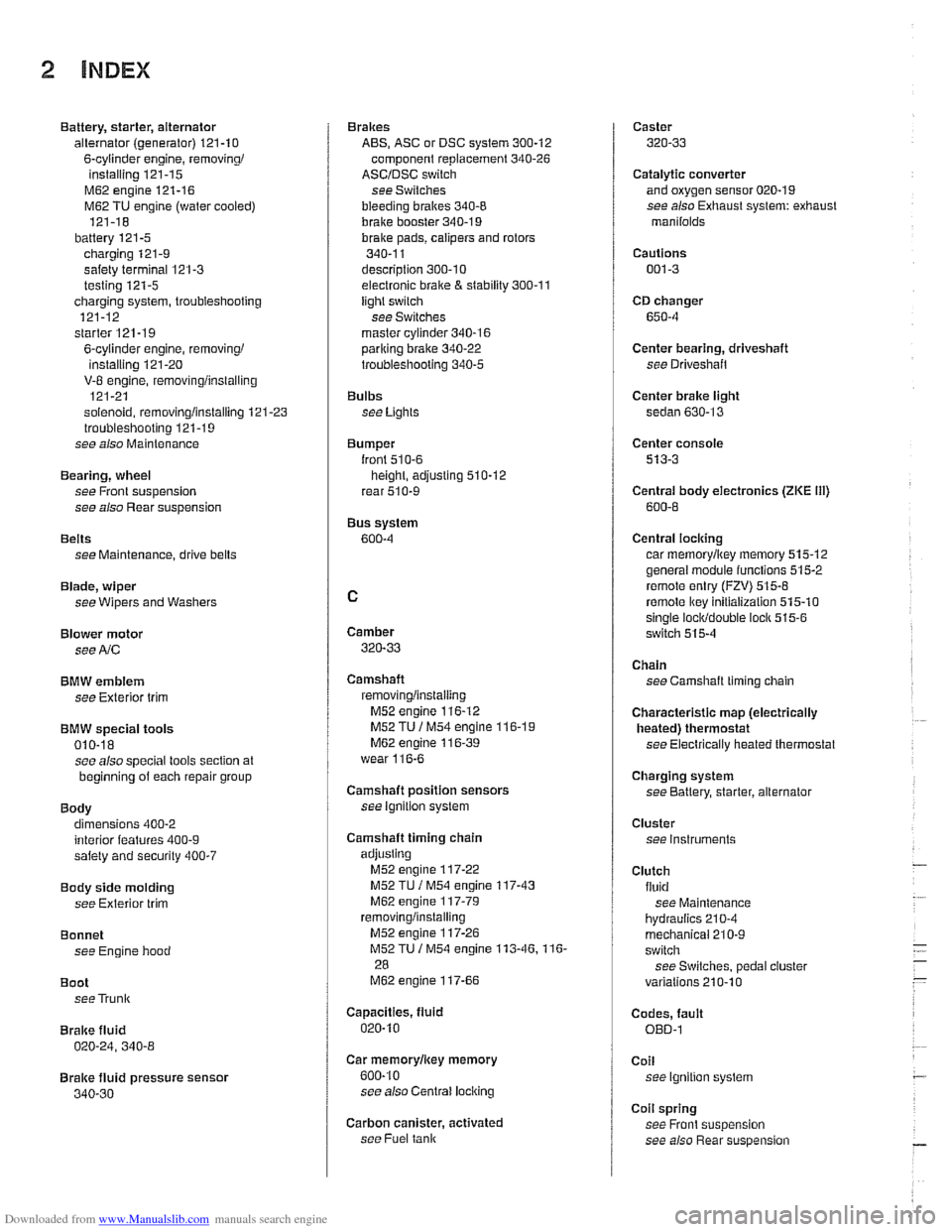
2 INDEX
Battery, starter, alternator
alternator (generator)
121-10
6-cylinder engine, removingi
installing 121-15
M62 engine 121-16
M62 TU engine (water cooled)
121-18
battery
121-5 charging 121-9
safety terminal 121-3
testing 121-5 charging system, troubleshooting
121-12
starter
121-1 9
6-cylinder engine, removingi instaliinq 121-20 . V-8 engine, rernovinglinsialiing
121-21
solenoid, removinglinstalling
121-23 troubleshooting 121-19
see also Maintenance
Bearing, wheel
see Front suspension
see also Rear suspension
Belts see Maintenance, drive belts
Blade, wiper
see Wipers and Washers
Blower motor see
A/C
BMW emblem
see Exterior trim
BMW special tools 010-18 see also special tools section at
beginning
of each repair group
Body dimensions 400-2
interior features
400-9 salety and security 400-7
Body side molding
see Exterior trim
Bonnet see Engine hood
Boot see Trunk
Brake fluid
020-24, 340-8
Brake fluid pressure sensor
340-30
Brakes
ABS, ASC or DSC system
300-12
component replacement 340-26
ASCIDSC switch
see Switches
bleeding
bralces 340-8
brake booster 340-1 9 bralce Dads. caiioers and rotors ,., 340-1 1
descriotion 300-10
e~ectrdnic brake & stability 300-11
light switch
see Switches
master cylinder
340-16 pariking brake 340-22
troubleshooting 340-5
Bulbs see Lights
Bumper
lront 510-6 height, adjusting 510-12
rear 510-9
Bus system
600-4
Camber
320-33
Camshaft
removingiinslaiiing
M52 engine 116-12
M52 TU
/ M54 engine 116-1 9 M62 engine 11 6-39
wear
116-6
Camshaft position sensors
see ignition system
Camshaft timing chain
adjusting M52 engine
117-22
M52 TU I M54 engine 117-43
M62 engine 117-79 removinglinstalling
M52 engine 117-26
M52TU 1 M54 engine 113-46.116-
28
M62 engine 117-66
Capacities, fluid
020.10
Car rnemorvlicev memorv . . 600-10
see also Centrai
lociking
Carbon canister, activated
see Fuel
tank
Caster
320-33
Catalytic converter and oxygen sensor 020-19
see also Exhaust system: exhaust
manilolds
Cautions
001-3
CD changer
650-4
Center bearing, driveshaft
see Driveshait
Center brake light
sedan
630-13
Center console
513-3
Centrai body electronics (ZKE 111)
600-6
Central locking
car memoryiey memory 515.12 general module iunctions 515-2
remote entry (FZV) 515-8
remote lkey initialization 515-10 single lociddouble ioclk 515-6
switch 515-4
Chain
see Camshaft liming chain
Characteristic map (electrically heated) thermostat
see Electrically heated thermostat
Charging system
see Battery, starter, alternator
Cluster see instruments
Clutch fluid see Maintenance
hydraulics
210-4
mechanical 210-9
switch
see Switches, pedal ciuster
variations
210.10
Codes, fault OED-1
Coil
see Ignition system
Coil spring
see Front suspension
see also Rear
suspe nsion
Page 999 of 1002
Downloaded from www.Manualslib.com manuals search engine
INDEX 9
WARNING
Your common sense, good judgemenl, and general alerlness are
crucial lo seie end successful service
ivork. Beiore attempting any work on
your
BMW be sure to read 001
General Warnings and Cautions and llle copyright page at lhe iron1 of
the manual. Review Niese warnings
and caulions each lime you prepare
lo work on your BMW Please also
read any warnings and caulions lllal accompany the procedures in the
manual.
Rear suspension
ball joints
330-19
bushings 330-13
control arms
seesuspension arms, below
description
300-5
electronic height control (EHC)
330-44
ride height 300-14 ride height sensor 330-46
shoclr absorbers end springs 330-9
stabilizer bar 330-42
struts and springs 330-5 subframe 330.13
suspension arms 330-13
variations 330-4 wheel bearing, replacing 330-32
see also Maintenance
see also Drive axles
see also Final drive
Rear window (Sport Wagon)
see
Tailgate
Rear window defroster 610-17
Receiverldrter
see NC
Relay positions
see Electrical component tocations
table 610-3
Remote entry (FZV)
see Central locking
Reversing light switch
see
Baclc-up light switch
Ride height
300-14
Ride height sensor
see Rear suspension
Ring antenna
see EWS (electronic immobilizalion)
Rotor
see Brakes
Roundel see Exterior trim
Running tosses
(312-way) valve
see Fuel
tenlr
SCA (soft close)
seeTailgate, soft close
see also Trunk lid. soft close
Scan tools
OED-3
Seals gaskets and 010-9
see also Crankshaft seals
Seat front,
removing/instelling 520-10
memory system 520-4 rear 520-13
see also Seat belt
Seat beit front 720-4
rear 720-8
troubleshooting 7202
see also Maintenance
Secondary air injection
see 130 under appropriate
iuel
injection system
Selector shaft seat
see Manual transmission, oil
Seals
Self-adjusting ctulch (SAC)
see Clutch, variations
Service indicator see Maintenance
Shift interlock see Gearshift
Shift lever
see
Gearshift
Shift linkage see Gearshift
Shiftlock see Gearshilt
Shack absorber see Rear suspension
/ Side turn signal assembly
see Lights
Sill trim panel
411-10
Slave cylinder
see Clutch, lhydraulic
Steep mode
600-1 1
Soft close
(SCA) see Tailgate
see also
Trunk lid
Solenoid 121-23
Sound system
650-2
Spare parts kit
010-21
Spark plugs
see Maintenance
Speakers
650-4
Specifications, fluid
020-4
Sport wagon
400-4
Springs
see Front suspension
see also Rear suspension
SRS (supplemental restraint system)
see
Airbag system (SRS)
Stabilizer bar see Front suspension
see also Rear suspension
Starter see Battery, starter, alternator