battery replacement BMW 540i 1998 E39 User Guide
[x] Cancel search | Manufacturer: BMW, Model Year: 1998, Model line: 540i, Model: BMW 540i 1998 E39Pages: 1002
Page 479 of 1002
Downloaded from www.Manualslib.com manuals search engine
.- -
Fuel Tank and Fuel purnpl
Fuel pump power consumption, testing
To achieve accurate test results, the battery voltage at the
fuel pump connector should be
12.6 volts. Charge the battery
as necessary.
A higher than normal power consumption may indicate a
worn fuel pump, which may cause intermittent fuel starvation
due to pump overheating and seizure. The only remedy is
pump replacement.
A lower than normal power consumption
may indicate a blockage. Be sure to check that the return line
and the pump pickup are not obstructed before replacing the
pump.
- Expose right side access cover:
Peel forward lip of carpet.
Release rubber grommet from center of access cover insu-
lation.
Peel back insulation at perforations to expose fuel tank ac-
cess cover.
Remove right side cover to expose electrical harness con-
nector.
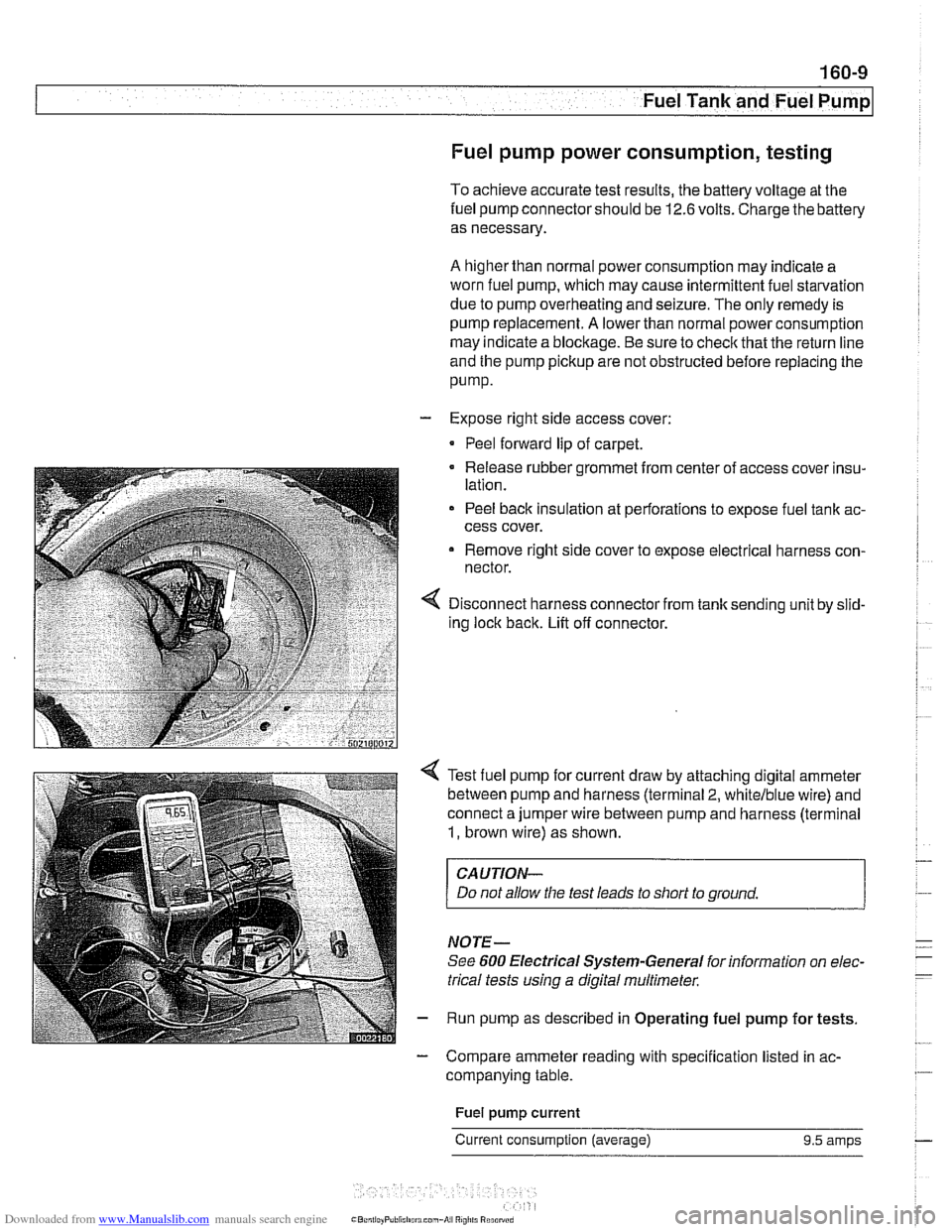
Disconnect harness connector from tank sending unit by slid-
ing lock back. Lift off connector.
Test fuel pump for current draw by attaching digital ammeter
between pump and harness (terminal
2, whitelblue wire) and
connect a jumper wire between pump and harness (terminal
1, brown wire) as shown.
CAUTION-
Do not allow the test leads to short to ground.
NOTE-
See 600 Electrical Systern-General for information on elec-
trical tests
using a digital multirneter.
Run pump as described in Operating fuel pump for tests.
- Compare ammeter reading with specification listed in ac-
companying table.
Fuel
pump current
Current consumption (average) 9.5 amps
Page 638 of 1002
Downloaded from www.Manualslib.com manuals search engine
31 0-2
I Front Suspension
This repair group covers the repair and replacement of com-
ponents that make up the front suspension of E39 cars.
Two different types of steering systems are used in the E39
series. 6-cylinder
(5251,5281 and 530i) models are equipped
with a rack and pinion type steering system mounted to an
aluminum subframe.
V-8 (540i) models use a steering gear-
box type system mounted to a steel subframe.
See
300 Suspension, Steering and Brakes-General for a
description of the front suspension and components, as well
as specifications for setting ride height.
CAUTION-
Some E39 models are equipped with aluminum suspen-
sion components. The foiiowing cautions apply:
Due to the chemical and corrosion characteristics of
aluminum, do not bring into contact with battery acid.
* Do not clean with wire brushes with brass or iron bris-
ties. Only use brushes with stainless steei bristles.
Do not expose to flying sparks from grinding/cutting op-
erations.
* Do not subject to steei welding splashes.
Do not expose to temperatures over 80°C (176°F).
even for short periods. Temperatures in painting faciii-
ties are not a problem.
Special tools
Special service tools are required for most of the work de-
scribed in this repair group. In addition to the tools depicted in
the illustrations, avariety of press tools are necessaryfor con-
trol arm bushing replacement. Read the procedures through
before beginning any job.
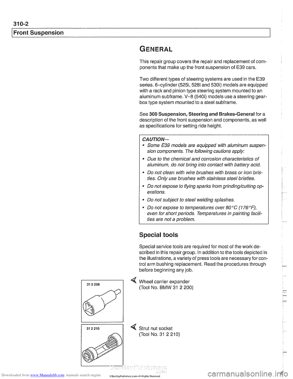
31 2 210 I < Strut nut socket
(Tool No. 31 2 210)
Page 698 of 1002
Downloaded from www.Manualslib.com manuals search engine
330-2
I Rear Suspension
This repair group covers removal and replacement of E39
rear suspension components. A general description of sus-
pension systems and ride height specifications can be found
in 300 Suspension, Steering and Brakes - General.
CAUTIOI\C
Some E39 models are equipped with aluminum suspen-
sion components. The following cautions apply:
Due to the chemical and corrosion characteristics of
aluminum, do not bring into contact with battery acid.
- Do not clean with wire brushes with brass or iron bris-
tles. Only use brushes with stainless steel bristles.
Do not expose to flying
sparl~s from grinding/cutting op-
erations.
* Do not subject to steel welding splashes.
0 Do not expose to temperatures over 80°C (176°F).
even for shortperlods. Temperatures in painting facili-
ties are not a problem.
Special tools
Special service tools are required for some of the work de-
scribed in this repair group. Most of these tools are special-
ized press jigs and pullers that might be replaced by standard
pullers of various sizes.
Read the procedures through before beginning any job.
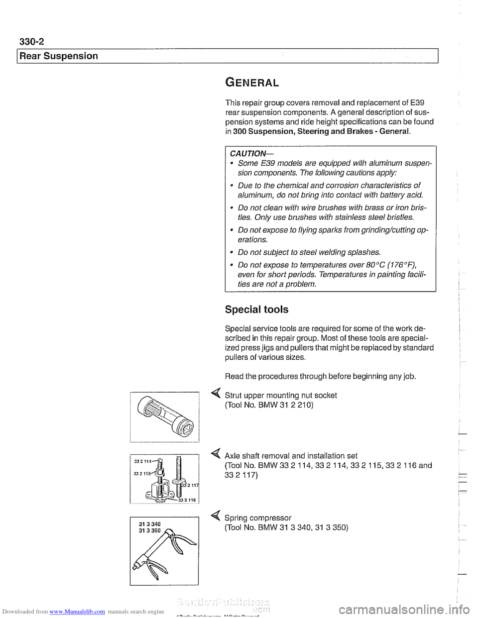
< Strut upper mounting nut socket
(Tool No. BMW
31 2 21 0)
I Axle shaft removal and installation set
Spring compressor (Tool No. BMW
31 3 340.31 3 350)
Page 820 of 1002
Downloaded from www.Manualslib.com manuals search engine
Doors
This repair group covers front and rear door repair informa-
tion. It includes removal and installation of front and rear
doors and trim panels.
For information on
airbag removal and installation, see 721
airbag.
For information on the power door windows and door glass
replacement, see
512 Door Windows.
For information on the power door
loclting system, see 515
Central Locking and Anti-Theft.
WARNING-
E39 cars are fitted with side-impact airbags in the front doors
and optional side impact
airbags in the rear doors. When
servicing doors, always disconnect the negative
(-) battery
terminal. See
721 Airbag System (SRS) for cautions and
procedures
relatinq to the airbaq system.
Front or rear door, removing and installing
- Disconnect negative (-) battery cable.
Prior to disconnecting the battery, read the battery discon-
nection cautionsgiven in
001 General Cautions and warn-
ings.
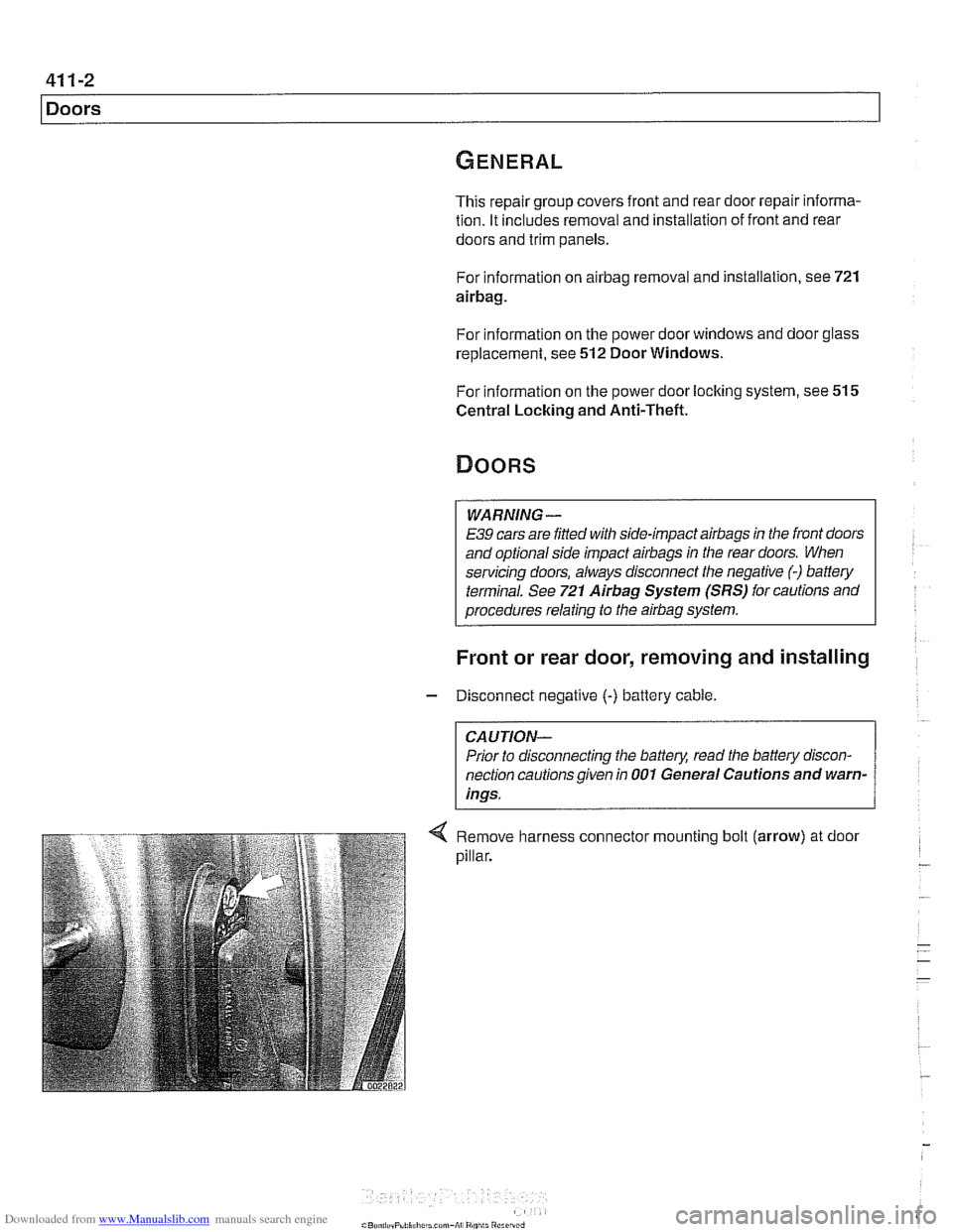
Remove harness connector mounting bolt (arrow) at door
pillar.
Page 906 of 1002
Downloaded from www.Manualslib.com manuals search engine
51 5-12
I Central Locking and Anti-Theft
Key battery
9
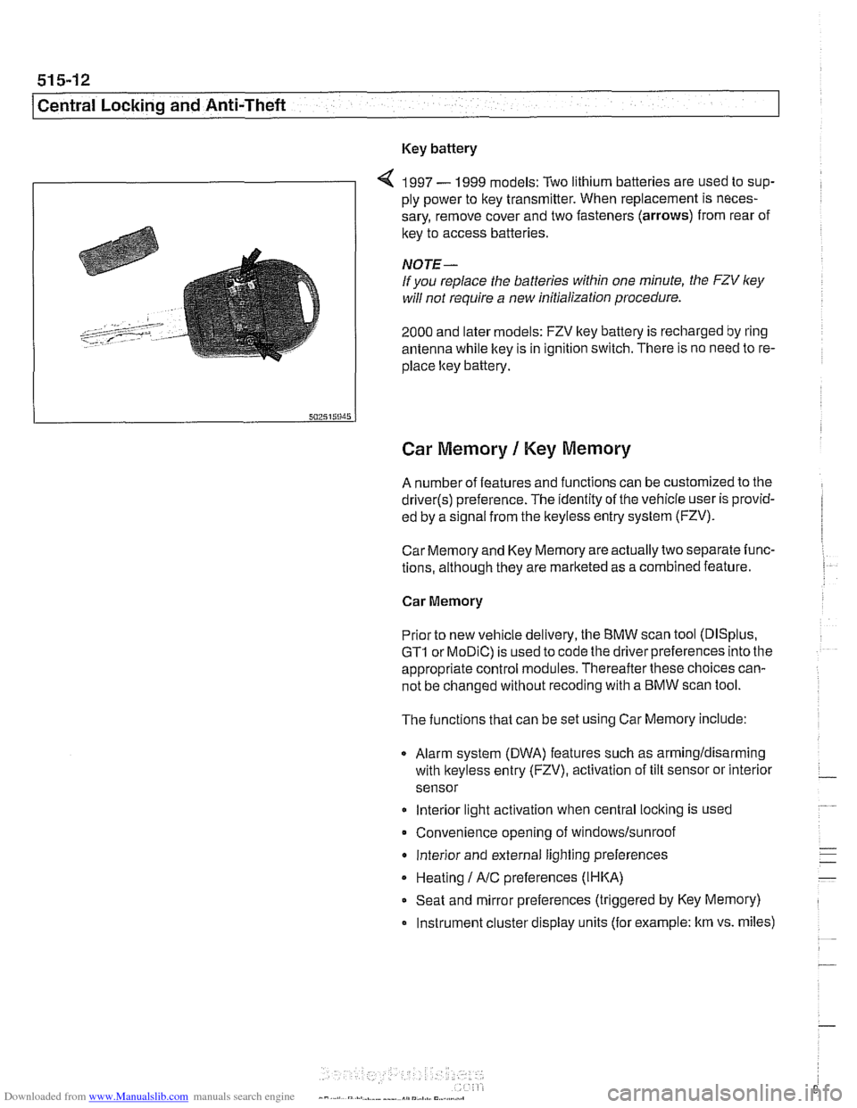
4 1997 - 1999 models: Two lithium batteries are used to sup-
ply power to key transmitter. When replacement is neces-
sary, remove cover and two fasteners (arrows) from rear of
key to access batteries
NOTE-
If you replace the batteries within one minute, the FZV ley
will not require a new initialization procedure.
2000 and later models: FZV key battery is recharged by ring
antenna while ltey is in ignition switch. There is no need to re-
place ltey battery.
Car Memory 1 Key Memory
A number of features and functions can be customized to the
driver(s) preference. The identity of the vehicle user is provid-
ed by a
s~gnal from the keyless entry system (FZV).
Car Memory and Key Memory are actually two separate func-
tions, although they are marketed as a combined feature.
Car Memory
Pr'or ro new
veh c,e de very, the BMW scan roo (DISp us,
GTI or MOD C) is ~sed lo cooc ine driver preierences nro ine
appropriate control modules. Thereafter these choices can-
not be changed without
recoding with a BMW scan tool.
The functions that can be set using Car Memory include:
Alarm system (DWA) features such as armingldisarming
with
lkeyless entry (FZV), activation of tilt sensor or interior
sensor
lnterior light activation when central
locking is used
Convenience opening of
windows/sunroof
lnterior and external lighting preferences
Heating
I A/C preferences (IHKA)
Seat and mirror preferences (triggered by Key Memory)
Instrument cluster display units (for example: km vs. miles)
Page 924 of 1002
Downloaded from www.Manualslib.com manuals search engine
l Seats
Seat repair and component replacement is possible once the
seat has been removed from the vehicle.
Before servicing front seats read safety regulations on han-
dling
airbag modules and pyrotechnic seatbelt tensioners.
See
720 Seat belts and 721 Airbag system (SRS).
WARNING-
. The front seats are equipped with pyrotechnic seat belt
tensioners. These tensioners are powerful devices and
should be handled with exfreme care. Incorrect handling
can trigger off the tensioner and cause injury.
BMW recommends that all repair or replacement
worlc
on pyrotechnic devices must be carried out by a quali-
fied
BMW technician.
Be sure to disconnect the battery and wait
5 seconds
before attempting to work on pyrotechnic devices.
During body straightening and welding with an electric
arc welder, always disconnect the battery and the con-
nection to the pyrotechnic gas generators.
Seat switch and memory module, removing
and installing
- Remove front seat. See Front seats, removing and install-
ing.
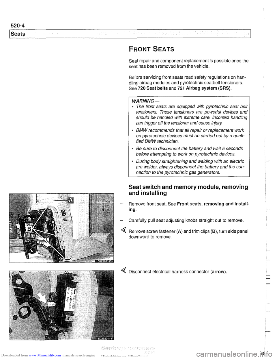
- Carefully pull seat adjusting ltnobs straight out to remove.
Remove screw fastener
(A) and trim clips (B), turn side panel
downward to remove.
Disconnect electrical harness connector
(arrow).
Page 942 of 1002
Downloaded from www.Manualslib.com manuals search engine
- -
Seat Belts
Front seat belt tensioner, removing and
installing
- Disconnect battery negative (-) cable in trunk.
The
front seat belt loclts are equipped with pyrotechnic (ex-
plosive charge) automatic tensioners. These tensioners are
designed to automatically retract and tension the seat belt by
55 mm (approximately 2 inches) in the event of an accident.
CAUTION-
Prior to disconnecting the battery, read the battery discon-
nection cautions given in
001 General Warnings and Cau-
tions.
WARNING-
Pyrotechnic seat belt tensioners are powerful devices and
should be handled with extreme care. Incorrect handling
can trigger the tensioner and cause injury
BMW recommends that all repair or replacement work
on pyrotechnic devices must be carried out by a quali-
fied BMW technician.
Be sure to disconnect the battery and wait
5 seconds
before attempting to work on pyrotechnic devices.
Pyrotechnic devices cannot be repaired. Always re-
place them.
Never treat pyrotechnic components with cleaning
agents or grease.
- Do not expose pyrotechnic components to tempera-
tures above
75% (167°F).
Pyrotechnic components can only be tested electrically
when installedusing the
BMWService Tester (DISplus,
GTI, or MoDiC).
Do not fire a pyrotechnic gas generatorprior to dispos-
al. It must be fired by a special disposal company or
shipped
back to BMW in the packaging of the new com-
ponent.
During body straightening and welding with an electric
arc welder, always disconnect the battery and the con-
nection to the pyrotechnic gas generators.
- Remove front seat as described in 520 Seats.
-
Page 960 of 1002
Downloaded from www.Manualslib.com manuals search engine
721-12
Airbag System (SRS)
Head protection airbag (HPS)
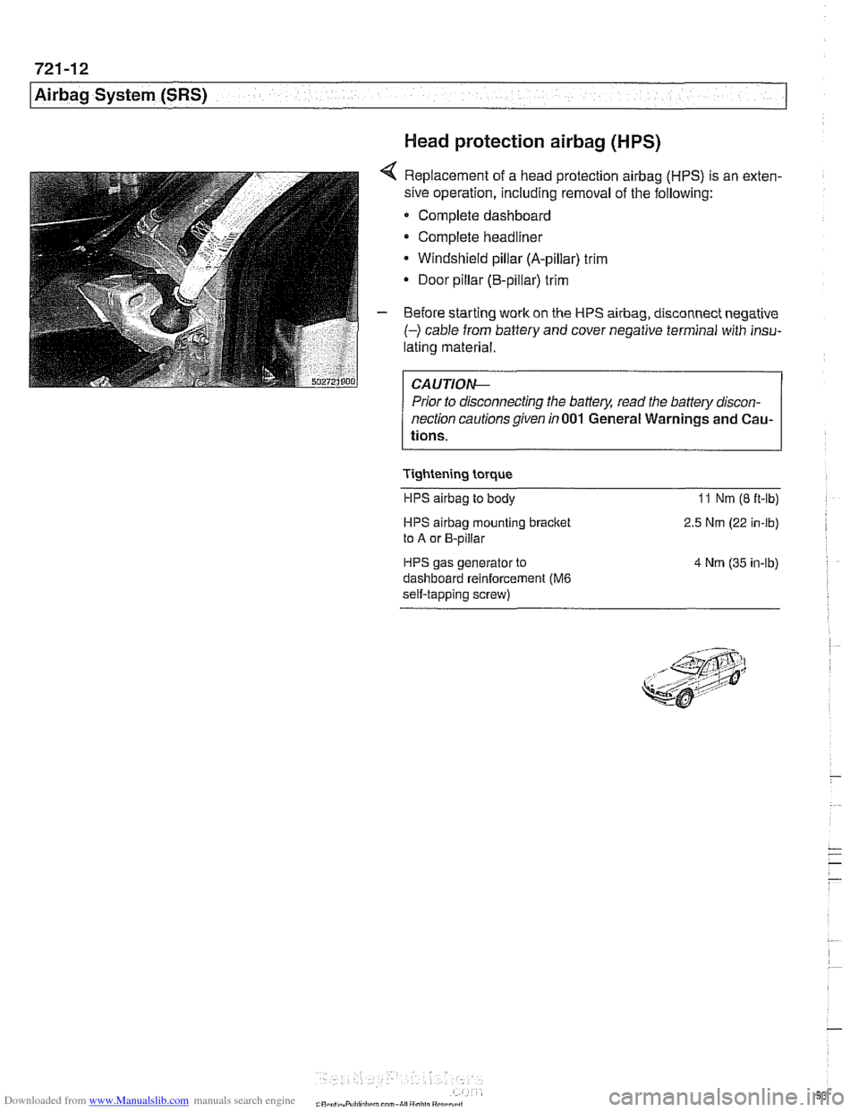
4 Replacement of a head protection airbag (HPS) is an exten-
sive operation, including removal of the following:
Complete dashboard
Complete headliner
Windshield pillar (A-pillar) trim
Door pillar (B-pillar) trim
- Before starting work on the HPS airbag, disconnect negative
(-) cable from battery and cover negative terminal with insu-
lating material.
Prior to disconnecting the battery, read the battery discon-
nection cautionsgiven in001 General Warnings and Cau-
tions.
Tightening torque HPS
airbag to body 11 Nm (8 ft-lb)
HPS airbag mounting bracket
to A or B-pillar
HPS gas generator to
dashboard reinforcement
(M6
self-tapping screw) 2.5
Nm (22 in-lb)
4 Nm (35 in-lb)
Page 992 of 1002
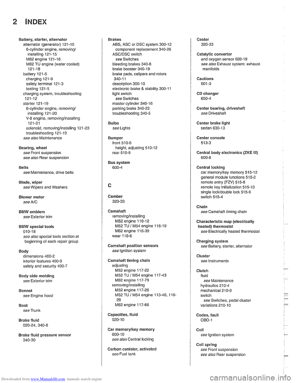
Downloaded from www.Manualslib.com manuals search engine
2 INDEX
Battery, starter, alternator
alternator (generator)
121-10
6-cylinder engine, removingi
installing 121-15
M62 engine 121-16
M62 TU engine (water cooled)
121-18
battery
121-5 charging 121-9
safety terminal 121-3
testing 121-5 charging system, troubleshooting
121-12
starter
121-1 9
6-cylinder engine, removingi instaliinq 121-20 . V-8 engine, rernovinglinsialiing
121-21
solenoid, removinglinstalling
121-23 troubleshooting 121-19
see also Maintenance
Bearing, wheel
see Front suspension
see also Rear suspension
Belts see Maintenance, drive belts
Blade, wiper
see Wipers and Washers
Blower motor see
A/C
BMW emblem
see Exterior trim
BMW special tools 010-18 see also special tools section at
beginning
of each repair group
Body dimensions 400-2
interior features
400-9 salety and security 400-7
Body side molding
see Exterior trim
Bonnet see Engine hood
Boot see Trunk
Brake fluid
020-24, 340-8
Brake fluid pressure sensor
340-30
Brakes
ABS, ASC or DSC system
300-12
component replacement 340-26
ASCIDSC switch
see Switches
bleeding
bralces 340-8
brake booster 340-1 9 bralce Dads. caiioers and rotors ,., 340-1 1
descriotion 300-10
e~ectrdnic brake & stability 300-11
light switch
see Switches
master cylinder
340-16 pariking brake 340-22
troubleshooting 340-5
Bulbs see Lights
Bumper
lront 510-6 height, adjusting 510-12
rear 510-9
Bus system
600-4
Camber
320-33
Camshaft
removingiinslaiiing
M52 engine 116-12
M52 TU
/ M54 engine 116-1 9 M62 engine 11 6-39
wear
116-6
Camshaft position sensors
see ignition system
Camshaft timing chain
adjusting M52 engine
117-22
M52 TU I M54 engine 117-43
M62 engine 117-79 removinglinstalling
M52 engine 117-26
M52TU 1 M54 engine 113-46.116-
28
M62 engine 117-66
Capacities, fluid
020.10
Car rnemorvlicev memorv . . 600-10
see also Centrai
lociking
Carbon canister, activated
see Fuel
tank
Caster
320-33
Catalytic converter and oxygen sensor 020-19
see also Exhaust system: exhaust
manilolds
Cautions
001-3
CD changer
650-4
Center bearing, driveshaft
see Driveshait
Center brake light
sedan
630-13
Center console
513-3
Centrai body electronics (ZKE 111)
600-6
Central locking
car memoryiey memory 515.12 general module iunctions 515-2
remote entry (FZV) 515-8
remote lkey initialization 515-10 single lociddouble ioclk 515-6
switch 515-4
Chain
see Camshaft liming chain
Characteristic map (electrically heated) thermostat
see Electrically heated thermostat
Charging system
see Battery, starter, alternator
Cluster see instruments
Clutch fluid see Maintenance
hydraulics
210-4
mechanical 210-9
switch
see Switches, pedal ciuster
variations
210.10
Codes, fault OED-1
Coil
see Ignition system
Coil spring
see Front suspension
see also Rear
suspe nsion