check engine light BMW 540i 1998 E39 Owner's Manual
[x] Cancel search | Manufacturer: BMW, Model Year: 1998, Model line: 540i, Model: BMW 540i 1998 E39Pages: 1002
Page 374 of 1002
Downloaded from www.Manualslib.com manuals search engine
121-8
/Battery, Starter, Alternator
NOTE-
Automatic transmission cars: ambershifier LED willgo out at
consumer cut-off.
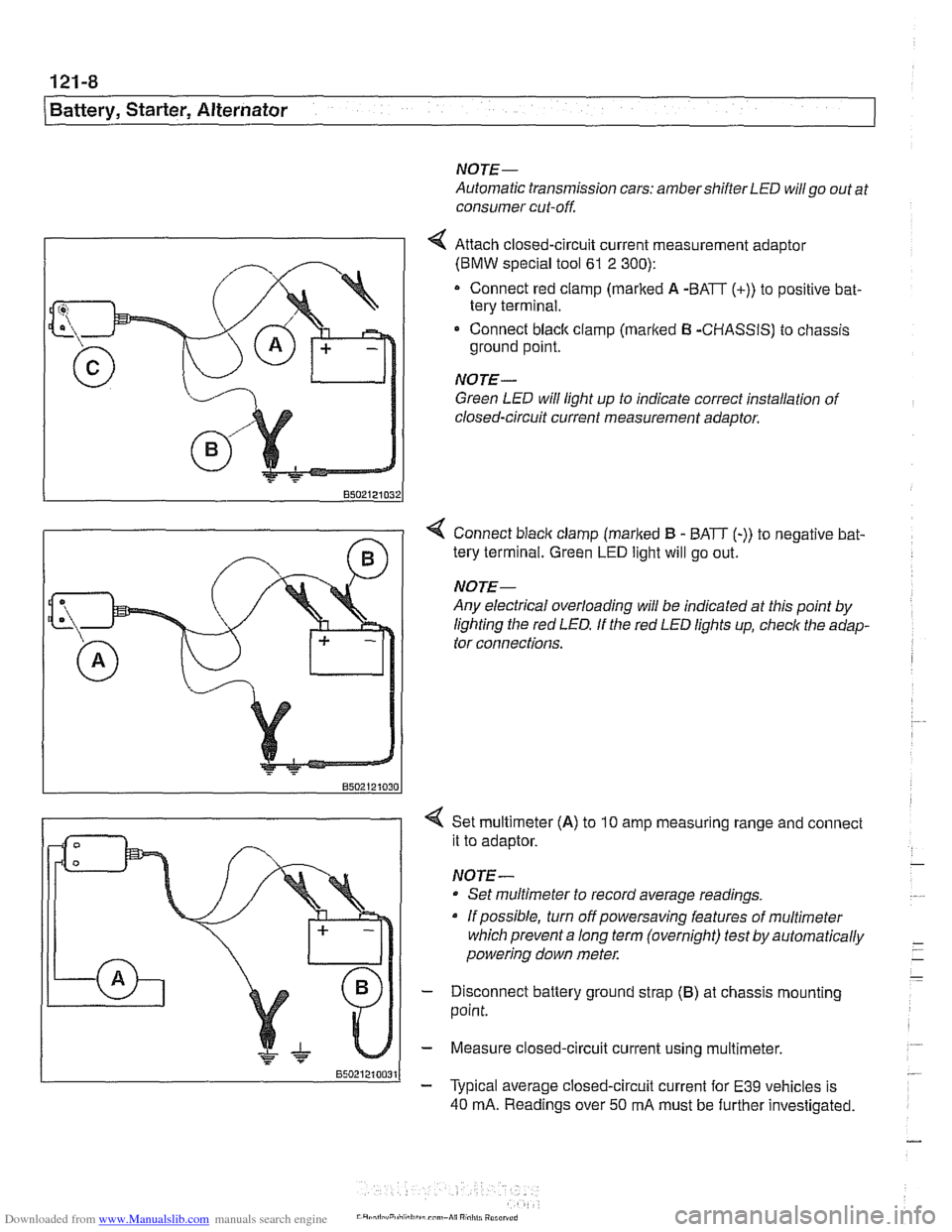
4 Attach closed-circuit current measurement adaptor
(BMW special tool
61 2 300):
Connect red clamp (marked A -BATT (+)) to positive bat-
tery terminal.
Connect
black clamp (marked B -CHASSIS) to chassis
ground point.
NOTE-
Green LED will light up to indicate correct installation of
closed-circuit current measurement
adaotor.
< Connect blaclc clamp (marked B - BATT (-)) to negative bat-
tery terminal. Green
LED light will go out.
NOTE-
Any electrical overloading will be indicated at this point by
lighting the red
LED. If the red LED lights up, check the adap-
tor connections.
< Set multimeter (A) to 10 amp measuring range and connect
it to adaptor.
NOTE -
Set multimeter to record average readings.
Ifpossible, turn offpowersaving features of multimeter
which prevent a long term (overnight) test by automatically
powering down
meter.
- Disconnect battery ground strap (B) at chassis mounting
point.
- Measure closed-circuit current using multimeter.
- Typical average closed-circuit current for E39 vehicles is
40 mA. Readings over 50 mA must be further investigated.
Page 378 of 1002
Downloaded from www.Manualslib.com manuals search engine
Battery, Starter, Alternator
Water-cooled alternator
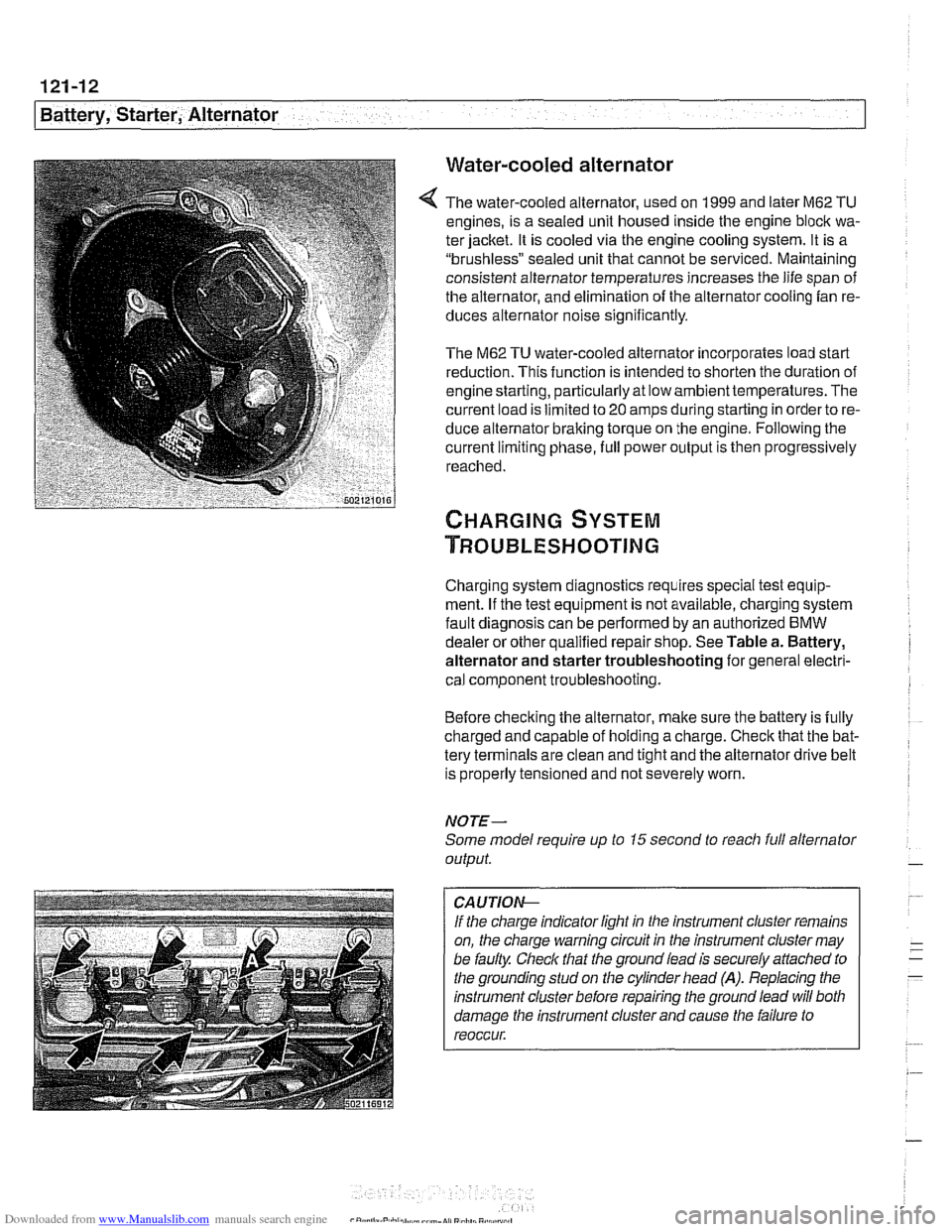
The water-cooled alternator, used on 1999 and later M62 TU
engines, is a sealed unit housed inside the engine block wa-
ter jacket. It is cooled via the engine cooling system. It is a
"brushless" sealed unit that cannot be serviced. Maintaining
consistent alternator temperatures increases the life span of
the alternator, and elimination of the alternator cooling fan re-
duces alternator noise
significantly.
The M62 TU water-cooled alternator incorporates load start
reduction. This function is intended to shorten the duration of
engine starting, particularly at low ambienttemperatures. The
current load is limited to
20 amps during starting in order to re-
duce alternator braking torque on the engine. Following the
current limiting phase, full power output is then progressively
reached.
Charging system diagnostics requires special test equip-
ment. If the test equipment is not available, charging system
fault diagnosis can be performed by an authorized
BMW
dealer or other qualified repair shop. See Table a. Battery,
alternator and starter troubleshooting for general electri-
cal component troubleshooting.
Before checking the alternator, make sure the battery is fully
charged and capable of holding a charge. Check that the bat-
tery terminals are clean and tight and the alternator drive belt
is properly tensioned and not severely worn.
NOTE-
Some model require up to 15 second to reacli full alternator
output.
CA UTIOG
If the charge indicator light in the instrument cluster remains
on, the charge warning circuit in the instrument cluster may
be faulty. Check that the ground lead is securely
affached to
the grounding stud on the cylinder head
(A). Replacing the
instrument cluster before repairing the ground lead will both
damage the instrument cluster and cause the failure to
reoccur.
Page 379 of 1002
Downloaded from www.Manualslib.com manuals search engine
Battery, Starter, ~lternatorl
Charging system quick-check
Use a digital multimeter to measure voltage across the bat-
tery terminals with key off and then again with engine running.
Battery voltage should be about 12.6 volts with key off and be-
tween 13.5 and 14.5 volts with engine running.
NOTE-
The regulated voltage (engine running) should be between
13.2 and 14.5, depending on temperature andoperating con-
ditions.
If the voltage is higher than 14.8, the voltage regula-
tor or
mulitfunction controller is most likely faulty
Check for clean and tight battery cables. Check ground cable
running from negative
(-) battery terminal to chassis and
ground cable running from engine to chassis. Check alterna-
tor drive belt condition and tension.
Charging system, checking
CAUTIOI\C
* Do not disconnect the battery while the engine is running.
Damage to the alternator and/or engine electronic systems
may result.
Only use a digital multimeter when testing charging
system components.
--7
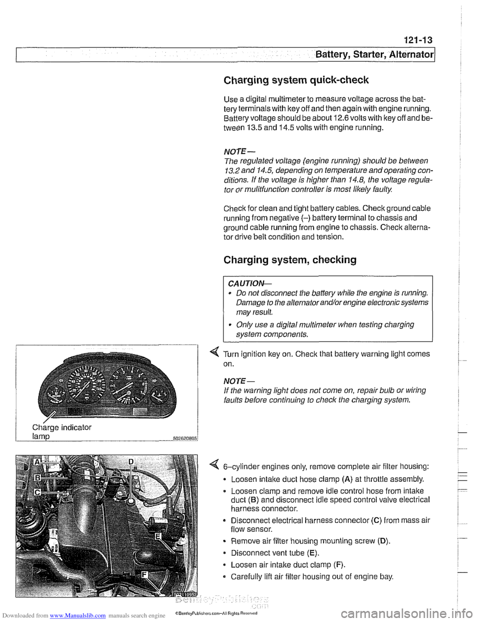
4 Turn ignition key on. Check that battery warning light comes
on.
NOTE-
If the warning light does not come on, repair bulb or wiring
faults before continuing to checlc the charging system.
/ Charge indicator
502820805
4 6-cylinder engines only, remove complete air filter housing:
Loosen
intake duct hose clamp (A) at throttle assembly.
Loosen clamp and remove idle control hose from intake
duct
(B) and disconnect idle speed control valve electrical
harness connector.
Disconnect electrical harness connector
(C) from mass air
flow sensor.
Remove air filter housing mounting screw
(D).
Disconnect vent tube (E).
Loosen air intake duct clamp (F).
Carefully lift air filter housing out of engine bay.
Page 380 of 1002
Downloaded from www.Manualslib.com manuals search engine
- -
/Battery, Starter, Alternator -- - -. - --I
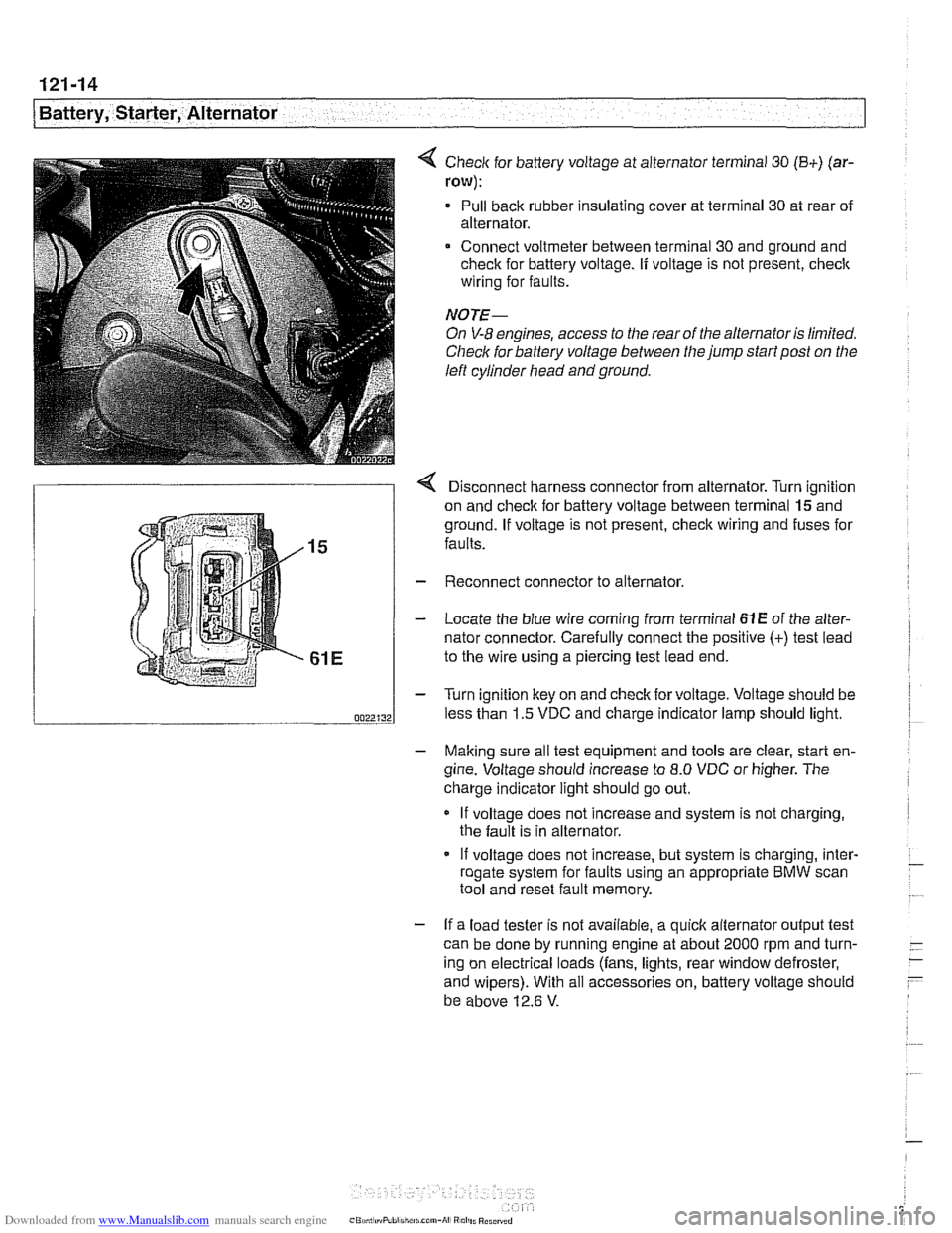
< Check for battery voltage at alternator terminal 30 (B+) (ar-
row):
Pull back rubber insulating cover at terminal 30 at rear of
alternator.
Connect voltmeter between terminal 30 and ground and
check for battery voltage.
If voltage is not present, check
wiring for faults.
NOTE-
On V-8 engines, access to the rear of the alternator is limited.
Check for battery voltage between the jump start post on the
left cylinder head and ground.
r Disconnect harness connector from alternator. Turn ianition
on and check for battery voltage between terminal
lgand
ground. If voltage is not present, check wiring and fuses for
faults.
Reconnect connector to alternator.
Locate the blue wire coming from terminal
61E of the alter-
nator connector. Carefully connect the positive
(+) test lead
to the wire using a piercing test lead end.
Turn ignition key on and check for voltage. Voltage should be
less than 1.5 VDC and charge indicator lamp should light.
- Making sure all test equipment and tools are clear, start en-
gine. Voltage should increase to
8.0 VDC or higher. The
charge indicator light should go out.
If voltage does not increase and system is not charging,
the fault is in alternator.
- If voltage does not increase, but system is charging, inter- - roaate svstem for faults usina an appropriate BMW scan - .. . tool and'reset fault memory.
- If a load tester is not available, a quick alternator output test
can be done by running engine at about 2000 rpm and turn-
- -
ing on electrical loads (fans, lights, rear window defroster, -
- and wipers). With all accessories on, battery voltage should
be above 12.6
V.
Page 395 of 1002
Downloaded from www.Manualslib.com manuals search engine
Fuel Injection
Warnings and cautions
For personal safety, as well as the protection of sensitive
electronic components, adhere to the warnings and cautions
on the following pages.
WARNING-
Gasoline is highly flammable and its vapors are explosive.
Do not smoke or work on a car near heaters or other fire
hazards when diagnosing and repairing fuel system prob-
lems. Have a fire extinguisher available in case of an emer-
gency
Renew fuel system hoses, clamps and O-rings any
time they are removed.
When working on an open fuel system, wear suitable
hand protection, as prolonged contact
with fuel can
cause illnesses and skin disorders.
* The ignition system produces high voltages that can be
fatal. Avoid contact with exposed terminals. Use ex-
treme caution when
working on a car with the ignition
switched on or the engine running.
CAUTION-
- Disconnecting the battery may erase fault code($ storedin
memory Check for fault codes prior to disconnecting the
battery cables. Read the battery disconnection cautions in
001 General Warnings and Cautions.
a Connect and disconnect the DME system wiring and
1 test equipment leads only when the ignition is switched
off.
Wait at least 1 minute after turning off the ignition be-
fore removing the engine control module (ECM) con-
nector. If the connector is removed before this time,
residualpower in the system relay may damage the
control module.
Fuel system cleaners and other chemical additives oth-
er than those specifically recommended by BMW may
damage the catalytic converter, the oxygen sensor or
other fuel supply components.
* Do not connect any test equipment that delivers a 12-
volt power supply to terminal 15 (+) of the ignition coil.
The current flow may damage the ECM. In general,
connect test equipment only as specified by BMW or
the equipment maker.
Only use a digital
multirneter for electrical tests. Only
use an LED test light for
quiclc tests.
Page 403 of 1002
Downloaded from www.Manualslib.com manuals search engine
130-1 3
Fuel Injection I
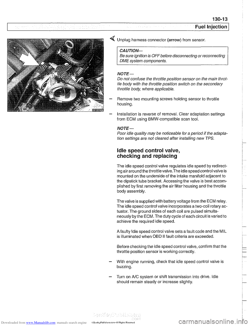
< Unplug harness connector (arrow) from sensor.
CAUTION-
Be sure ignition is OFF before disconnecting or reconnecting
DME system components.
NOTE-
Do not confuse the throttle position sensor on the main Nirot-
tle body with the throttle position switch on the secondary
throttle body, where applicable.
- Remove two mounting screws holding sensor to throttle
housing.
- Installation is reverse of removal. Clear adaptation settings
from ECM using BMW-compatible scan tool.
NOTE-
Poor idle quality may be noticeable for a period if the adapta-
tion settings are not cleared after installing new TPS.
ldle speed control valve,
checking and replacing
The idle speed control valve regulates idle speed by redirect-
inq airaround the throttlevalve.The idlespeed control valve is
mounted on the underside of the intake manifold adjacent to
the dipstick tube bracket. Accessing the valve is best accom-
plished by first removing the air filter housing and the throttle
body assembly.
The valve issupplied with
batteryvoltagefrom the ECM relay.
The idle speed control valve incorporates a two-coil rotary ac-
tuator. The ground sides of each coil are pulsed
sirnulta-
neously by the ECM. The duty cycle of each circuit is varied to
achieve the required idle speed.
Afaulty ldle speed control valve sets afault code and the MIL
is illuminated when
OED II fault criteria are exceeded.
Before checking the idle speed control valve, confirm that the
throttle position sensor is working correctly.
- With engine running, check that idle speed control valve is
buzzing.
- Turn on AIC system or shift transmission into drive. ldle
should remain steady or increase slightly.
Page 428 of 1002
Downloaded from www.Manualslib.com manuals search engine
130-38
Fuel Injection
Throttle cable, adjusting
(MS 42.0)
The throttle assembly on MS 42.0 cars uses a throttle cable.
The cable should be adjusted any time it is disconnected or
replaced. This procedure requires the factory scan tool or an
equivalent to read and adjust throttle angle. It is recommend-
ed the procedure be done by an authorized
BMW dealer ser-
vice department
Basic adjustment:
Ensure that at idle (accelerator pedal in rest position) throt-
tle cable has detectable play at throttle lever attaching
point. Play must not exceed maximum allowable.
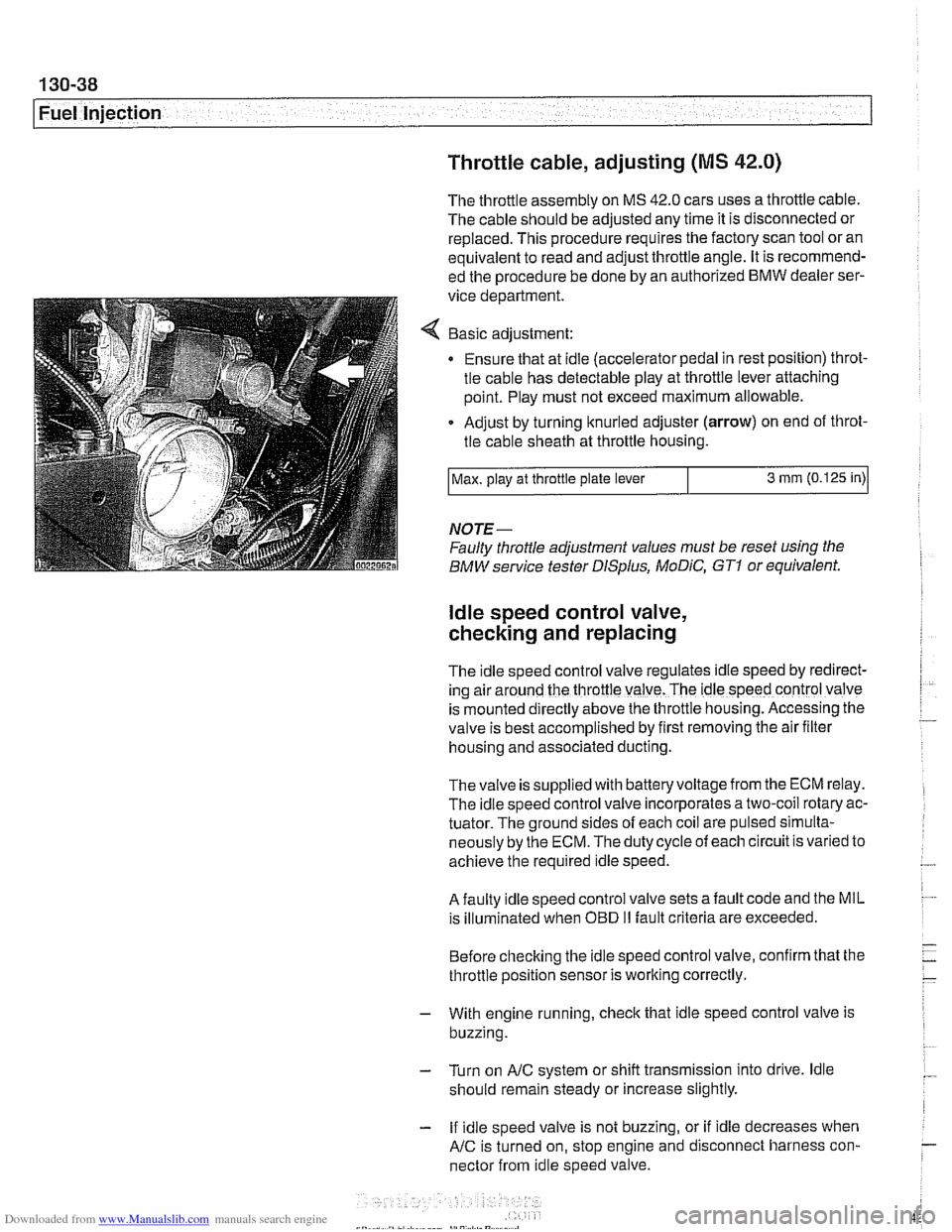
Adjust by turning knurled adjuster
(arrow) on end of throt-
tle cable sheath at throttle housing.
NOTE-
Faulty throttle adjustment values must be reset using the
BMW service tester
DISplus, MoDiC, GTI or equivalent.
Max.
play at throttle plate lever
ldle speed control valve,
checking and replacing
3 mm (0.125 in)
The Idle speed control valve regulates Idle speed by red~rect-
ing air around the throttle valve. The ldle speed control valve
is mounted
d~rectly above the throttle housing. Accessing the
valve is best accomplished by
flrst removing the air fllter
housing and associated ducting.
Thevalve is supplied with batteryvoltage from the ECM relay.
The idle speed control valve incorporates a two-coil rotary ac-
tuator. The ground sides of each coil are pulsed simulta-
neously by the ECM. The duty cycle of each circuit is varied to
achieve the required idle speed.
A faulty idle speed control valve sets a fault code and the MIL
is illuminated when
OED II fault criteria are exceeded.
Before checking the idle speed control valve, confirm that the
throttle position sensor is working correctly.
- With engine running, check that idle speed control valve is
buzzing.
- Turn on AIC system or shift transmission into drive. ldle
should remain steady or increase slightly.
- If idle speed valve is not buzzing, or if idle decreases when
AIC is turned on, stop engine and disconnect harness con-
nector from idle speed valve.
Page 442 of 1002
Downloaded from www.Manualslib.com manuals search engine
.. .-
/Fuel lnjeciion
NOJE-
With engine oft disconnect harness connector and checlc
heating element resistance between white wires on the sen-
sor side of harness. If the element is electrically open (no
continuity), replace sensor.
- If oxygen sensor does not produce a fluctuating voltage and
preheater circuit is
OK, replace sensor.
NOJE-
If not already applied, coat oxygen sensor threads w~th anti-
seize compound before installat~on. Do not get the com-
pound on the sensor tip.
Tightening torque Oxygen sensor to exhaust system
55 Nm (41 ft-lb)
Fuel injectors, checking and replacing
The fuel iniectors are switched on and off (oaened and
closed)
by'the ECM. The injectors are connkcted to acom-
mon power source. A ground signal from the ECM is used to
open and close the injectors.
CA U JIOG
Use only a digital multimeter or an LED injector tester when
testing injectors or wiring. Use of an analog
VOM or incan-
descent test light may damaqe the engine controlmodule.
4 Remove fuel rail cover. See 110 Engine Removal and in-
stallation.
With the engine running, place the point of a long screwdriver
on each injector and check for a cliclting vibration.
If no vibra-
tion is found do the voltage
checit shown below.
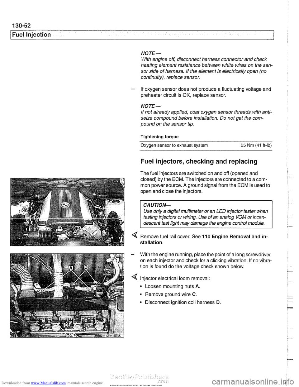
Injector electrical loom removal:
- Loosen mounting nuts A.
Remove ground wire C.
Disconnect ignition coil harness D
Page 443 of 1002
Downloaded from www.Manualslib.com manuals search engine
Fuel Injection I
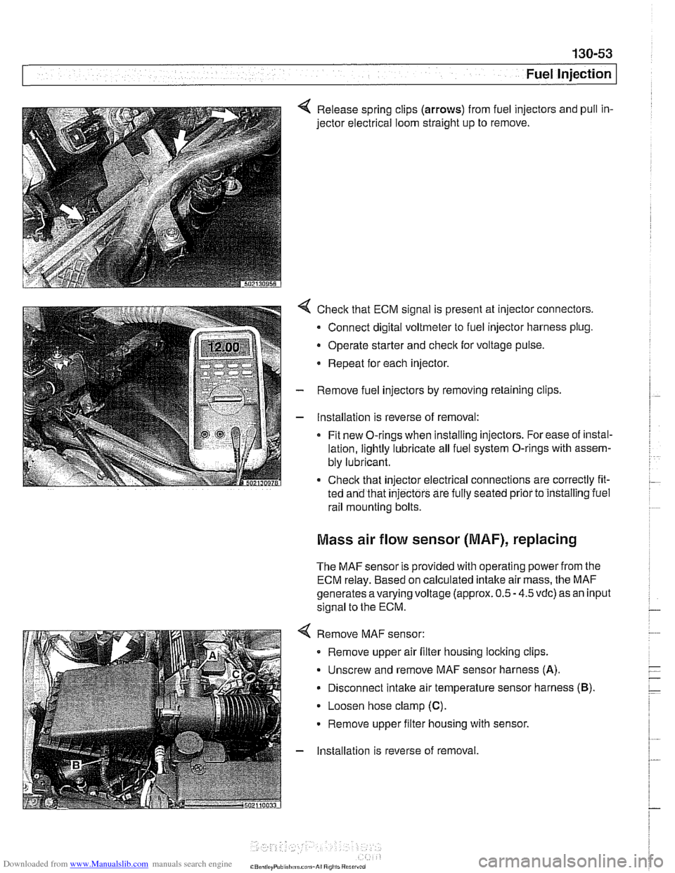
4 Release spring clips (arrows) from fuel injectors and pull in-
jector electrical loom straight up to remove.
4 Check that ECM signal is present at injector connectors.
- Connect digital voltmeter to fuel injector harness plug.
Operate starter and
check for voltage pulse.
* Repeat for each injector.
- Remove fuel injectors by removing retaining clips
- Installation is reverse of removal:
Fit new O-rings when installing injectors. For ease of instal-
lation, lightly lubricate all fuel system O-rings with assem-
bly lubricant.
Check that injector electrical connections are correctly fit-
ted and that
injectors are fully seated prior to installing iuel
rail mounting bolts.
Mass air flow sensor (MAF), replacing
The MAF sensor is provided with operating power from the
ECM relay. Based on calculated intake air mass, the MAF
generates
avarying voltage (approx. 0.5 - 4.5 vdc) as an input
signal to the ECM.
4 Remove MAF sensor:
Remove upper air filter housing locking clips.
Unscrew and remove MAF sensor harness
(A).
Disconnect intake air temperature sensor harness (B).
Loosen hose clamp (C).
Remove upper filter housing with sensor.
- Installation is reverse of removal
Page 444 of 1002
Downloaded from www.Manualslib.com manuals search engine
130-54
I Fuel Injection ldle speed control valve,
testing and replacing
ldle speed is maintained by the ECM through the idle speed
control valve. The idle control function compensates for en-
gine load and engine operating conditions. ldle speed is
adaptive through the ECM and no adjustments can be made.
Before checking valve, confirm that throttle position sensor is
working correctly.
NOTE-
The test given below is an electrical check only. It does not
check the mechanical operation of the valve. If the valve is
sticking, hanging up or is sluggish in operation, substituting a
Inown good valve is the best way to check it.
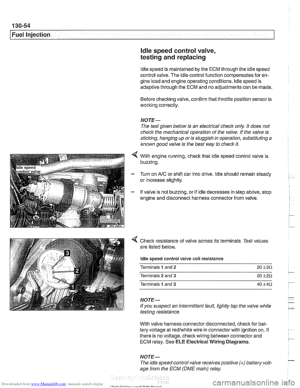
With engine running, check that idle speed control valve is
buzzing.
Turn on
AIC or shift car into drive. ldle should remain steady
or increase slightly.
If valve is not buzzing, or if idle decreases in step above, stop
engine and disconnect harness connector from valve.
4 Check resistance of valve across its terminals. Test values
are listed below.
ldle speed control valve coil resistance
Terminals
1 and 2 20 +2%
Terminals 2 and 3 20 +2Q
Terminals 1 and 3 40 +4%
NOTE-
If you suspect an intermittent fault, lightly tap the valve while
testing resistance.
With valve harness connector disconnected, check for bat-
tery voltage at redlwhite wire in connector with ignition on.
If . ~~ ~~
there is no voltage, check wiring between connector and 7 ECM relay. See ELE Electrical Wiring Diagrams.
NOTE- - The idle speed control valve receivespositive (+) battery volt-
age from the ECM (DME main) relay