fuel pressure BMW 540i 1998 E39 Owner's Manual
[x] Cancel search | Manufacturer: BMW, Model Year: 1998, Model line: 540i, Model: BMW 540i 1998 E39Pages: 1002
Page 423 of 1002
Downloaded from www.Manualslib.com manuals search engine
Fuel lniection I
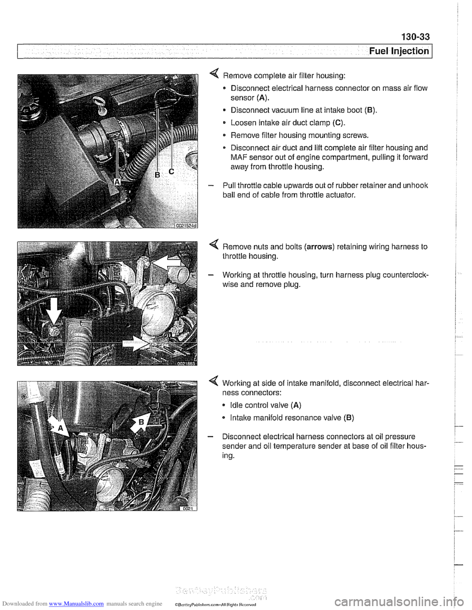
4 Remove complete air filter housing:
Disconnect electrical harness connector on mass air flow
sensor
(A).
Disconnect vacuum line at intake boot (B).
Loosen Intake air duct clamp (C).
Remove filter housing mounting screws
Disconnect air duct and
lift complete air filter housing and
MAF sensor out of engine compartment, pulling it forward
away from throttle housing.
- Pull throttle cable upwards out of rubber retainer and unhoolc
ball end of cable from throttle actuator.
4 Remove nuts and bolts (arrows) retaining wiring harness to
throttle housing.
- Working at throttle housing, turn harness plug counterclock-
wise and remove plug.
4 Working at side of intake manifold, disconnect electrical har-
ness connectors:
Idle control valve (A)
lntalce manifold resonance valve (B)
- Disconnect electrical harness connectors at oil pressure
sender and oil temperature sender at base of oil filter hous-
ing.
CO,l,> ti,, "F"bl,rl,irrm.,-AI ",",>ti
Page 426 of 1002
Downloaded from www.Manualslib.com manuals search engine
130-36
[~uel Injection
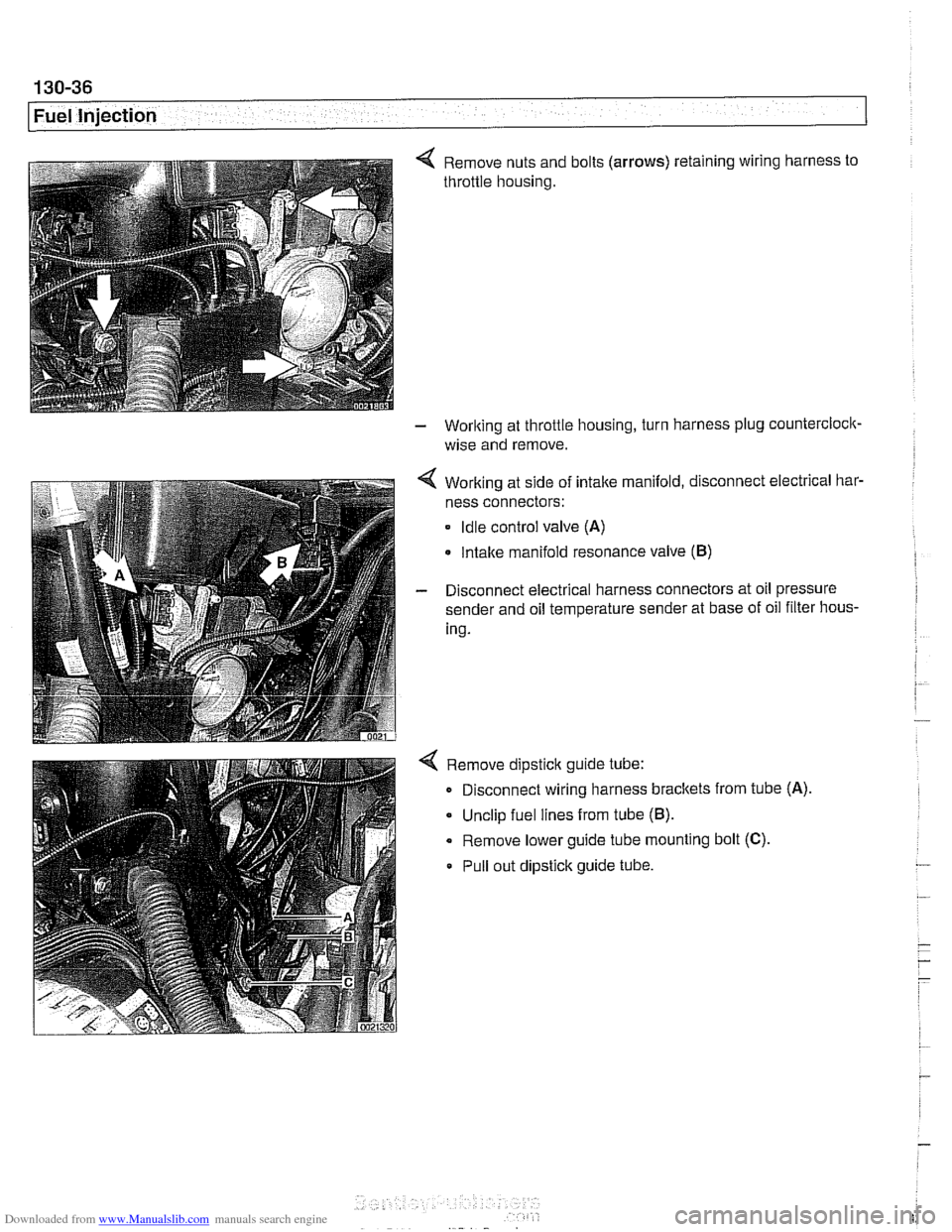
4 Remove nuts and bolts (arrows) retaining wiring harness to
throttle housing.
- Working at throttle housing, turn harness plug countercloclc
wise and remove.
4 Working at side of intake manifold, disconnect electrical bar-
ness connectors:
Idle control valve (A)
Intake manifold resonance valve (B)
- Disconnect electrical harness connectors at oil pressure
sender and oil temperature sender at base of oil filter hous-
ing.
4 Remove dipstick guide tube:
Disconnect wiring harness brackets from tube
(A)
Unclip fuel lines from tube (B).
Remove lower guide tube mounting bolt (C).
Pull out dipstick guide tube.
Page 429 of 1002
Downloaded from www.Manualslib.com manuals search engine
. .
Fuel Injection
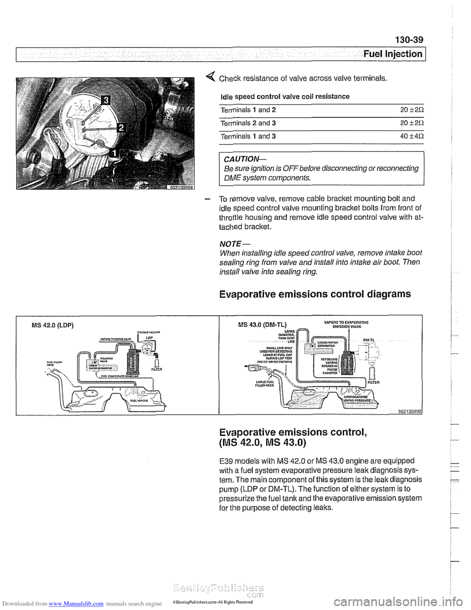
Check resistance of valve across valve terminals
Idle speed control valve coil resistance
Terminals
1 and 2 20 i2.0.
Terminals 2 and 3 20 i2.0.
Terminals 1 and 3 40 i4.0.
CAUTIOIG
Be sure ignition is OFFbefore disconnecting or reconnecting
DME system components.
- To remove valve, remove cable bracket mounting bolt and
idle speed control valve mounting bracket bolts from front of
throttle housing and remove idle speed control valve with at-
tached bracket.
NOTE-
When installing idle speed control valve, remove intake boot
sealing ring from valve and install into intake air boot. Then
install valve info sealing
ring.
Evaporative emissions control diagrams
MS 42.0 (LDP) ,-a"-
Evaporative emissions control,
(MS 42.0, MS 43.0)
E39 models with MS 42.0 or MS 43.0 engine are equipped
with a fuel system evaporative pressure leak diagnosis sys-
tem. The main component of this system is the leak diagnosis
pump (LDP or DM-TL). The function of either system is to
pressurize the fuel tank and the evaporative emission system
for the purpose of detecting leaks.
Page 433 of 1002
![BMW 540i 1998 E39 Owners Manual Downloaded from www.Manualslib.com manuals search engine
130-43
Fuel Injection ]
I I I
12 llnput IFeedback signal, engine start /Starter
Table c. Siemens MS 42.0 and MS 43.0 ECM pin assignments BMW 540i 1998 E39 Owners Manual Downloaded from www.Manualslib.com manuals search engine
130-43
Fuel Injection ]
I I I
12 llnput IFeedback signal, engine start /Starter
Table c. Siemens MS 42.0 and MS 43.0 ECM pin assignments](/img/1/2822/w960_2822-432.png)
Downloaded from www.Manualslib.com manuals search engine
130-43
Fuel Injection ]
I I I
12 llnput IFeedback signal, engine start /Starter
Table c. Siemens MS 42.0 and MS 43.0 ECM pin assignments (continued)
I I - I
13 Input /I Alternator (generator) Notes
Throttle
valve
Crankshaft position sensor
Throttle valve (MS
42.0)
Throttle valve
Pin
6
7
8
9
10
11
14
15
16
17
18
19
20
I 1- I
23 l~round I~round, intaite air temperature sensor /Intake air temperature sensor
Signal
Output
Input
Input
Input
I I I
Component/function
Not used
Throttle valve supply potentiometer
2
Signal, crankshaft position sensor
Signal,
pedal position sensor 2 (MS 42.0)
Signal, throttle position sensor 1
Not used
Ground
Ground
Input
Ground
Ground
Input
Ground Cranltshaft position sensor
21
24
25
26
27
28
29
30
I 1- I
33 1 input ISignal, cylinder 1 fuel injector /cylinder 1 fuel injector
Ground, throttle position sensor (MS
42.0)
Ground, exhaust camshaftsensor I
Signal, pedal position sensor 1 (MS 42.0)
Ground, mass air flow sensor
Ground, intake camshaft sensor
1
Signal, throttle potentiometer 1
Ground, throttle position sensor
22 loutput I~ignal, intake air temperature Ilntake air temperature sensor
I I - I
Throttle
valve (MS 42.0)
Camshaft position sensor I
Throttle valve (MS
42.0)
Hot film mass air flow sensor
Camshaft position sensor i
Throttle valve
Throttle valve
Ground
Output
Ground Input
Output
Ground
Output
Out~ut
Ground, crankshaft position sensor
Knoclt sensor
31
34
35
36
37
38
39
Signal, coolant temperature sensor
Ground, coolant temperature sensor
Signal,
oil pressure
Signal, engine
oil temperature sensor
Ground, engine oil temperature sensor
Signal, knock sensor
Signal, knock sensor
32 loutput ISignal, ltnock sensor l~nock sensor
40
41
Coolant temperature sensor
Coolant temperature sensor
Oil pressure switch
Oil temperature sensor
Oil temperature sensor
Knoclt sensor
I
Input
input
Input
Input
Input
Inout
Signal, knock sensor
Input
Input Signal, cylinder
2 fuel injector
Signal, cylinder
3 fuel injector
Signal, cylinder
4 fuel injector
Signal, cylinder
5 fuel injector
Signal, cylinder
6 fuel injector
Sianai, oil level sensor Cylinder
2 fuel
injector
Cylinder
3 fuel injector
Cylinder
4 fuel injector
Cylinder
5 fuel injector
Cylinder
6 fuel injector
Oil level sensor
-
Signal. VANOS inlet valve
Signal. VANOS outlet valve VANOS
inlet valve
VANOS outlet valve
Page 434 of 1002
Downloaded from www.Manualslib.com manuals search engine
Fuel Injection
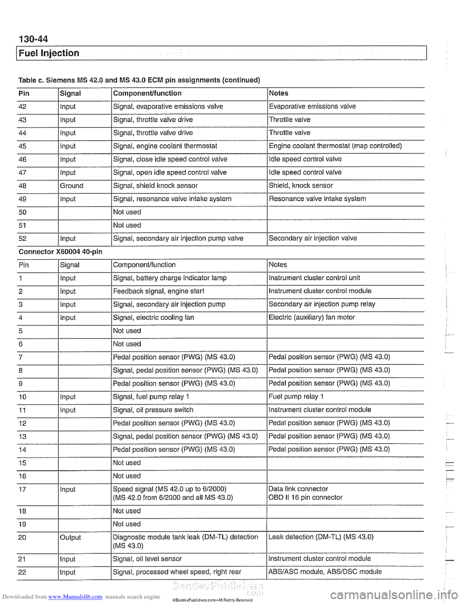
Table c. Siemens MS 42.0 and MS 43.0 ECM pin assignments (continued)
Pin
42
43
44
45
46
47
48
49 50
51
52 Componentlfunction
Signal, evaporative emissions valve
Signal, throttle
valve drive
Signal, throttle valve drive
Signal, engine coolant thermostat
Signal, close idle speed control valve
Signal, open idle speed control valve
Signal, shield
ltnock sensor
Signal, resonance valve
intake system
Not used
Not used
Signal, secondary air injection pump valve
Signal
Input
Input
Input
Input
input
Input
Ground
Input
Input
Notes
Evaporative emissions valve
Throttle valve
Throttle valve Engine coolant thermostat (map controlled)
idle speed control valve
Idle speed control valve
Shield,
knock sensor
Resonance valve intake system
Secondary air injection valve
Connector
X60004 40-pin Notes
instrument cluster control unit
Instrument cluster control module
Secondary air injection pump relay
Electric (auxiliary) fan motor
Pedal position sensor (PWG) (MS 43.0)
Pedal position sensor (PWG) (MS 43.0)
Pedal position sensor (PWG) (MS 43.0)
Fuel pump relay
1
Instrument cluster control module
ComponenVfunction
Signal, battery charge indicator lamp
Feedback signal, engine start
Signal, secondary air injection pump
Signal, electric cooling fan
Not used
Not used
Pedal position sensor (PWG) (MS 43.0)
Signal, pedal position sensor (PWG) (MS 43.0)
Pedal position sensor (PWG) (MS 43.0)
Signal,
fuel pump relay 1
Signal, oil pressure switch
Pin
1
2 3
4
5
6
7
8
9
10
11 Signal
Input
Input
input
input
Input
Input
Page 448 of 1002
Downloaded from www.Manualslib.com manuals search engine
Fuel Injection Evaporative fuel system pressure leak
diagnosis, overview
(M5.2.1 only)
1998 540i models are equipped with an evaporative fuel sys-
tem pressure leak diagnosis system. The main component of
this system is the leak diagnosis pump (LDP). The function of
the LDP is to pressurize the fuel tank and the evaporative
emission system for the purpose of detecting
leaks. This sys-
tem is capable of detecting a leak as small as 0.5 mm.
The LDP, located in the left rear wheel housing, is a unitized
component that contains the following:
Vacuum chamber. Pneumatic pump chamber.
DME activated vacuum solenoid
Reed switch (provides switched voltage
feedback signal to
ECM).
The vacuum supply line is in the wiring harness from the en-
gine compartment and runs down the driver's side of the vehi-
cle.
The canister vent valve is integrated into the LDP, which is
electrically controlled by the ECM. The canister vent valve is
opened to provide fresh air entry into the fuel system only dur-
ing purge operation.
- Purge operation characteristics:
Off idle through full throttle: purge valve opened by pulse
width modulated (PWM) control of the ECM. PWM duty cy-
cle varies by engine operating conditions
(e.g. warm idle,
purge valve opened slightly; cold
idleldecel with engine
temp
< 67" C, purge valve always closed).
Page 458 of 1002
Downloaded from www.Manualslib.com manuals search engine
130-68
Fuel Injection
0
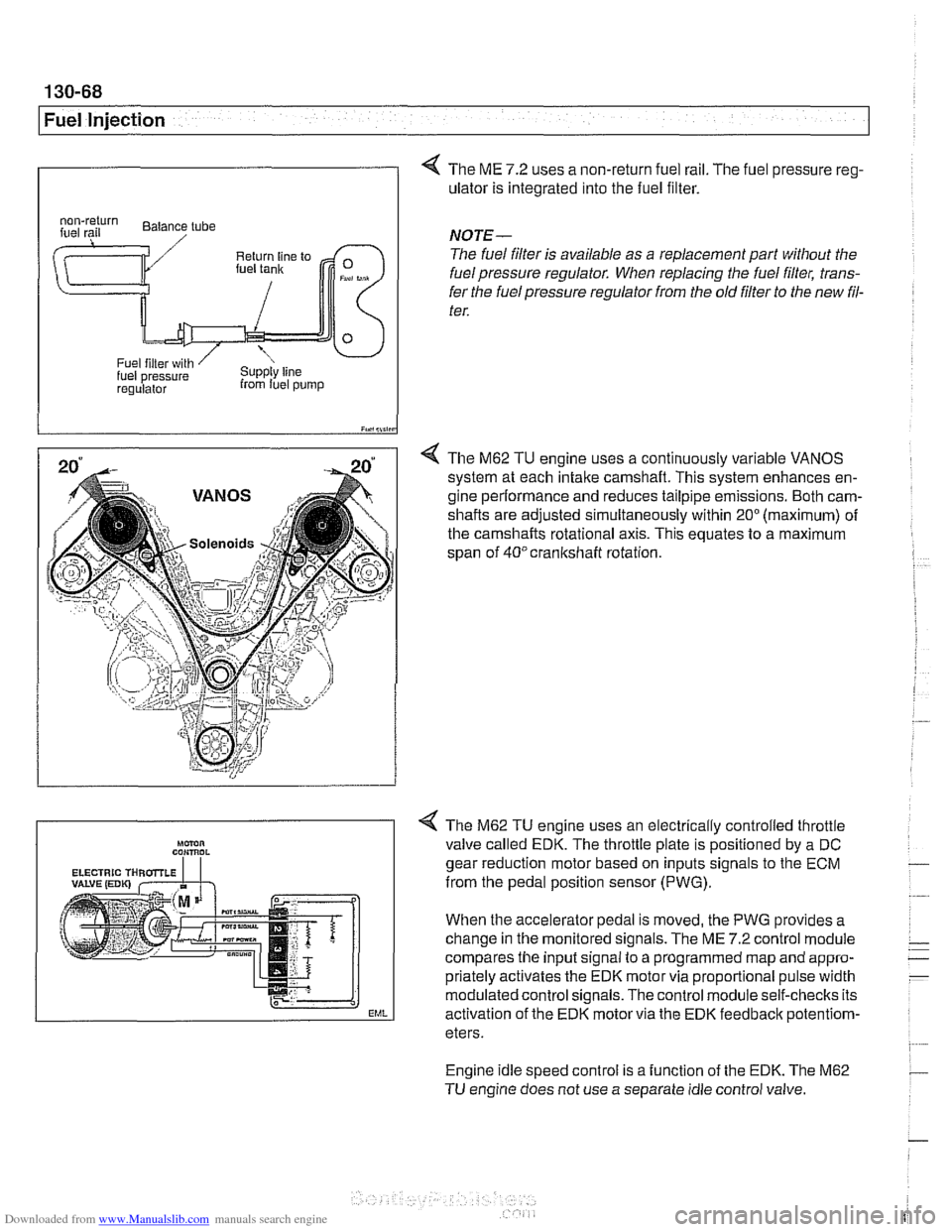
4 The ME 7.2 uses a non-return fuel rail. The fuel pressure reg-
ulator is integrated into the fuel filter.
I iY.,lii,in
4 The M62 TU engine uses a continuously variable VANOS
system at each intake camshaft. This system enhances en-
gine performance and reduces tailpipe emissions. Both cam-
shafts are adjusted simultaneously within
20" (maximum) of
the camshafts rotational axis. This equates to a maximum
span of
40°crankshaft rotation.
regulalor from luel pump
NOTE-
The fuel filter is available as a replacement part without the
fuel pressure regulator. When replacing the fuel filter, trans-
fer the fuel pressure regulator from the old
filter to the new fil-
ter.
Engine idle speed control is a function of the EDK. The M62
TU engine does not use a separate idle control valve.
Mmn CON,ROL
EML
< The M62 TU engine uses an electrically controlled throttle
valve called EDK. The throttle plate is positioned by a DC
gear reduction motor based on inputs signals to the ECM
from the pedal position sensor (PWG).
When the accelerator pedal is moved, the PWG provides a
change in the monitored signals. The ME
7.2 control module
compares the input signal to a programmed map and appro-
priately activates the EDK motor via proportional pulse width
modulated control signals. The control module self-checks its
activation of the EDK motor via the EDK feedbaclc
potentiom-
eters.
Page 463 of 1002
Downloaded from www.Manualslib.com manuals search engine
( Mass Air Flow Sensor
1" Intake air temp. (NTC)
Sensor qround
Reference voltage . . . -., f fitr mass signal I
Fuel Injection I
Release fuel injector locking clips (arrow).
- Remove fuel injector loom boxes and lay to one side.
- Remove 4 fuel rail mounting fasteners.
4 Disconnect fuel line at quick-disconnect. To disconnect,
press in plastic collar (arrow) and separate fuel line.
WARNING -
Fuel may be expelled underpressure. Do not srnol(e or work
near heaters or
other fire hazards. Keep a fire extinguisher
handy. Before disconnecting fuel hoses, wrap a cloth around
fuel hose
to absorb anv leakinq fuel. Plug all open fuel lines.
- Lifl fuel rail and injectors straight up to remove.
- lnstallation is reverse of removal. Use new injector seals and
clamps during installation.
Mass air flow (MAF) sensor,
removing and installing
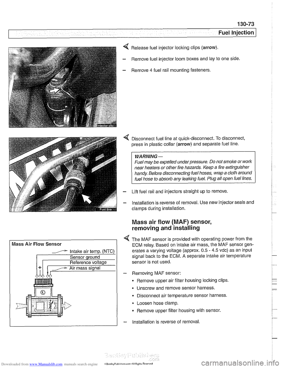
4 The MAF sensor is provided with operating power from the
ECM relay. Based on intake air mass, the MAF sensor gen-
erates a varying voltage (approx. 0.5
- 4.5 vdc) as an input
signal
back to the ECM. A separate intalte air temperature
sensor is not used.
- Removing MAF sensor:
Remove upper air filter housing locking clips
Unscrew and remove sensor harness.
Disconnect air temperature sensor harness.
Loosen hose clamp.
Remove upper filter housing with sensor.
- lnstallation is reverse of removal
Page 464 of 1002
Downloaded from www.Manualslib.com manuals search engine
130-74
I Fuel Injection
Evaporative system pressure leak
diagnosis, overview
The M62 TU engine is equipped wlth an evaporative fuel sys-
tem pressure leak diagnosis system. The main component of
this system is the leakdiagnosis pump (LDP). The function of
the LDP is to pressurize the fuel tank and the evaporative
emission system for the purpose of detecting leaks.
This system iscapable of detecting a
lealcas small as0.5 mm.
The LDP, located in the left rear wheel housing, contains the
following:
Vacuum chamber. Pneumatic pump chamber
DME activated vacuum solenoid
Reed switch (provides switched voltage
feedback signal to
DME).
The vacuum supply line is in the wiring harness from the en-
gine compartment and runs down the driver's side of the vehi-
cle.
The canister vent valve is
~ntegrated into the LDP, which IS
electrically controlled by the ECM. The canister vent valve is
opened to provide fresh air entry into the fuel system only dur-
ing purge operation.
- Purge operation characteristics:
Off idle through full throttle: purge valve opened by pulse
width modulated (PWM) control of the ECM. PWM duty cy-
cle varies by engine operating conditions
(e.g. warm idle,
purge valve opened slightly; cold
idleldecel with engine
temp
< 67" C. purge valve always closed).
Page 469 of 1002
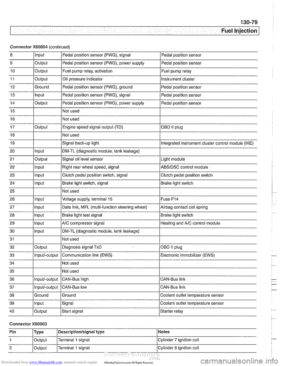
Downloaded from www.Manualslib.com manuals search engine
Fuel Injection I
Connector X60004 (continued)
8 10
11
12
13
14
15
16
9
Output 0
Input
17
18
19
20
21
22
23
24
25
26
27
28
29
30
31
32
33
34
35
36
39
llnput lsignal l~oolant outlet temperature sensor
Output
Output
Ground
Input
Output
I I - I
40 /output Istart signal Istarter relay
Pedal position sensor (PWG), signal
Output Input
Output
input
Input
Input
Input
Input
Input
input
Input
Output
Input/-output
Input/-output
37
Connector X60003
Pedal position sensor
Fuel pump relay, activation
Oil pressure indicator Pedal position sensor (PWG), ground
Pedal position sensor (PWG), signal
Pedal position sensor (PWG), power supply
Not used
Not used Fuel
pump relay
Instrument cluster
Pedal position sensor
Pedal position sensor
Pedal position sensor
Engine speed signal output (TD)
Not used
Signal
back-up light
DM-TL (diagnostic module,
tank leakage)
Signal oil level sensor
Right rear wheel speed, signal
Clutch pedal position switch, signal
Brake light switch, signal
Not used
Voltage supply, terminal
15
Data link, MFL (multi-function steering wheel)
Brake light test signal
AJC compressor signal
DM-TL (diagnostic module, tank
leakage)
Not used
Diagnosis signal
TxD
Communication link (EWS)
Not used
Not used
CAN-BUS hiqh
38 1 Ground l~round I Coolant outlet temperature sensor
OED II plug
Integrated instrument cluster control module (IKE)
Light module
ABSIDSC control module
Clutch pedal position switch
Brake light switch
Fuse
F14
Airbag contact coil spring
Brake light switch
Heating and
A/C control module
OBD
II plug
Electronic immobilizer (EWS)
CAN-Bus link
CAN-Bus link
Input/-output CAN-Bus low