key BMW 540i 1998 E39 Owner's Manual
[x] Cancel search | Manufacturer: BMW, Model Year: 1998, Model line: 540i, Model: BMW 540i 1998 E39Pages: 1002
Page 672 of 1002
Downloaded from www.Manualslib.com manuals search engine
320-1 4
Steering and Wheel Alignment
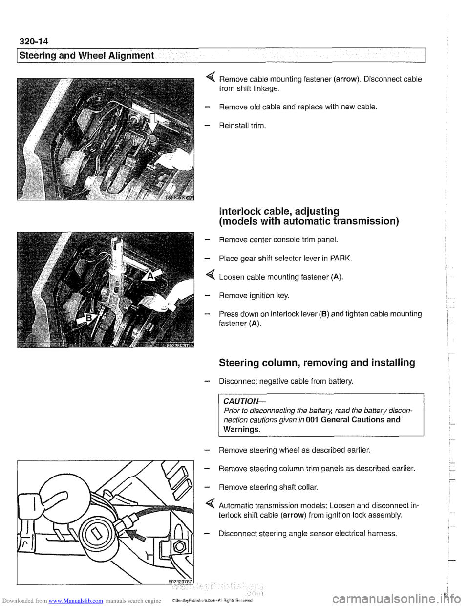
Remove cable mounting fastener (arrow). Disconnect cable
from shift
linkage.
Remove old cable and replace with new cable.
Reinstall trim.
Interlock cable, adjusting
(models with automatic transmission)
- Remove center console trim panel.
- Place gear shift selector lever in PARK.
4 Loosen cable mounting fastener (A).
- Remove ignition key.
- Press down on interlock lever (B) and tighten cable mounting
fastener (A).
Steering column, removing and installing
- Disconnect negative cable from battery.
CAUTIOI\C
Prior to disconnecting the battea read the battery discon-
nection cautions given
in 001 General Cautions and
Warninqs.
- Remove steering wheel as described earlier.
m
- Remove steering column trim panels as described earlier.
' \L/>I - Remove steerinq shaft collar
Automatic transmission models: Loosen and disconnect in-
terlock shift cable (arrow) from ignition lock assembly.
4 - Disconnect steering angle sensor electrical harness.
Page 777 of 1002
Downloaded from www.Manualslib.com manuals search engine
340-1 5
Brakes
- Remainder of installation is reverse of removal.
- Clean brake caliper mounting bolts (7 mm Allen). Replace
ones which are not in perfect condition. Do not grease.
Top up brake fluid to MAX marking.
- Before driving car, pump bralte pedal several times so that
brake pads contact brake rotors.
Check that brake fluid level is correct. Top up if necessary.
Hold ignition key for at least
30 seconds in accessory po-
sition without starting engine. This clears any fault codes in
memory and turns off brake pad warning light.
Tightening torques Brake caliper to pad carrier
(7 mm Allen)
Front caliper
30 Nm (22 It-lb)
- Rear caliper 28 Nm (21 It-lb)
Road wheel to hub
120i 10 Nm (89i7 ft-lb)
Brake rotors, removing and installing
- Raise car and remove wheels
WARNING-
Male sure that the car is firmly supported on jack stands de-
signed for the purpose. Place jack stands beneath structural
chassis points. Do not place jack stands under suspension
parts.
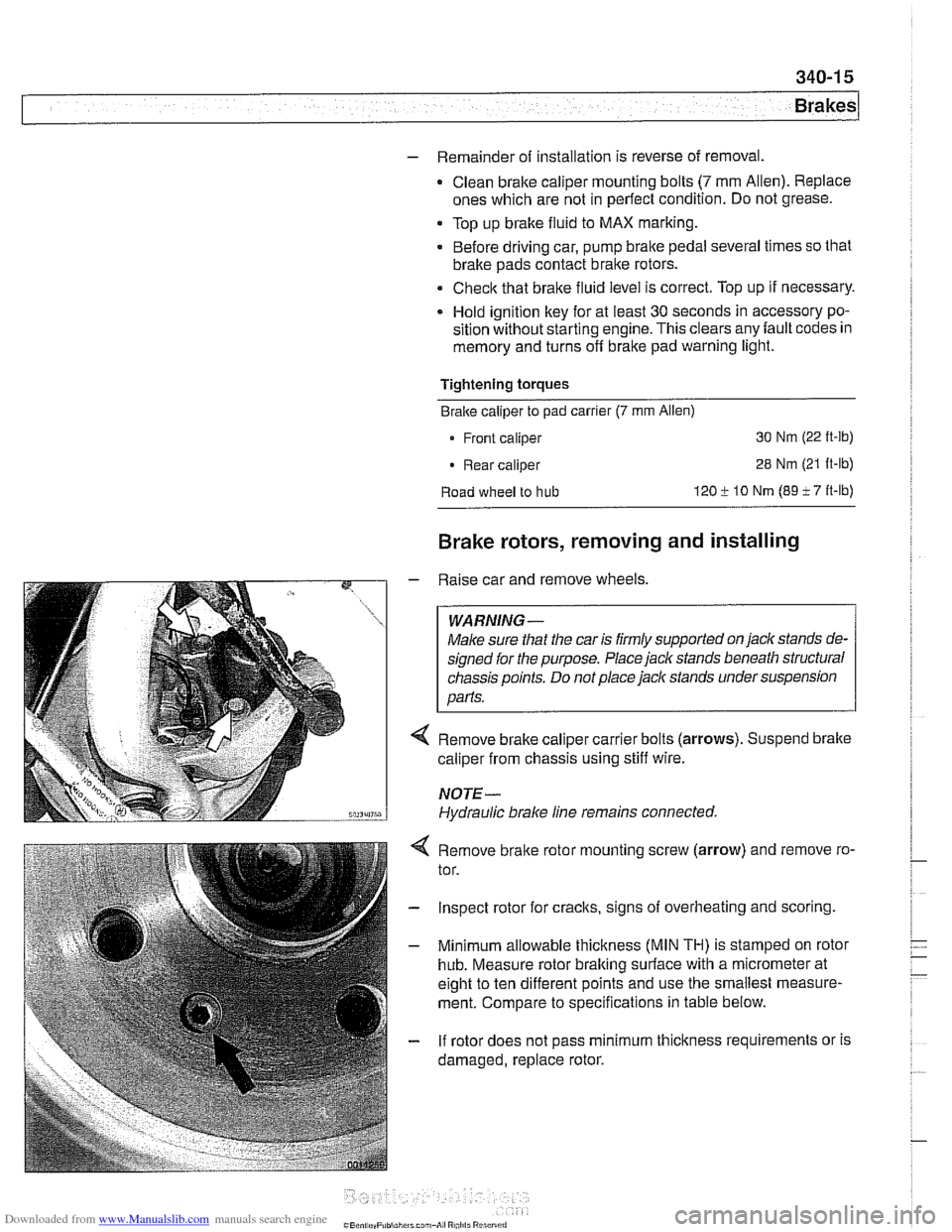
Remove brake caliper carrier bolts (arrows). Suspend brake
caliper from chassis using stiff wire.
NOTE-
Hydraulic brake line remains connected.
4 Remove bralte rotor mounting screw (arrow) and remove ro-
tor.
- Inspect rotor for cracks, signs of overheating and scoring.
- Minimum allowable thickness (MIN TH) is stamped on rotor
hub. Measure rotor braking surface with a micrometer at
eight to ten different points and use the smallest measure-
ment. Compare to specifications in table below.
- If rotor does not pass minimum thickness requirements or is
damaged, replace rotor.
Page 792 of 1002
Downloaded from www.Manualslib.com manuals search engine
1 Brakes
- Remove precharge pump mounting bracket fasteners and re-
move pump.
- Installation is reverse of removal, noting the following:
Be sure to replace rubber pump mounts if damaged
01
worn.
Bleed brakes as described earlier.
Tightening torque Brake line
to precharge pump 18 Nrn (13 ft-lb)
DSC pressure sensor (1 999 - 2002 models)
On 1999 and later DSC systems, the DSC pressure sensor is
screwed into the DSC hydraulic unit (right rear of engine com-
partment).
WARNING-
* €39 cars require special BMW service equipment to prop-
erly bleed the brakes. Removal of the
DSCpressure sensor
is not recommended unless this equipment is available. For
safety reasons, the brake system on cars with ABS must be
bled using the procedures described in this repair group.
Switch off ignition and remove
key to male sure brake
system cannot be activated.
- Disconnect electrical harness connector at switch.
- Use BMW special tool 34 5 160 to remove and install sensor.
Inspect threads and sealing surfaces for damage.
* Work quicltly to avoid excessive brake fluid leakage.
Tightening torque
Pressure sensor
to hydraulic 19 Nrn (14ft-lb)
unit
- Reconnect harness connector
- Bleed front brakes as described earlier.
- Press on brakes and check for leaks at sensor.
- Turn on ignition and firmly depress brake pedal. Check that
DSC warning light does not come on.
Page 803 of 1002
Downloaded from www.Manualslib.com manuals search engine
400-9
Body-General
Battery safety terminal
(BST)
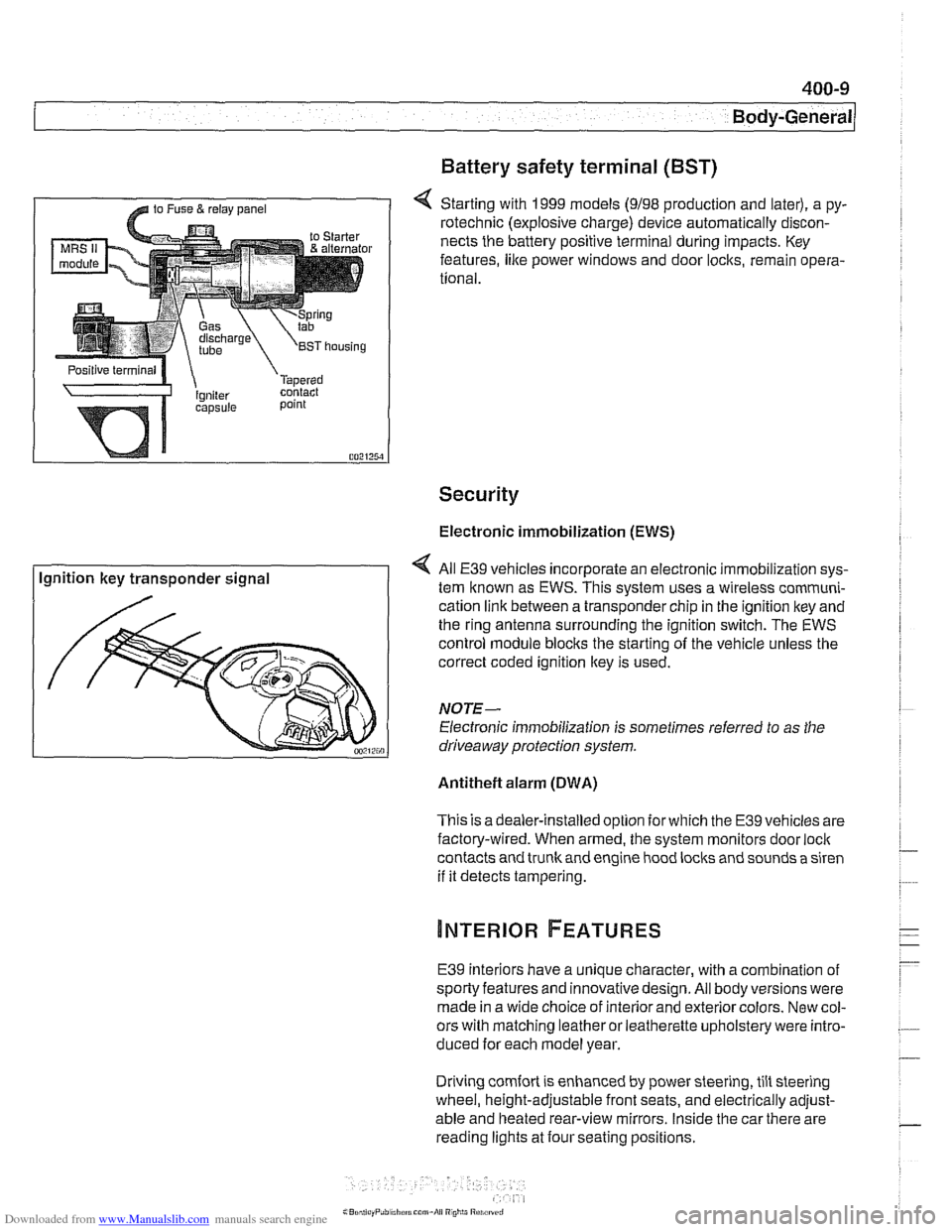
4 Starting with 1999 models (9198 production and later), a py-
rotechnic (explosive charge) device automatically discon-
nects the battery positive terminal during impacts. Key
features,
like power windows and door locks, remain opera-
tional.
Security
Electronic immobilization (EWS)
Ignition key transponder signal All
E39 vehicles incorporate an electronic immobilization sys-
tem known as EWS. This svstem uses a wireless comrnuni-
cation link between a transponder chip in the ignition key and
the ring antenna surrounding the ignition switch. The EWS
control module blocks the starting of the vehicle unless the
correct coded ignition key is used.
NOTE-
Electronic immobilization is sometimes referred to as the
driveaway protection system.
Antitheft alarm (DWA)
This is adealer-installed option for which the E39 vehicles are
factory-wired. When armed, the system monitors door
loci(
contacts and trunk and engine hood locks and sounds a siren
if it detects tampering.
E39 interiors have a unique character, with a combination
of
sporty features and innovativedesign. All body versions were
made in a wide choice of interior and exterior colors. New col-
ors with matching leather or leatherette upholstery were intro-
duced for each model year.
Driving
comfort is enhanced by power steering, tilt steering
wheel, height-adjustable front seats, and electrically adjust-
able and heated rear-view mirrors. Inside the car there are
reading lights at four seating positions.
Page 866 of 1002
Downloaded from www.Manualslib.com manuals search engine
51 2-2
I Door Windows 1
This repair group covers door glass, window regulator and
power window motor repair information.
CA U JIO&
All E39 models are equipped with side-impact airbags in the
front doors. Some models are also equipped with
airbags in
the rear doors. Be sure to read the
airbag warnings and cau-
tions in 721
Airbag System (SRS).
Electric window switch replacement is covered in 612
Switches.
The windshield, rear window, fixed rear doorglass, and cargo
compartment glass (Sport Wagon only) are bonded using
special adhesives and tools. It is recommended that bonded
glass replacement be done by an authorized
BMW service fa-
cility or an automotive glass installer.
Special tools
Some window repair operations require special tools.
Power windows
- Power window features in E39 models include:
Control of the front and rear door window motors is carried
out directly by the General Module (GM
Ill).
One-touch operation in both directions on all four windows.
Cable type window regulator used for all door windows.
. Anti-trap protection provided by pressure sensitive finger
guard.
Right front and each rear door has a single window switch
located in door handle trim.
Rear door window switches can be deactivated by press-
ing child lock-out switch in the driver's window switch block.
Convenience closinglopening of the windows from driver's
loci( cylinder or convenience opening only from remote un-
lociting feature (FZV) remote key.
Window (FZV) operation can be owner customized with
Car Memory function. See 515 Central Locking and Anti-
Theft.
After ignition is switched off, electric windows can be oper-
ated until a door is opened or until
I6 minutes has elapsed.
The GM
IiI bases window motor end position on current
draw (load). There is a maximum window motor run time of
6 seconds. The motor is then switched off even if the end
position load sensor fails.
Page 868 of 1002
Downloaded from www.Manualslib.com manuals search engine
51 2-4
I Door Windows
/ Anti-trap strip
Power window motors
The window motors are mounted on cable regulators. The
window motor control circuit consists of two wires for operat-
ing the motor in both directions.
The motors are activated by relays in the GM
Ill. The relays
provide either power or ground depending on the direction of
window travel. The GM
Ill controls the polarity based on a re-
quest to run the window from a window switch or a conve-
nience
openinglclosing signal.
Convenience openinglclosing
The GM Iii provides the convenience openlclose feature, pro-
viding control of the power windows (and sunroof) from out-
side the vehicle with the key in the driver's door lock. The FZV
(remote key) provides the same function for window opening
only.
Anti-trap protection is active during convenience closing from
the driver's door lock.
If the GM receives a request to operate convenience closing
or opening for more than
110 seconds, the function is deacti-
vated and a
fault code is stored.
Window anti-trap protection
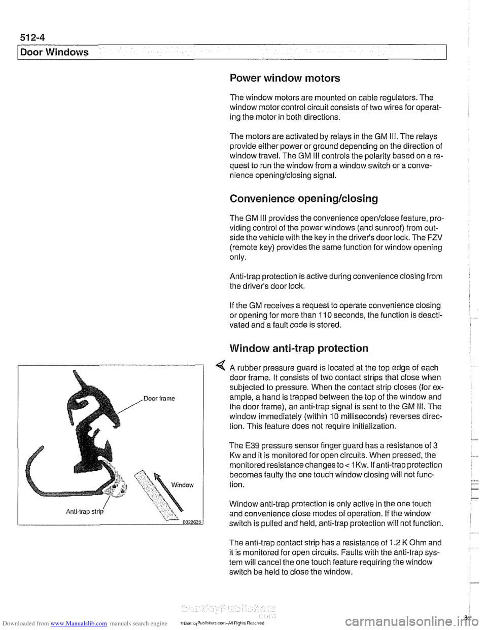
4 A rubber pressure guard is located at the top edge of each
door frame. It consists of two contact strips that close when
subjected to pressure. When the contact strip closes (for ex-
ample, a hand is trapped between the top of the window and
the door frame), an anti-trap signal is sent to the GM
Ill. The
window immediately (within
10 milliseconds) reverses direc-
tion. This feature does not require
initialization.
The E39 pressure sensor finger guard has a resistance of 3
Kw and it is monitored for open circuits. When pressed, the
monitored resistance changes to
< 1 Kw. if anti-trap protection
becomes faulty the one touch window closing will not func-
tion.
Window anti-trap protection is
only active in the one touch
and convenience close modes of operation. If the window
switch is pulled and held, anti-trap protection will not function.
The anti-trap contact strip has a resistance of
1.2 K Ohm and
it is monitored for open circuits. Faults with the anti-trap sys-
tem will cancel the one touch feature requiring the window
switch be held to close the window.
Page 870 of 1002
Downloaded from www.Manualslib.com manuals search engine
Door Windows
Window anti-trap strip, testing
- To test function of anti-trap strip on any window:
With key
ON and window down, pull up window switch to
second detent, thus activating one-touch close operation.
Insert wooden block or other soft object between glass
and upper door frame.
Window should contact block, then immediately reverse
direction and lower by approximately
25 mm (1 in).
NOTE-
Anti-trap strip is integrated into the molding strip of the door
window frame.
Front window anti-trap strip, removing
- Remove front door panel and vapor barrier as described in
411 Doors.
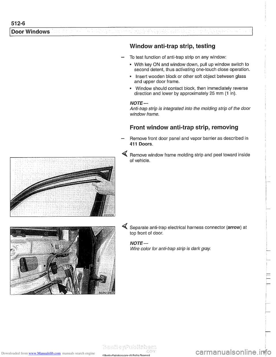
< Remove window frame mold~ng strlp and peel toward inside
7 of vehrcle.
Separate anti-trap electrical harness connector
top front of door.
NOTE-
Wire color for anti-trap strip is dark gray.
(arrow) at
Page 895 of 1002
Downloaded from www.Manualslib.com manuals search engine
51 5 Central Locking and Anti-Theft
........................... General .51 5.2
Central Locking ................... .51 5.2
General Module
..................... .51 5.2
Central locking inputs and outputs
....... .51 5.3
Doorlocks
........................... 515-5
Trunklock
........................... 515-7
Remote entry (FZV)
.................. .51 5.7
Remote entry (FZV) inputs and outputs ... .51 5.8
Car Memory I Key Memory ............ .51 5.12
Trunk lid soft close (SCA)
............. .51 5.13
SCA subsystem
.................... .51 5.14
........ Tailgate and rear window locks
.51 5.14
Sport Wagon tailgate and rear
window
lock schematic ............... .51 5.15
Door Handles and Locks .......... .51 5.16
Door handle (outer), removing
and installing
....................... .51 5.16
Door latch, removing and installing
..... .51 5.17
Outer door lock cylinder, removing
and installing
....................... .51 5.18
Trunk Lock Assembly ............. 515-1 9
Trunk lock. removing and installing
...... 515-19
Trunk lock striker plate. removing
and installing
....................... 515-20
Tailgate lock. emergency release
....... 515-21
... Electronic Immobilization (EWS) 515-21
EWS variations
..................... 515-22
......... EWS control module. replacing 515-23
Transmitter
1 receiver module .......... 515-23
....................... Ring antenna 515-23
Anti-theft System (DWA) ........... 51 5-24
DWA LED Status
.................... 51 5-24
Tilt sensor
......................... 515-24
Interior protection .................... 51 5-25
Glass breakage sensors
.............. 515-26
Emergency disarming
................ 51 5-26
Page 896 of 1002
Downloaded from www.Manualslib.com manuals search engine
51 5-2
/Central Locking and Anti-Theft
This section covers repair information for door, trunk and car-
go compartment locks, central locking, electronic
immob~liza-
tion (EWS) and anti-theft alarm (DWA).
€39 cars are equipped with sophisticated self-diagnostic elec-
trical systems. When experiencing malfunctions relating to
central locking. EWS or anti-theft systems, start the diagnosis
process using the
BMW service tester DIS, GT 1, MoDiC or
equivalent scan tool. An advanced diagnostic scan tool can
usually pinpoint electrical faults quickly and safely.
Additional electrical information can be found in:
610 Electrical Component Locations
ELE Electrical Wiring Diagrams
Central locking in E39 vehicles controls the door
locks, trunk
or tailgate lock and fuel filler flap lock. The control module for
the Central Body Electronics system (ZKE
Ill), lknown as the
General Module (GM
Ill), controls central locking.
ZKE
Ill manages the following central locking related func-
tions:
Central locking
* Keyless entry
Key memory
Power trunk release
Electric opening of tailgate
DWA alarm system
Diagnosis
General Module
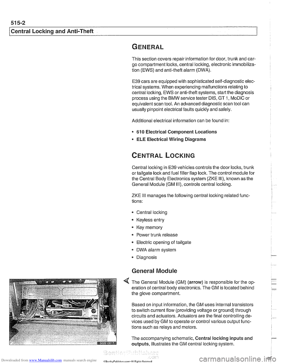
4 The General Module (GM) (arrow) is responsible for the op-
eration of central body electronics. The GM is located behind
the glove compartment.
Based on input information, the GM uses internal transistors
to switch current flow (providing voltage or ground) through
circuits and actuators. Actuators are the final controlling de-
vices used by GM to operate or control various output func-
tions such as relays and motors.
The accompanying schematic, Central locking inputs and
outputs, illustrates the GM central locking system.
Page 898 of 1002
Downloaded from www.Manualslib.com manuals search engine
51 5-4
I Central Locking and Anti-Theft
Driver's door lock
The
lock/unlock signals are sent as input to the door module
from two microswitches on the lockcylinder. The driver's door
module carries out the locking
/ unlocking functions of the
driver's door through its final stage control.
The signal to lock the remaining doors, trunk or tailgate and
fuel flap is sent over the P-Bus to the GM and the passenger
door module. Activation of the passengers door
loclt is carried
out by the passenger door module. The rear doors, trunlt or
tailgate and fuel flap are
locked by the f~nal stage in the GM.
When
locked from the outside, all doors are set to the double
lock position and the GM will not carry out any unlock com-
mands from the central
loclc button or remote trunk release
button.
Selective unlocking
When unlocking with the key or the remote transmitter, the
first unloclcrequestwill only unlock the driver'sdoor. A second
unlock request will unlock the remaining doors, trunk or tail-
gate and fuel flap.
Trunk locking
I
The vehicle can be locked/unlocked from the trunlc loclc cylin-
der. The GM locks the trunk or tailgate, rear doors and fuel fill-
er. The locking command is passed over the P-Bus to the
respective door modules to lock the driver's and passengers
doors.
Locking the trunk and removing the key in the
hor~zontal posi-
tion will set the valet lock and prevent opening of the trunlt
with the central locking system.
Central locking switch
-
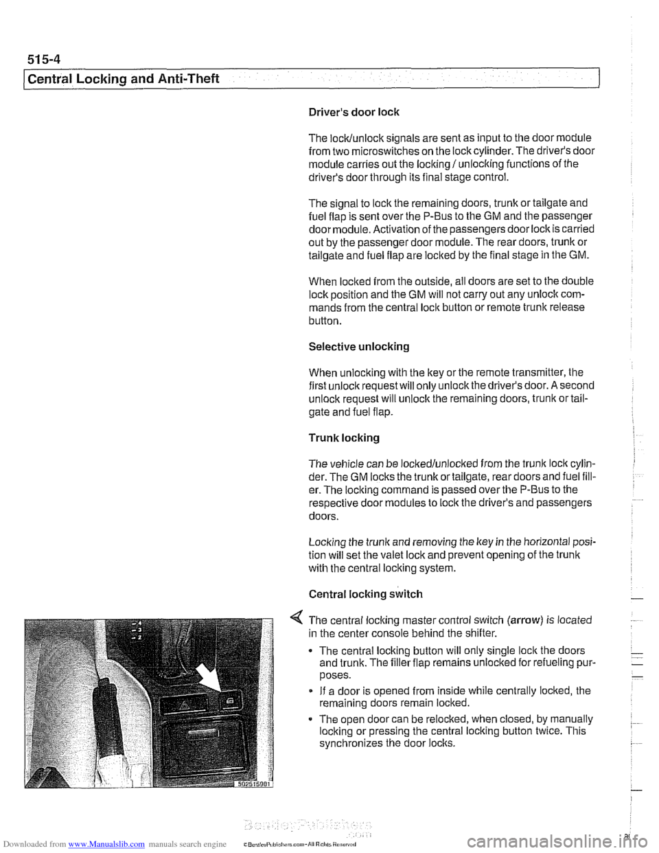
< The central locking master control switch (arrow) is located
in the center console behind the shifter.
The central locking button will only single
loclt the doors
and trunk. The filler flap remains unloclted for refueling pur-
poses.
If a door is opened from inside while centrally locked, the
remaining doors remain locked.
The open door can be relocked, when closed, by manually
locking or pressing the central locking button twice. This
synchronizes the door
locks.