locking BMW 540i 1998 E39 Owner's Guide
[x] Cancel search | Manufacturer: BMW, Model Year: 1998, Model line: 540i, Model: BMW 540i 1998 E39Pages: 1002
Page 199 of 1002
Downloaded from www.Manualslib.com manuals search engine
11 6-23
Cylinder Head and Valvetrain
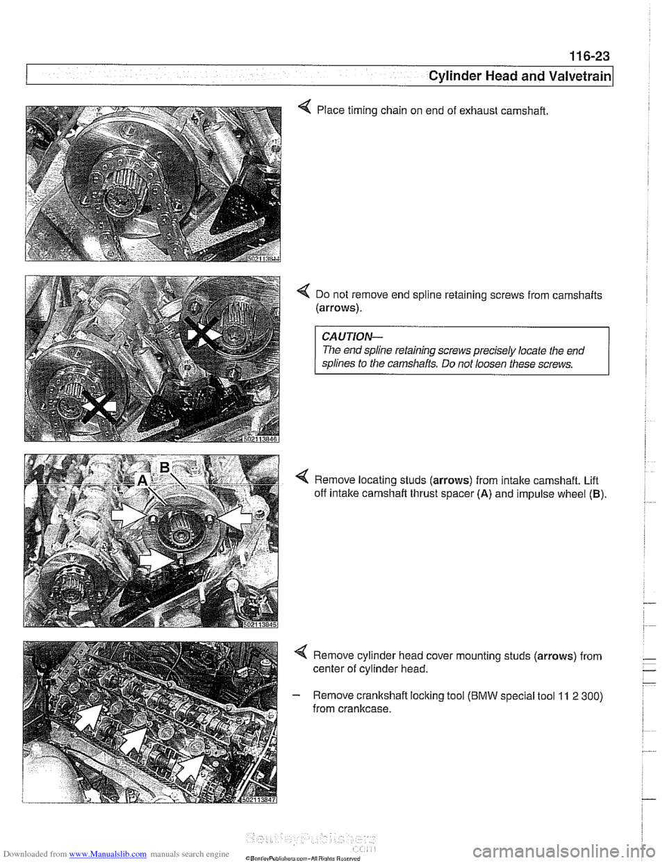
Place timing
chain on end of exhaust camshaft
4 Do not remove end spline retaining screws from camshafts
(arrows).
CAUTION-
The end spline retaining screws precisely locate the end
splines to the camshafts. Do not loosen these screws.
Remove locating studs (arrows) from
intake camshaft. Lift
off intake
camshaft thrust spacer (A) and impulse wheel (B)
4 Remove cylinder head cover mounting studs (arrows) from
center of cylinder head.
- Remove crankshaft locking tool (BMW special tool 11 2 300)
from cranltcase.
Page 212 of 1002
Downloaded from www.Manualslib.com manuals search engine
1 16-36
I Cylinder Head and Valvetrain
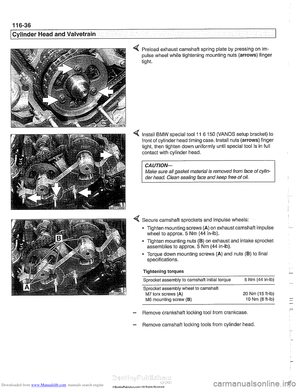
4 Preload exhaust camshaft spring plate by pressing on im-
pulse wheel while tightening mounting nuts (arrows)
fingel
tight.
4 Install BMW special tool 11 6 150 (VANOS setup bracket) to
front of cylinder head timing case. Install nuts (arrows) finger
tight, then tighten down uniformly until special tool is in full
contact with cylinder head.
CAUTION--
Male sure aNgas1ef material Is removed from face of cyiin-
der head. Clean sealing face and keep free of oil.
4 Secure camshaft sprockets and impulse wheels:
Tighten mounting screws (A) on exhaust camshaft impulse
wheel to approx.
5 Nm (44 in-lb).
Tighten mounting nuts (B) on exhaust and intake sprocket
assemblies to approx.
5 Nm (44 in-lb).
Torque down mounting screws (A) and nuts (B) to final
specifications.
Tightening torques Sprocket assembly to camshaft initial torque
5 Nm (44 in-lb)
Sprocket assembly wheel to carnshaft
M7 tom screws (A) 20 Nm (15 ft-lb)
M6 mounting sciew (6) I0 Nm (8 ft-lb) - - -
- - Remove crankshaft locking tool from crankcase.
- Remove camshaft locking tools from cylinder head.
Page 214 of 1002
Downloaded from www.Manualslib.com manuals search engine
I Cylinder Head and Valvetrain
- Remove adjustable primary timing chain tensioner tool and
reinstall primary chain tensioner cylinder to cylinder head.
Tightening torque
Primary chain tensioner cylinder
to 70 Nm (52 ft-lb)
cylinder head
- Remove flywheel locking tool from crankcase. Replace spe-
cial tool bore sealing plug.
- Remove camshaft locking tools from cylinder head
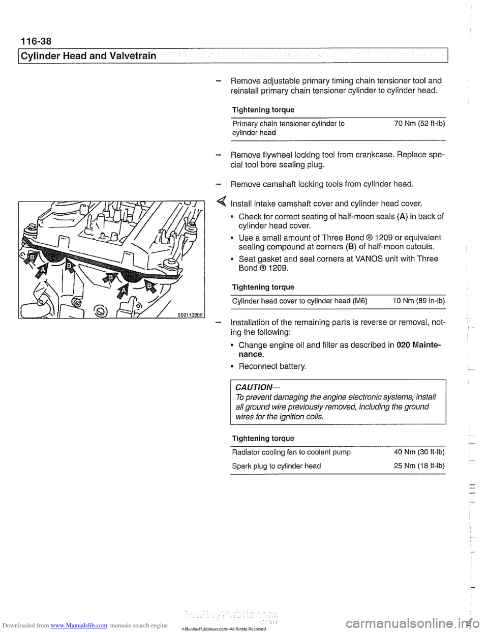
Install intake camshaft cover and cylinder head cover.
Check for correct seating of half-moon seals (A) in back of
cylinder head cover.
Use a small amount of Three Bond
8 1209 or equivalent
sealing compound at corners
(B) of half-moon cutouts.
Seat gasket and seal corners at VANOS unit with Three
Bond
@ 1209.
Tightening torque Cylinder head cover to cylinder head
(M6) 10 Nm (89 in-lb)
- Installation of the remaininq parts is reverse or removal, not- -
ing the following:
Change engine
011 and f~lter as descr~bed in 020 Mainte-
nance.
Reconnect battery.
To prevent damaging the engine electronic systems, install
all ground wire previously removed, including the ground
wires for the ignition coils.
Tightening torque
-
Radiator cooling fan to coolant pump 40 Nm
(30 ft-ib)
Spark plug to cylinder head
25 Nm (18 ft-ib)
Page 215 of 1002
Downloaded from www.Manualslib.com manuals search engine
Cylinder Head and valvetrain1
Camshaft removal and installation
(M62 engine)
Camshafts, removing (M62 engine)
Special
BMW service tools should always be used to remove
and install the camshafts. Removal of the camshafts without
the special tools can result in personal injury and lor cylinder
head damage.
NOTE-
Cylinder bank 1-4 is referred to as the right cylinder bank
and is located on the passenger side. Cylinder bank 5-8 is
referred to as the left cylinder bank and is located on the driv-
er's side.
WARNING-
Allow enqine to cool before beqinninq this procedure. 1
- Disconnect negative (-) cable from battery.
CAUTION-
Prior to disconnecting the battery, read the battery discon-
nection cautions
in 001 General Cautions and Warnings.
- Dra~n coolant. See 170 Radiator and Cooling System.
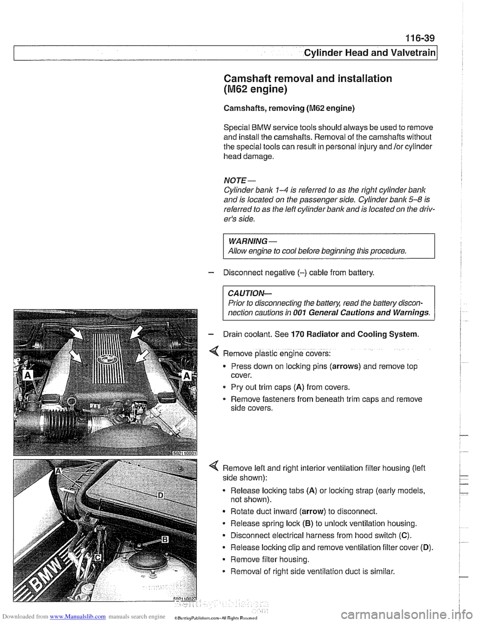
Remove plastic engine covers:
Press down on locking pins (arrows) and remove top
cover.
Pry out
trlm caps (A) from covers.
Remove fasteners from beneath
trlm caps and remove
side covers.
4 Remove left and right interior ventilation filter housing (lefl
side shown):
Release locking tabs
(A) or locking strap (early models,
not shown).
Rotate duct inward (arrow) to disconnect.
- Release spring lock (6) to unloclc ventilation housing.
Disconnect electrical harness from hood switch
(C).
Release locking clip and remove ventilation filter cover (0).
Remove filter housing.
Removal of right side ventilation duct is similar.
Page 227 of 1002
Downloaded from www.Manualslib.com manuals search engine
- -.
Cylinder Head and valvetrain1
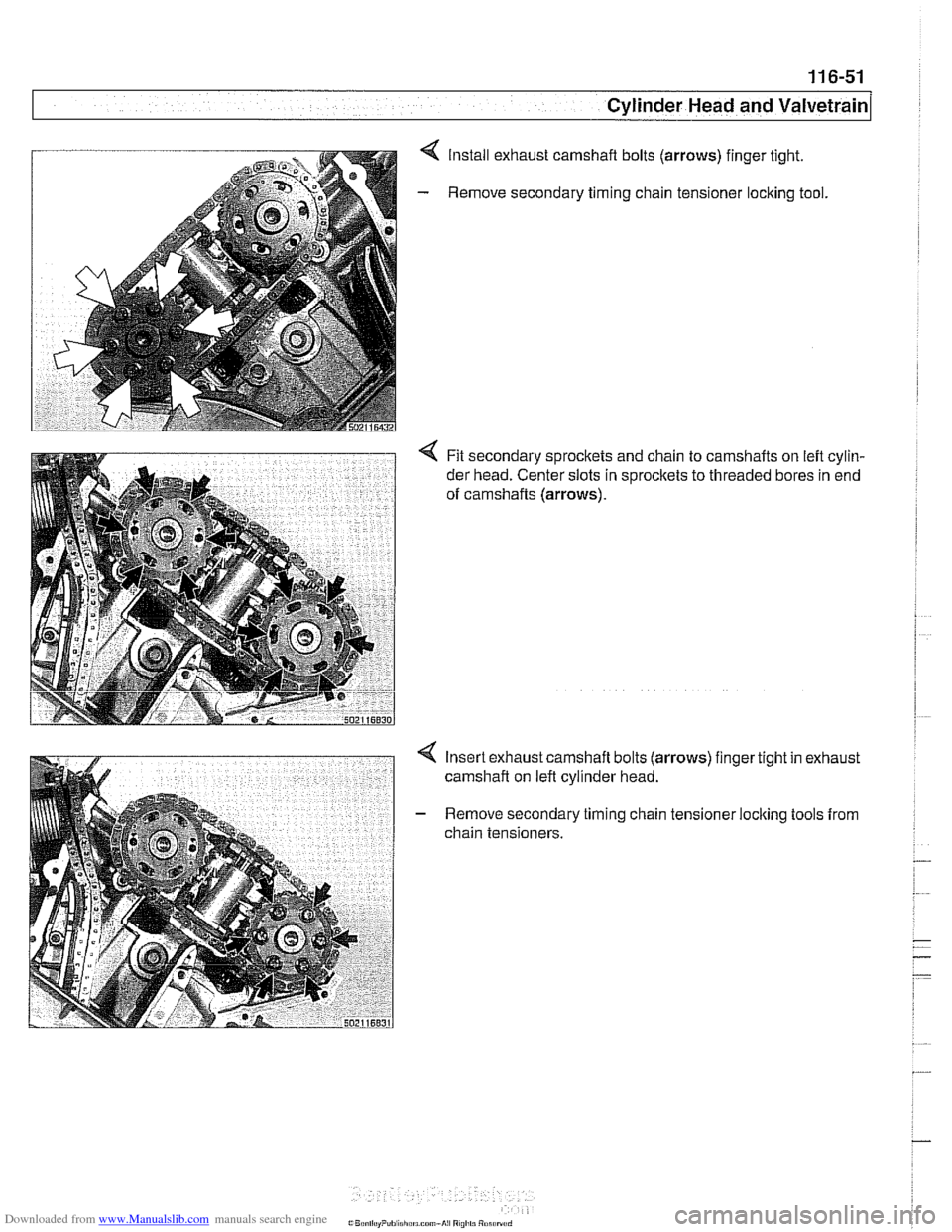
Install exhaust camshaft bolts (arrows) finger tight.
Remove secondary timing chain tensioner
loclting tool.
< Fit secondary sprockets and chain to camshafts on left cylin-
der head. Center slots in sprocltets to threaded bores in end
of camshafts
(arrows).
Insert exhaust camshaft bolts (arrows) finger tight in exhaust
camshaft on left cylinder head.
Remove secondary timing chain tensioner locking tools from
chain tensioners.
Page 229 of 1002
Downloaded from www.Manualslib.com manuals search engine
Cylinder Head and valvetrain'
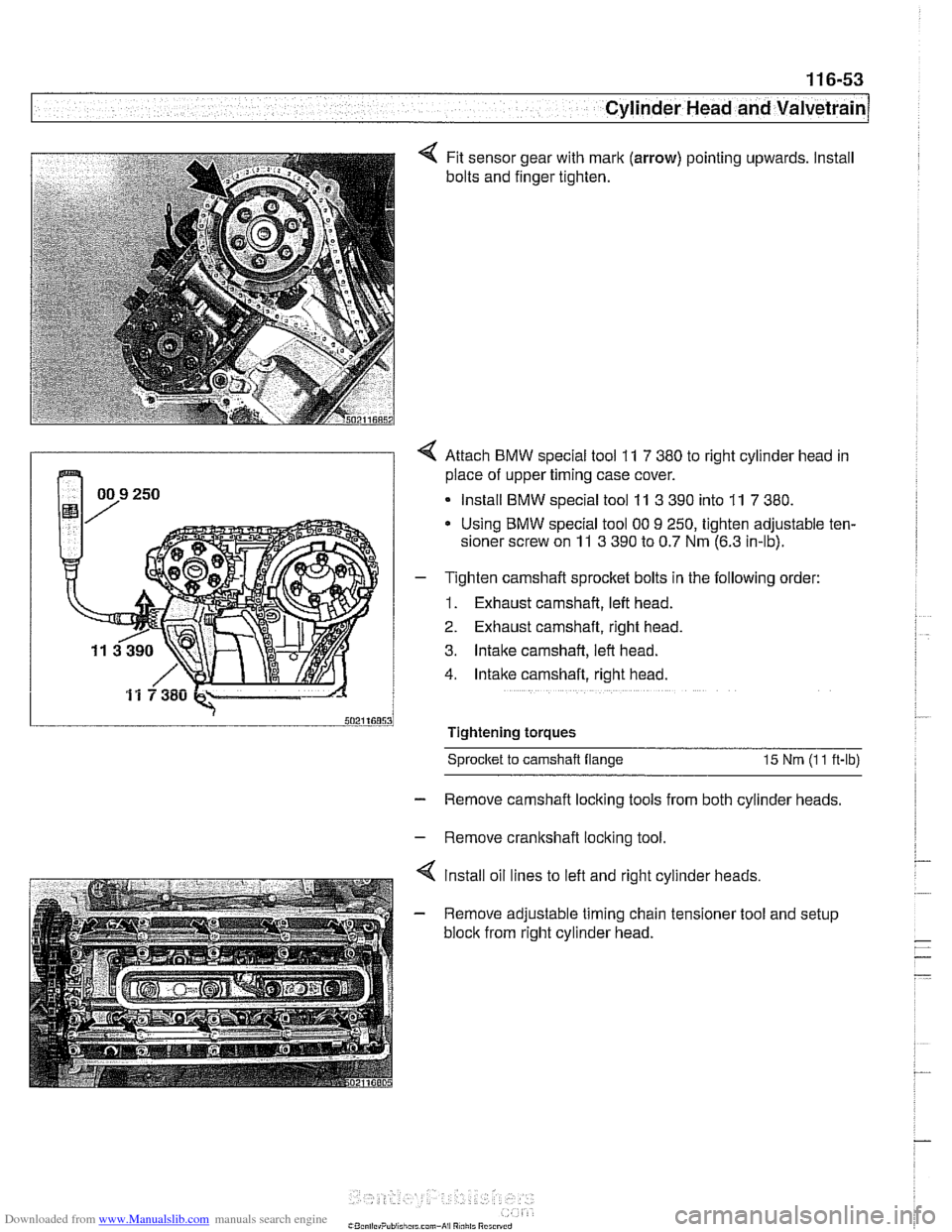
Fit sensor gear with mark (arrow) pointing upwards. Install
bolts and finger tighten.
4 Attach BMW special tool 11 7 380 to right cylinder head in
place of upper timing case cover.
Install BMW special tool
11 3 390 into 11 7 380.
Using BMW special tool 00 9 250, tighten adjustable ten-
sioner screw on
11 3 390 to 0.7 Nm (6.3 in-lb).
- T~ghten camshaft sprocket bolts in the following order:
1. Exhaust camshaft, left head.
2. Exhaust camshaft, right head.
3. Intake camshaft, left head.
4. Intake camshaft, right head.
Tightening torques Sprocket
to camshaft flange 15 Nm (I 1 ft-lb)
- Remove camshaft locking tools from both cylinder heads.
- Remove crankshaft locking tool.
4 lnstall oil lines to left and right cylinder heads.
- Remove adjustable timing chain tensioner tool and setup
block from right cylinder head.
Page 239 of 1002
Downloaded from www.Manualslib.com manuals search engine
1 17-3
Camshaft Timing Chain
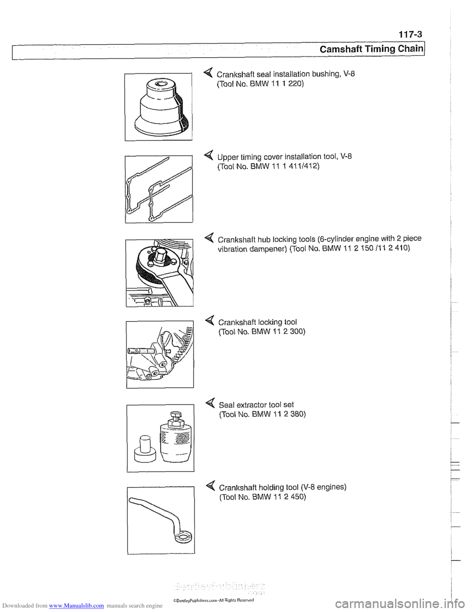
4 Crankshaft seal installation bushing, V-8
(Tool No. BMW 11 1 220)
4 Upper timing cover Installation tool, V-8
(Tool No. BMW 11
1 41 11412)
4 Crankshaft hub locking tools (6-cylinder engine with 2 piece
vibration dampener) (Tool No. BMW
11 2 150 11 1 2 410)
4 Cranltshaft loclting tool
(Tool No. BMW
11 2 300)
I I 4 Seal extractor tool set
(Tool No. BMW 11 2 380)
Page 240 of 1002
Downloaded from www.Manualslib.com manuals search engine
[Camshaft Timing Chain
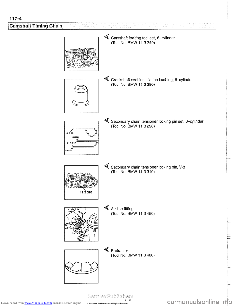
4 Camshaft locking tool set, 6-cylinder
(Tool No. BMW
11 3 240)
- 4 Crankshaft seal installation bushing. 6-cylinde~
4 Secondary chain tensioner locking pin set. 6-cylinder
(Tool No.
BMW 11 3 290)
11 3292
4 Secondary chain tensioner loclting pin, V-8
(Tool No. BMW 11 3 310)
4 Air line fitting
(Tool No. BMW
11 3 450)
4 Protractor
(Tool No. BMW
11 3 460)
Page 243 of 1002
Downloaded from www.Manualslib.com manuals search engine
Camshaff Timing Chain
NOTE-
Mark direction of belt rotation if reusing belt.
- Remove vibration damper mounting bolts and remove vibra-
tion damper and pulley from hub.
NOTE- The M52
6-cylinder engine uses a 2-piece vibration damper
and hub assembly.
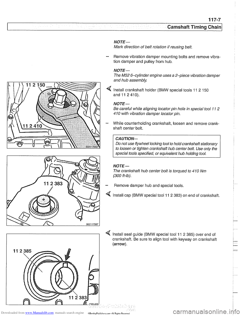
4 Install crankshaft holder (BMW special tools 11 2 150
and11 2410).
NOTE
-
Be careful while aligning locator pin hole in special tool 11 2
410 with vibration damper locatorpin.
- While counterholding crankshaft, loosen and remove crank-
shaft center bolt.
CAUTION-
Do not use flywheel locking tool to hold crankshaft stationary
to loosen or tighten crankshaft hub center bolt Use only the
special tools specified, or equivalent hub holding tool.
NOTE- The cranlshaft hub center bolt is torqued to 4
10 Nm
(300
ft-16).
- Remove damper hub and special tools.
4 Install cap (BMW special tool 11 2 383) on end of cranltshaft.
4 Install seal guide (BMW special tool 11 2 385) over end of
crankshaft. Be sure to align tool with keyway on crankshaft
(arrow).
Page 257 of 1002
Downloaded from www.Manualslib.com manuals search engine
Camshaft Timing Chain/ - - - - - - . - - . - .
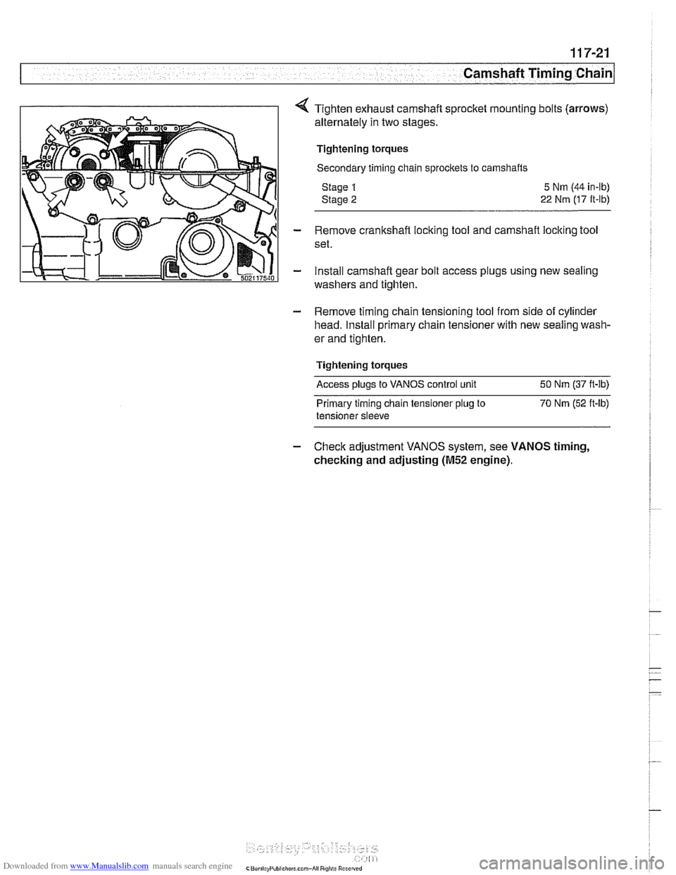
Tighten exhaust camshaft sprocket mounting bolts (arrows)
alternately in two stages.
Tightening torques
Secondary timing chain sprocltets to camshafts
Stage
1
Stage 2
5 Nm (44 in-lb)
22 Nm (17 ft-lb)
- Remove crankshaft locking tool and camshaft locking tool
set.
- install camshaft gear bolt access plugs using new sealing
washers and tighten.
- Remove timing chain tensioning tool from side of cylinder
head. Install primary chain tensioner with new sealing wash-
er and tighten.
Tightening torques
Access plugs to VANOS control unit 50 Nm (37 ft-lb)
Primary timing chain tensioner
plug to 70 Nm (52 ft-lb)
tensioner sleeve
- Check adjustment VANOS system, see VANOS timing,
checking and adjusting
(M52 engine).