wheel BMW 540i 1998 E39 Repair Manual
[x] Cancel search | Manufacturer: BMW, Model Year: 1998, Model line: 540i, Model: BMW 540i 1998 E39Pages: 1002
Page 451 of 1002
Downloaded from www.Manualslib.com manuals search engine
-. -
Fuel Injection
I 68 1 / Not used
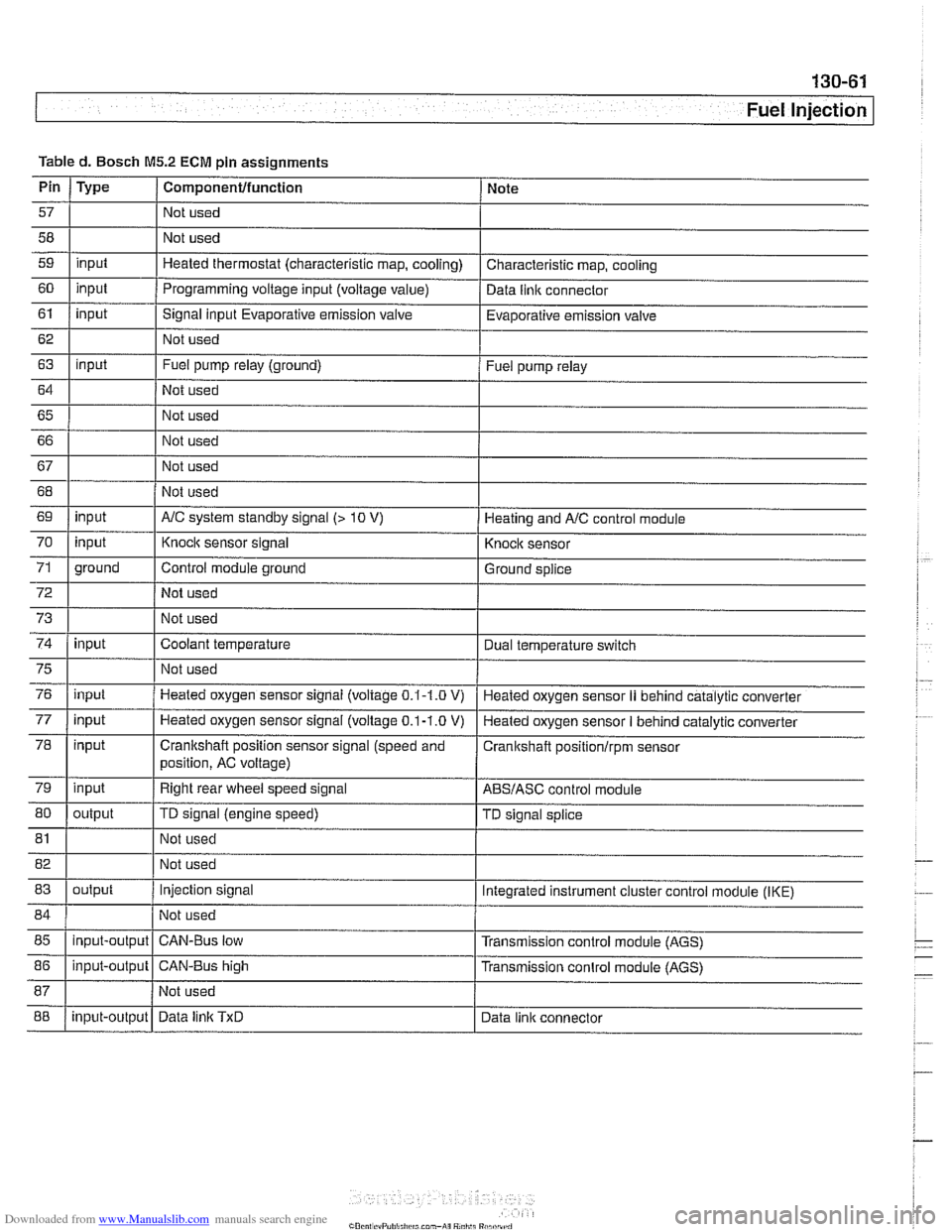
Table
d. Bosch
M5.2 ECM pin assignments
I I I
69 1 input I AIC system standby signal (> 10 V) 1 Heating and AIC control module
Pin
57
58
59
60
61
62
63
64
65 66
67
Type
input
input
input
input
I 70
72
73
74
Componentlfunction
Not used
Not used
Heated thermostat (characteristic map, cooling)
Programming voltage input (voltage
value)
Signal input Evaporative emission valve
Not used
Fuel pump relay (ground)
Not used
Not used
Not used
Not used
75
76
77
78
79
80
Note
Characteristic map, cooling
Data
llnlc connector
Evaporative emission valve
Fuel pump relay
71 1 ground I Control module ground I Ground splice
input
input
81
input input
input
input
output Not used
I
Knock sensor signal
Not used
Not used
Coolant temperature
82 1 I Not used
83
I I
Knock sensor
Dual temperature
swltch
Not used
Heated oxygen sensor signal (voltage
0.1-1.0 V)
Heated oxygen sensor
signal (voltage 0.1-1.0 V)
Crankshaft position sensor signal (speed and
position, AC voltage)
Right rear wheel speed signal
TD signal (engine speed)
85
I I I
Heated oxygen sensor II behind catalytic converter
Heated oxygen sensor
I behind catalytic converter
Cranitshaft positionlrpm sensor
ABSIASC control module
TD signal splice
84 1 / Not used 1
output
88
86
1 input-output 1 CAN-Bus high I Transmission conlrol module (AGS)
input-output
Injection signal
input-output Integrated instrument cluster control
module (IKE)
CAN-Bus low Transmission control module (AGS)
Data
linlc TxD Data link connector
Page 454 of 1002
Downloaded from www.Manualslib.com manuals search engine
-
Fuel Injection
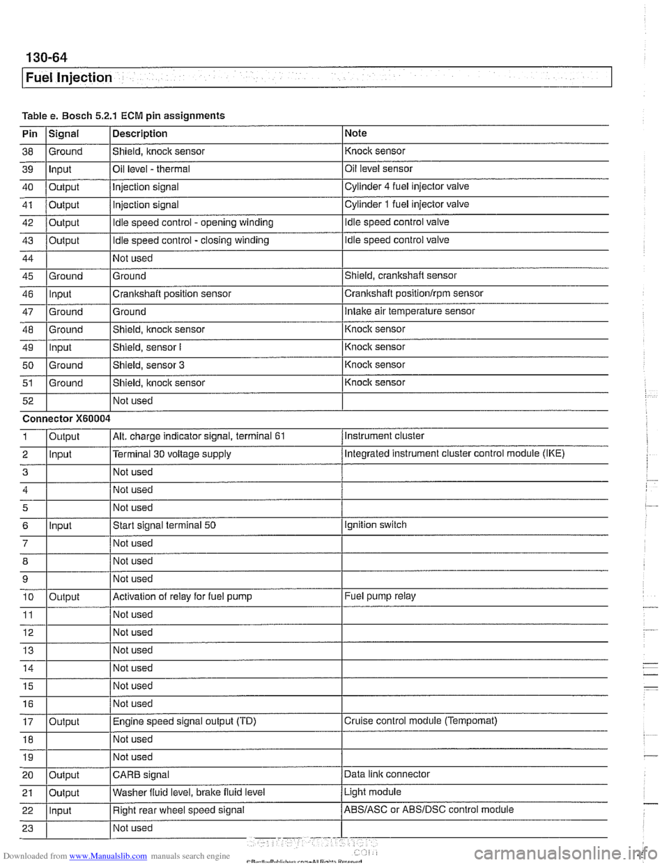
Table e. Bosch 5.2.1 ECM pin assignments
Pin
I~iqnal 1 Description 1 Note
I I I
46 llnput ICrankshaft position sensor Icrankshaft positionlrpm sensor
38
39
40
41
42
43
44
45 Ground Input
Output
Output
Output
Output
Ground
47
48
49
50
51
Not used
I Not used
52
Shield, knock sensor
Oil level
- thermal
Injection signal
injection signal
Idle speed control - opening winding
Idle speed control - closing winding
Not used
Ground
Ground
-- Ground Input
Ground
Ground Not used Knock sensor
Oil level sensor
Cylinder
4 fuel injector
valve
Cylinder
1 fuel injector valve
Idle speed control valve
Idle speed control valve
Shield, crankshaft sensor
5
6
7
12 Not used
Ground
Intake air temperature sensor
Connector
X60004
8
9 10
11
14 1 1 Not used I
Shield, knock sensor
Shield, sensor
I
Shield, sensor 3
Shield, itnock sensor
Input
- Knoclc sensor
Knock sensor
Knock sensor
Knock sensor
Instrument cluster
Output
2 llnput l~erminal 30 voltage supply /Megrated instrument cluster control module (IKE)
Alt. charge indicator signal, terminal 61 1
Not used
Start signal terminal
50
Not used
15
16
17
18
Output
Ignition switch
Not used
Not used
Activation of relay for fuel pump
Not used
19
Fuel pump relay
Output Not used
I I I 20 loutput ICARB signal /Data link connector
Not
used
Not used
Engine speed signal output (TD)
Not used
Light module
21
Cruise control module (Tempomat)
22 llnput I Right rear wheel speed signal /ABS/ASC or ABSIDSC control module
Oulput
Washer
fluid level,
brake fluid level
Page 464 of 1002
Downloaded from www.Manualslib.com manuals search engine
130-74
I Fuel Injection
Evaporative system pressure leak
diagnosis, overview
The M62 TU engine is equipped wlth an evaporative fuel sys-
tem pressure leak diagnosis system. The main component of
this system is the leakdiagnosis pump (LDP). The function of
the LDP is to pressurize the fuel tank and the evaporative
emission system for the purpose of detecting leaks.
This system iscapable of detecting a
lealcas small as0.5 mm.
The LDP, located in the left rear wheel housing, contains the
following:
Vacuum chamber. Pneumatic pump chamber
DME activated vacuum solenoid
Reed switch (provides switched voltage
feedback signal to
DME).
The vacuum supply line is in the wiring harness from the en-
gine compartment and runs down the driver's side of the vehi-
cle.
The canister vent valve is
~ntegrated into the LDP, which IS
electrically controlled by the ECM. The canister vent valve is
opened to provide fresh air entry into the fuel system only dur-
ing purge operation.
- Purge operation characteristics:
Off idle through full throttle: purge valve opened by pulse
width modulated (PWM) control of the ECM. PWM duty cy-
cle varies by engine operating conditions
(e.g. warm idle,
purge valve opened slightly; cold
idleldecel with engine
temp
< 67" C. purge valve always closed).
Page 469 of 1002
Downloaded from www.Manualslib.com manuals search engine
Fuel Injection I
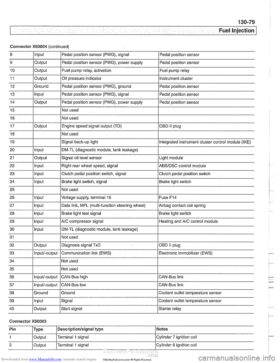
Connector X60004 (continued)
8 10
11
12
13
14
15
16
9
Output 0
Input
17
18
19
20
21
22
23
24
25
26
27
28
29
30
31
32
33
34
35
36
39
llnput lsignal l~oolant outlet temperature sensor
Output
Output
Ground
Input
Output
I I - I
40 /output Istart signal Istarter relay
Pedal position sensor (PWG), signal
Output Input
Output
input
Input
Input
Input
Input
Input
input
Input
Output
Input/-output
Input/-output
37
Connector X60003
Pedal position sensor
Fuel pump relay, activation
Oil pressure indicator Pedal position sensor (PWG), ground
Pedal position sensor (PWG), signal
Pedal position sensor (PWG), power supply
Not used
Not used Fuel
pump relay
Instrument cluster
Pedal position sensor
Pedal position sensor
Pedal position sensor
Engine speed signal output (TD)
Not used
Signal
back-up light
DM-TL (diagnostic module,
tank leakage)
Signal oil level sensor
Right rear wheel speed, signal
Clutch pedal position switch, signal
Brake light switch, signal
Not used
Voltage supply, terminal
15
Data link, MFL (multi-function steering wheel)
Brake light test signal
AJC compressor signal
DM-TL (diagnostic module, tank
leakage)
Not used
Diagnosis signal
TxD
Communication link (EWS)
Not used
Not used
CAN-BUS hiqh
38 1 Ground l~round I Coolant outlet temperature sensor
OED II plug
Integrated instrument cluster control module (IKE)
Light module
ABSIDSC control module
Clutch pedal position switch
Brake light switch
Fuse
F14
Airbag contact coil spring
Brake light switch
Heating and
A/C control module
OBD
II plug
Electronic immobilizer (EWS)
CAN-Bus link
CAN-Bus link
Input/-output CAN-Bus low
Page 492 of 1002
Downloaded from www.Manualslib.com manuals search engine
160-22
Fuel Tank and Fuel Pump
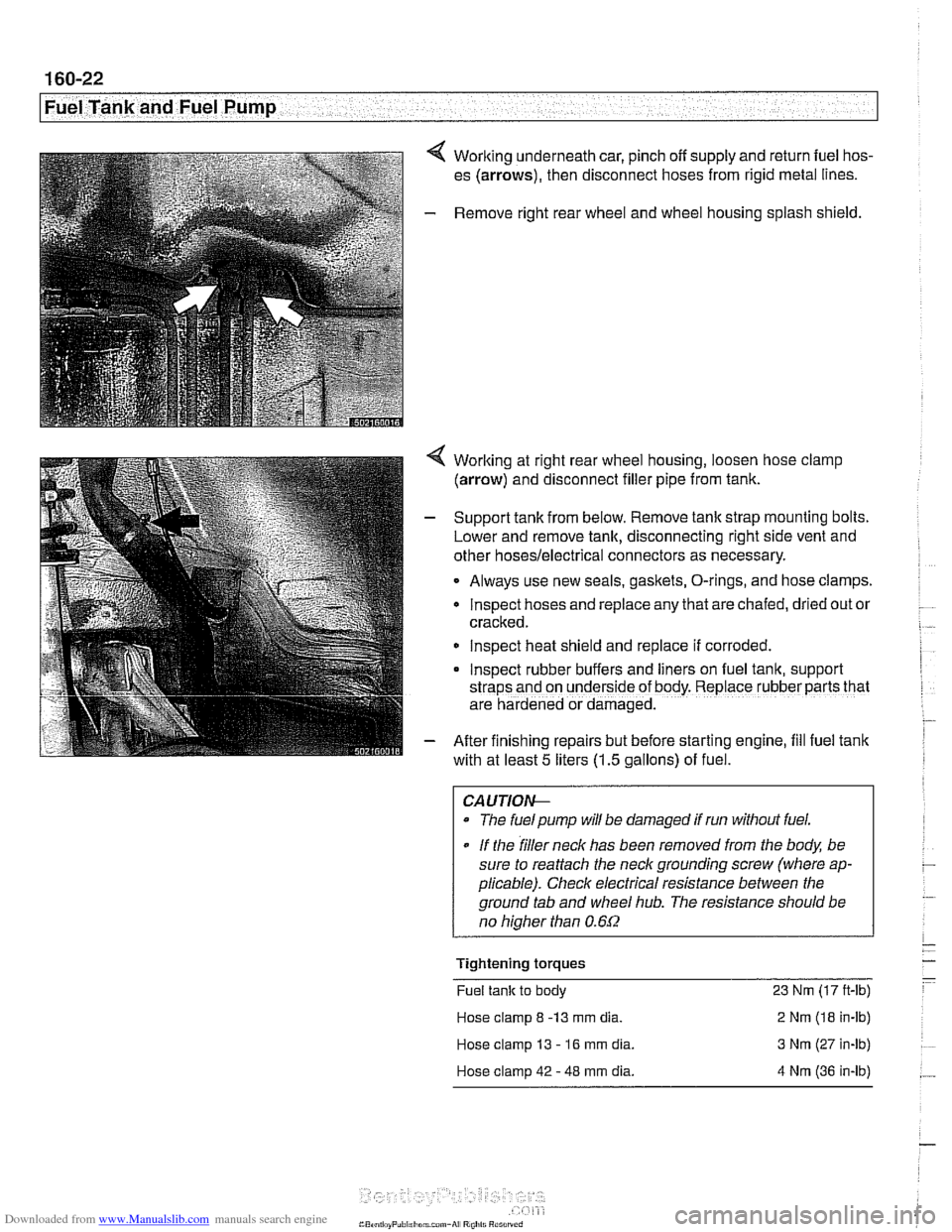
4 Working underneath car, pinch off supply and return fuel hos-
es (arrows), then disconnect hoses from rigid metal lines.
- Remove right rear wheel and wheel housing splash shield.
4 Worlting at right rear wheel housing, loosen hose clamp
(arrow) and disconnect filler pipe from tank.
- Support tank from below. Remove tank strap mounting bolts.
Lower and remove tank, disconnecting right side vent and
other
hoses/electrical connectors as necessary.
Always use new seals, gaskets, O-rings, and hose clamps.
lnspect hoses and replace any that are chafed,
dr~ed out or
cracked.
lnspect heat shield and replace if corroded.
Inspect rubber buffers and
hers on fuel tank, support
straps and on underside of body. Replace rubber parts that
are hardened or damaged.
- After finishing repairs but before starting engine, fill fuel tank
with at least
5 liters (1.5 gallons) of fuel.
CAUTlOI+
The fuelpump will be damaged if run without fuel.
* If the filler neck has been removed from the body, be
sure to reattach the
neck grounding screw (where ap-
plicable). Check electrical resistance between the
ground tab and wheel
hub. The resistance should be
no
hiaher than 0.6f2
Tightening torques
Fuel tank to body 23 Nm (17 ft-lb)
Hose clamp
8 -13 mm dia. 2 Nm (18 in-lb)
Hose clamp 13
- 16 mm dia. 3 Nm (27 in-lb)
Hose clamp 42
- 48 mm dia. 4 Nm (36 in-lb)
Page 493 of 1002

Downloaded from www.Manualslib.com manuals search engine
.- Fuel Tank and Fuel pump( -
Fuel expansion tank, removing
and installing
- Raise rear end of car and support safely.
CA U TIOG
Make sure the car is stable and well supported at all times.
Use a professional automotive lift
orjack stands designed for
the
ouroose. A floor iack is not adequate support
- Remove left rear wheel and wheel housing inner shield.
4 Remove plastic nut (A) and disconnect hose (B).
4 Tilt vent tank down and loosen or cut off hose clamps
(arrows). Pull hoses off fittings.
- Release vacuum line loclting clips and remove tank
- Installation is reverse of removal. Use new hose clamps.
Tightening torques
Hose clamp 8 - 13 mm dia. 2 Nrn (18 in-lb)
Hose clamp 13 - 16 mm dia. 3 Nm (27 in-lb)
Hose clamp
42 - 48 mm dia. 4 Nm (36 in-lb)
Page 494 of 1002
Downloaded from www.Manualslib.com manuals search engine
Fuel Tank and Fuel Pump 1
Activated carbon canister I fuel tank leak
detection unit
(LDP or DMTL), removing . . -
and installing
- Raise rear end of car and support safely.
CAUTION-
Make sure the car is stable and well supported at all times.
Use a professional automotive lift
orjack stands designed for
the purpose.
A floor jack is not adequate support.
- Remove left rear wheel and inner fender panel
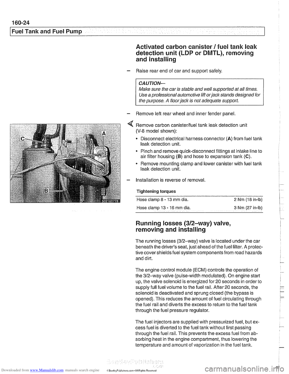
Remove carbon canisterlfuel tank leak detection unit
(V-8 model shown):
Disconnect electrical harness connector
(A) from fuel tank
leak detection unit.
Pinch and remove quick-disconnect fittings at intake line to
air filter housing
(5) and hose to expansion tank (C).
* Remove mounting clamp and lower canister with fuel tank
leak detection unit.
Installation is reverse of removal.
Tightening
torques
Hose clamp 8 - 13 mm dia. 2 Nrn (18 in-lb)
Hose clamp
13 - 16 rnm dia 3 Nm (27 in-lb)
Running losses (312-way) valve,
removing and installing
The running losses (312-way) valve is located under the car
beneath the driver's seat, just ahead of the fuel filter. A protec-
tive covershieldsfuel system components from road hazards
and dirt.
The engine control module
(ECM) controls the operation of
the 312-way valve (pulse-width modulated). On engine start
up, the valve solenoid is energized for 20 seconds in order to
supply full fuel volume to the fuel rail.
After20 seconds, the
solenoid is deactivated and sprung closed (the bypass is
opened). This reduces the amount of fuel circulating through
the fuel rail and diverts the excess to return to the fuel tank
through the fuel pressure regulator.
The fuel injectors are supplied with pressurized fuel, but ex-
cess fuel is diverted to the fuel tank without first passing
through the fuel rail. This prevents the excess fuel from ab-
sorbing heat in the engine compartment, thus lowering the
temperature and amount of vaporization in the fuel tank.
Page 540 of 1002
Downloaded from www.Manualslib.com manuals search engine
This repair group covers general application information for
the clutch, manual and automatic transmissions, shift linkag-
es and driveshaft.
Drivetrain
I ZF manual transmission I
BMW E39 models are equipped with a longitudinal drivetrain.
The transmission is bolted directly to the rear of the engine.
A
driveshaft connects the output shaft of the transmission to the
rear final drive. Individual drive axles with integrated constant
velocity joints transfer rotational power from the final drive
unit to the rear wheels.
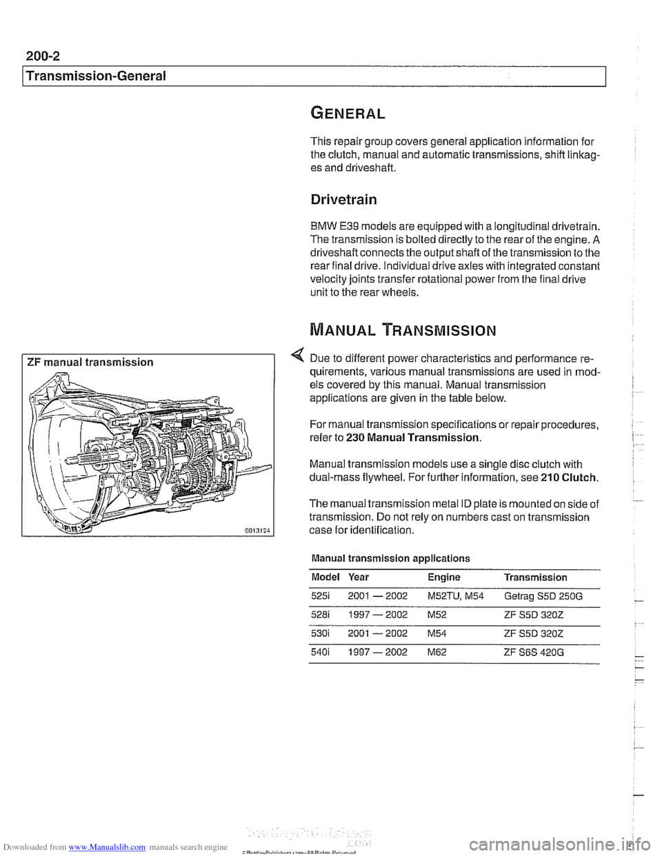
4 Due to different power characteristics and performance re-
quirements, various manual transmissions are used in mod-
els covered by this manual. Manual transmission
applications are given in the table below.
For manual transmission specifications or repair procedures,
refer to
230 Manual Transmission.
Manual transmission models use a single disc clutch with
dual-mass flywheel. For further information, see
210 Clutch.
The manual transmission metal ID plate is mounted on side of
transmission. Do not rely on numbers cast on transmission
case for identification.
Manual transmission applications
Model Year Engine Transmission
5251 2001 - 2002 M52TU, M54 Getrag S5D 250G
528i 1997-2002 M52 ZF S5D 3202
Page 543 of 1002
Downloaded from www.Manualslib.com manuals search engine
210 Clutch
........................... General .21 0.2
........................ Special tools .21 0.2
Clutch Hydraulics ................. .21 0.4
Clutch hydraulic system.
bleeding and flushing
................. .21 0.4
Clutch master cylinder. replacing
........ .21 0.6
Clutch slave cylinder. replacing ......... .21 0.8 Flywheel. removing
and installing
................... (6 cylinder engine) 210-12
Flywheel. removing and installing
(V-8 engine) ....................... 21 0-1 3
Transmission pilot bearing. replacing .... 210-1 5
Clutch. installing (non-SAC components) . 210-1 6
Clutch. installing (new SAC components)
. 21 0-17
Clutch.
install in^ (used SAC components) 210-19
Clutch Mechanical ................. .21 0.9 self-adjusting crutch (SAC). breaking in : . 210-21
..................... Clutch variations .21 0.9
................... Clutch. removing .21 0.1 1
Clutch components. inspecting
........ .21 0.1 1
Page 544 of 1002
Downloaded from www.Manualslib.com manuals search engine
1 Clutch
This repair group covers replacement of clutch mechanical
and hydraulic components.
BMW 5 Series models with manual transmission use a single
disc hydraulically actuated clutch.
Twoversions of the clutch
are used:
1997
5281 (6 cylinder) uses traditional clutch components.
All 540i (V-8) and 1998 and later
6 cylinder models use a
self-adjusting clutch (SAC).
NOTE-
See 200 Transmission-General for transmission applica-
tion information.
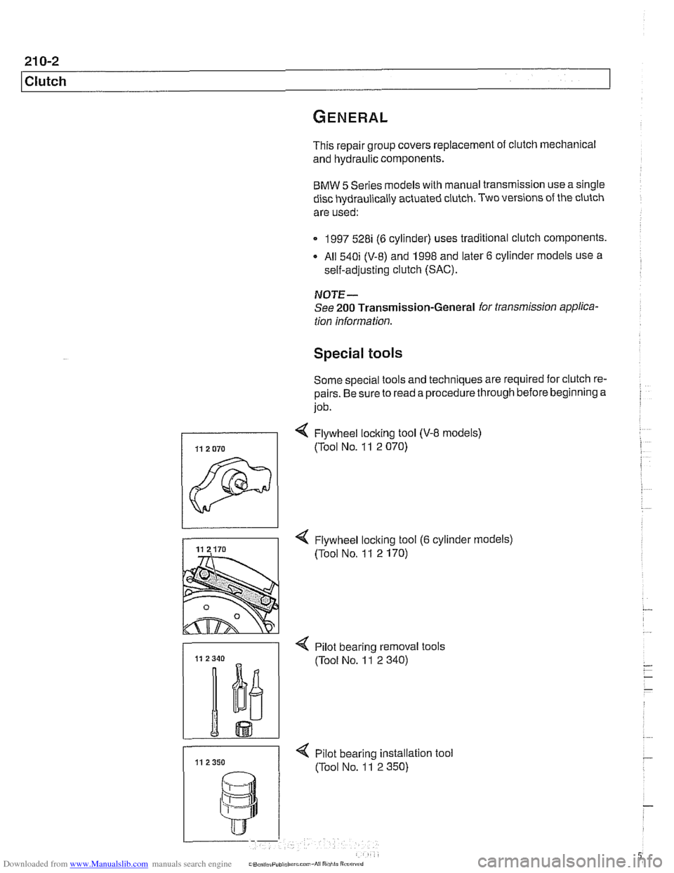
Special tools
Some special tools and techniques are required for clutch re-
pairs. Be sure to read a procedure through before beginning a
job.
< Flywheel loclting tool (V-8 models)
1 (Tool NO. 11 2 070)
-
4 Flywheel loclting tool (6 cylinder models)
(Tool No. 1 1 2 170)
- < Pilot bearino removal tools
11 11 2350 < pilot bearing instaation
(Tool No. 11 2 350) tool