check oil BMW 540i 1998 E39 Manual Online
[x] Cancel search | Manufacturer: BMW, Model Year: 1998, Model line: 540i, Model: BMW 540i 1998 E39Pages: 1002
Page 745 of 1002
Downloaded from www.Manualslib.com manuals search engine
33UFinal Drive
General ........................... ,331 -2 Drive Axles ....................... 331 -1 4
Special tools
........................ ,331 -2 Drive axle assembly ................. 331-14
Aluminum suspension components
...... ,331-4 Drive axle, removing and
installing (sedan)
.................... 331-14 ........................ Final Drive ,331 -5
Drive axle, removing
........... ...... Final drive, removing and installing ,331-5 and (Sport Wagon) 331-15
...................... Differential oil level, checking ........... ,331-6 CV joint boots 331-17 Final drive in~ut shaft seal, replacing ..... ,331-7 .
Final drive oitput shaft seals, replacing . . ,331-10
Final drive cover, removing and installing ,331-12
Final drive mounts, replacing .......... ,331-12
Page 749 of 1002
Downloaded from www.Manualslib.com manuals search engine
Final Drive
Final drive, removing and installing
- Raise rear of car.
WARNING-
Make sure that the car is firmly supported on jack stands de-
signed for the purpose. Place the jaclc stands beneath struc-
tural chassis
~oints. Do not i lace iaclc stands under
( suspension barfs.
Remove exhaust system. See 180 Exhaust System.
Disconnect drive shaft from final drive. See
260 Driveshaft.
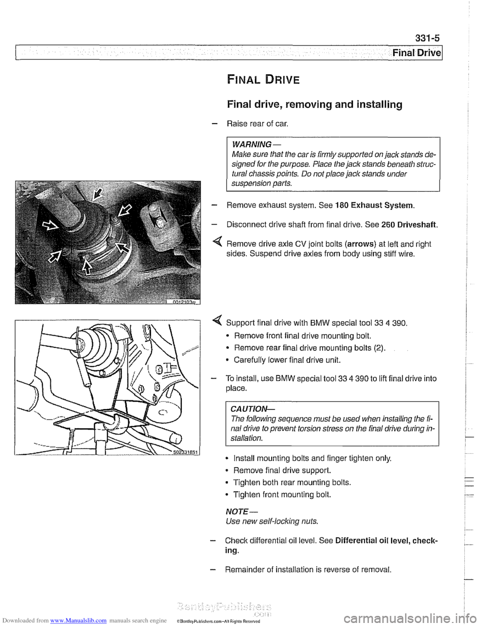
Remove drive axle CV joint bolts (arrows) at left and right
sides. Suspend drive axles from body using stiff wire.
4 Support final drive with BMW special tool 33 4 390.
* Remove front final drive mounting bolt.
Remove rear final drive mounting bolts
(2).
Carefully lower final drive unit.
- To install, use BMW special tool 33 4 390 to lift final drive into
place.
CA UTIOP&
The following sequence must be used when installing the fi-
nal drive to prevent torsion stress on the final drive during in-
Install mounting bolts and finger tighten only.
Remove final drive support.
Tighten both rear mounting bolts.
Tighten front mounting bolt.
NOTE-
Use new self-locking nuts.
- Check differential oil level. See Differential oil level, check-
ing.
- Remainder of installation is reverse of removal.
Page 750 of 1002
Downloaded from www.Manualslib.com manuals search engine
Final Drive
Tightening torques
F~nal drive to rear axle carrier 105 Nm (77 it-lb)
Driveshaft CV joint to final drive flange
- MlO (Torx bolt) 70
Nm (51 ft-lb)
- M8 (compression nut) 32 Nm (24
ft-lb)
Drive axle to final drive
ilange
Torx bolts (M10) 83 Nm (61 ft-lb)
Torx bolt with
rlbbed teeth (M10) 64 Nm (47 ft-lb)
Torx bolt
wlth ribbed teeth (MI0 sliver) 80 Nm (59 ft-lb)
Torx
bolt with ribbed teeth (M10 black) 100 Nm (74 ft-lb)
* Torx bolt with ribbed teeth (M12) 135 Nm (100 ft-lb)
Differential oil level, checking
The E39 differential is filled with lifetime oil that ordinarily
does not need to be changed. BMW recommends using only
a specially formulated synthetic gear oil
(SAF-XO) that is
available through an authorized BMW dealer parts depart-
ment. For additional information on this lubricant and any oth-
er lubricants that may be compatible, contact an authorized
BMW dealer service department.
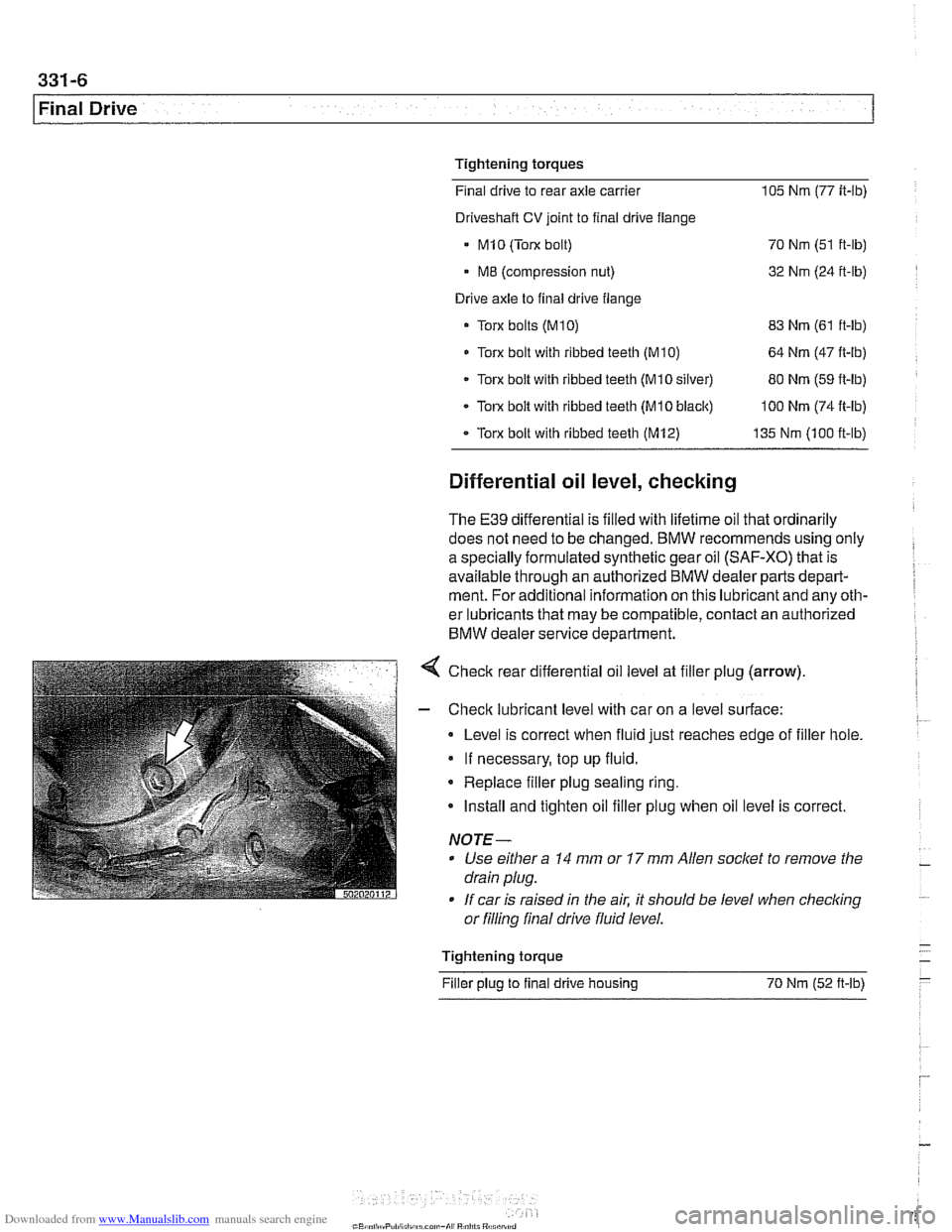
< Check rear differential oil level at filler plug (arrow).
- Check lubricant level with car on a level surface:
Level is correct when fluid just reaches edge of filler hole.
If necessary, top up fluid.
* Replace filler plug sealing ring.
Install and tighten oil filler plug when oil level is correct.
NOTE-
Use either a 14 mm or 17 mm Allen socket to remove the
drain plug.
If car is raised in the air. it should be level when
checkino " or filling final drive fluid level.
- Tightening torque -
Filler plug to final drive housing 70 Nm (52
ft-lb) -
Page 753 of 1002
Downloaded from www.Manualslib.com manuals search engine
331-9
Final Drive
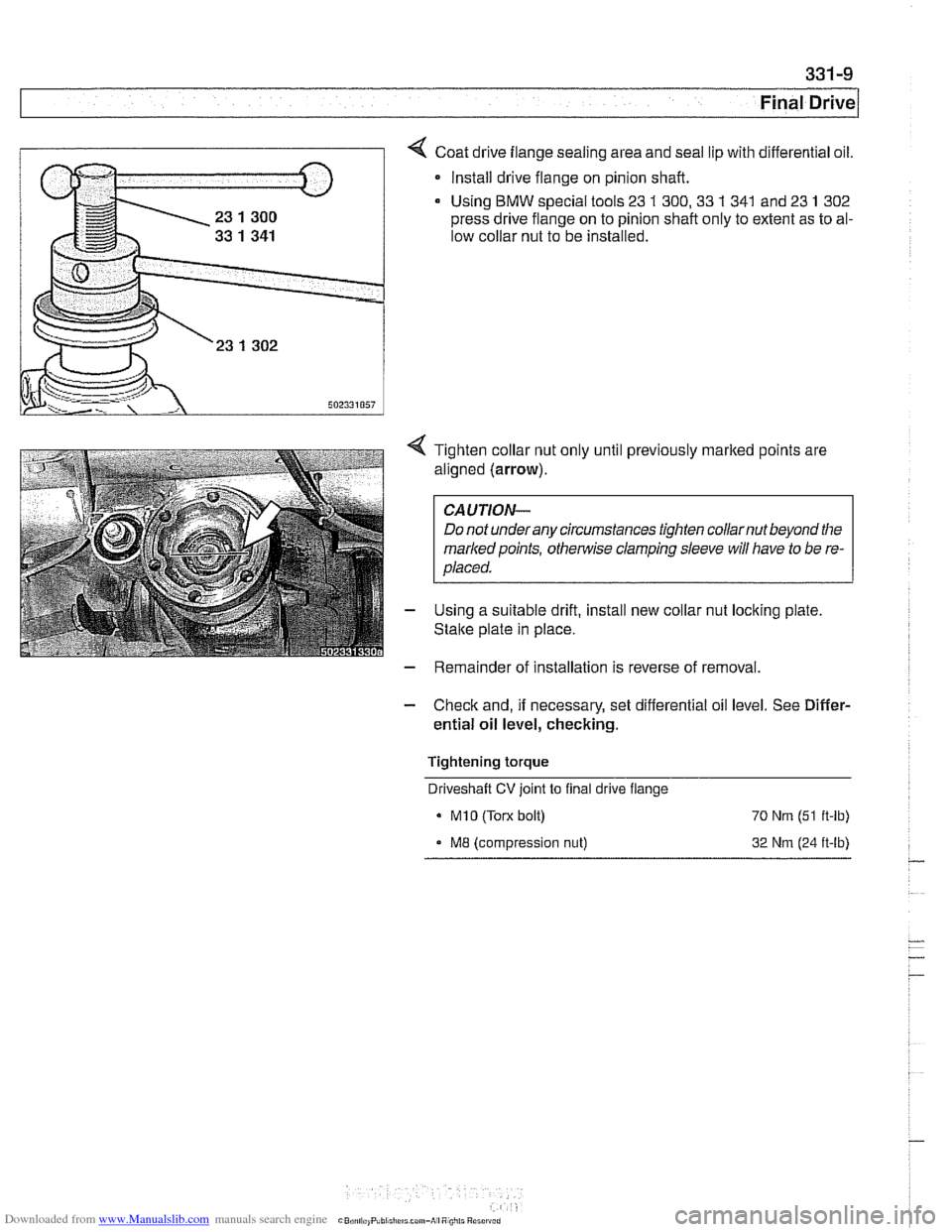
Coat drive flange sealing area and seal lip with differential oil.
* Install drive flange on pinion shaft.
Using
BMW special tools 23 1 300,33 1 341 and 23 1 302
press drive flange on to pinion shaft only to extent as to al-
low collar nut to be installed.
4 Tighten collar nut only until previously marked points are
aligned (arrow).
CAUTION-
Do not underany circumstances tighten collarnut beyond the
markedpoints,
othe~lise clamping sleeve will have to be re-
placed.
- Using a suitable drift, install new collar nut locking plate
Stalte plate in place.
- Remainder of installation is reverse of removal.
- Check and, if necessary, set differential oil level. See Differ-
ential oil level, checking.
Tightening torque Driveshaft
CV joint to final drive flange
MI0 (Torx bolt) 70 Nrn (51 ft-lb)
ME (compression nut) 32 Nrn (24 ft-lb)
Page 755 of 1002
Downloaded from www.Manualslib.com manuals search engine
331-1 1
Final rive(
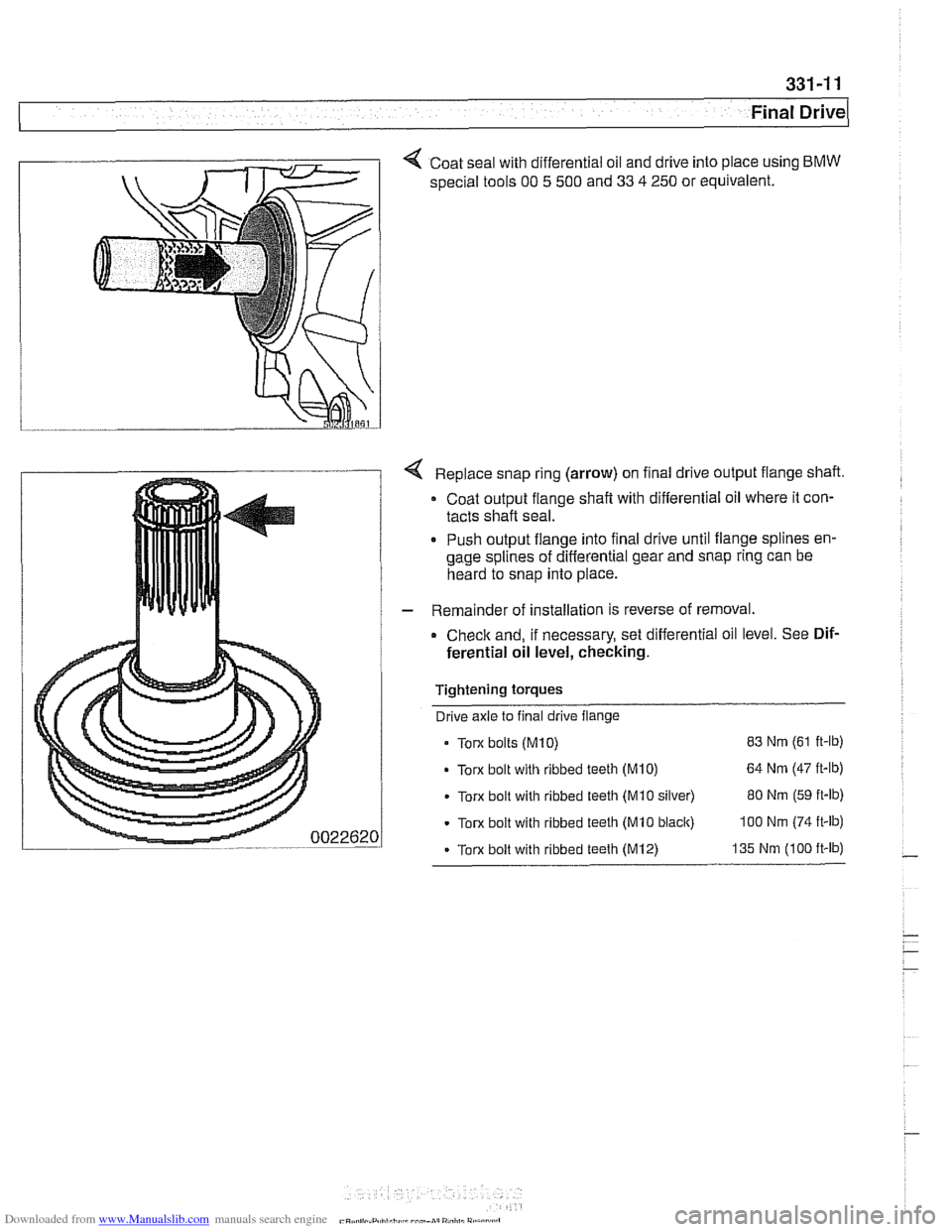
< Coat seal with differential oil and drive into place using BMW
special tools 00 5 500 and 33 4 250 or equivalent.
Replace snap ring (arrow) on final drive output flange shaft.
Coat output flange
shaft with differential oil where it con-
tacts shaft seal.
. Push output flange into final drive until flange splines en-
gage splines of differential gear and snap ring can be
heard to snap into place.
- Remainder of installation is reverse of removal.
Check and, if necessary, set differential oil level. See Dif-
ferential oil level, checking.
Tightening torques Drive axle to final drive flange
Torx bolts
(M10) 83 Nm (61 ft-lb)
Torx bolt with ribbed teeth (M10) 64 Nm (47 it-lb)
Torx bolt with ribbed teeth (Mi0 silver) 80 Nm (59 ft-lb)
Torx bolt with ribbed teeth (MI0 black) 100 Nm (74 ft-lb)
- Torx bolt with ribbed teeth (M12) 135 Nm (100 ft-lb)
Page 756 of 1002
Downloaded from www.Manualslib.com manuals search engine
331-12
Final Drive Final drive cover, removing and installing
- Remove final drive. See Final drive, removing and install-
ing.
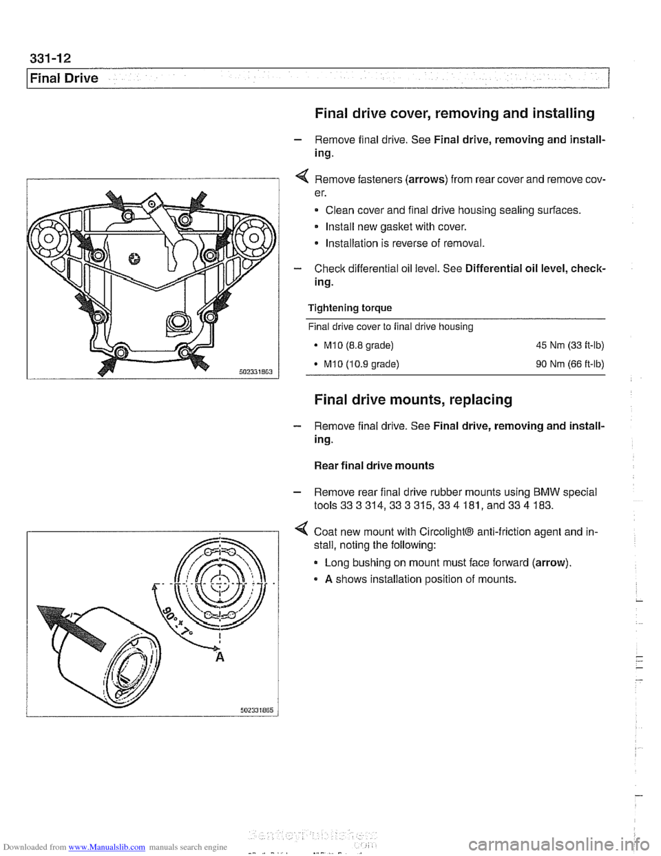
I 1 4 Remove fasteners (arrows) from rear cover and remove cov-
er.
Clean cover and final drive housing sealing surfaces.
Install new
gasket with cover.
* Installation is reverse of removal.
- Check differential oil level. See Differential oil level, check-
ing.
Tightening
torque
Final drive cover to final drive housing
. M10 (8.8 grade) 45 Nm (33 ft-lb)
M10 (10.9 grade) 90 Nm (66 ft-lb)
Final drive mounts, replacing
- Remove final drive. See Final drive, removing and install-
ing.
Rear final drive mounts
- Remove rear final drive rubber mounts using BMW special
tools333314,333315,334 181, and334 183.
4 Coat new mount with CircolightB anti-friction agent and in-
.
stall, noting the following:
Long bushing on mount must face forward (arrow).
A shows installation position of mounts.
Page 768 of 1002
Downloaded from www.Manualslib.com manuals search engine
340-6
1 Brakes
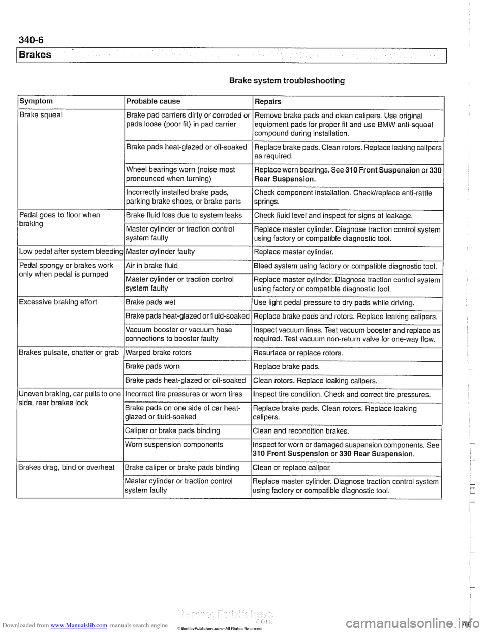
Brake system troubleshooting
/symptom I Probable cause 1 Repairs
Brake squeal
Pedal goes to floor when
bralting
Low pedal after system bleeding
Pedal spongy or brakes work
only when pedal is pumped
Excessive braking effort
Brakes pulsate, chatter or grab
Uneven
bralting, car pulls to one
side, rear braltes
loclt
Brakes drag, bind or overheat Brake
pad carriers dirty or corroded or
pads loose (poor fit) in pad carrier
Braite pads heat-glazed or oil-soaked
Wheel bearings worn (noise most
pronounced when turning)
Incorrectly Installed brake pads,
parking bralte shoes, or bralte parts
Brake fluid loss due to system leaks
Master cylinder or traction control
system faulty
Master cylinder faulty
Air in braite fluid
Master cylinder or traction control
system faulty
Brake pads wet
Brake pads
heat-glazedorfluid-soalted
Vacuum booster or vacuum hose
connections to booster faulty
--- Warped brake rotors
Brake pads worn
Brake pads heat-glazed or oil-soaked Remove
brake pads and clean calipers. Use original
equipment pads for proper fit and use BMW anti-squeal
compound during installation,
Replace brake pads. Ciean rotors. Replace leaking caliper:
as required.
Replace worn bearings. See 310 Front Suspension
or33C
Rear Suspension.
Check component installation. Checldreplace anti-rattle
springs.
Checlt fluid level and inspect for signs of leakage.
Replace master cylinder. Diagnose traction control system
using factory or compatible diagnostic tool.
Replace master cylinder.
Bleed system using factory or compatible diagnostic tool.
Replace master cylinder. Diagnose traction control system
using factory or compatible diagnostic tool.
Use light pedal pressure to dry pads while driving.
Replace
bralte pads and rotors. Replace leaking calipers.
lnspect vacuum lines. Test vacuum booster and replace as
required. Test vacuum non-return valve for one-way flow.
Resurface or replace rotors.
Replace brake pads.
Clean rotors. Replace leaiting calipers.
Incorrect tire pressures or worn tires
Brake pads on one side of car heat-
glazed or fluid-soaked
Caliper or brake pads binding
Worn suspension components
Brake caliper or brake pads binding
Master cylinder or traction control
system faulty lnspect
tire condition. Checlt and correct tire pressures.
Replace brake pads. Clean rotors. Replace leaking
calipers.
Clean and recondition brakes.
Inspect for worn or damaged suspension components. See
310 Front Suspension or 330 Rear Suspension.
Ciean or replace caliper.
Replace master cylinder. Diagnose traction control system
using faclory or compatible diagnostic tool.
Page 975 of 1002
Downloaded from www.Manualslib.com manuals search engine
OBD-15
On-Board ~iagnosticsl
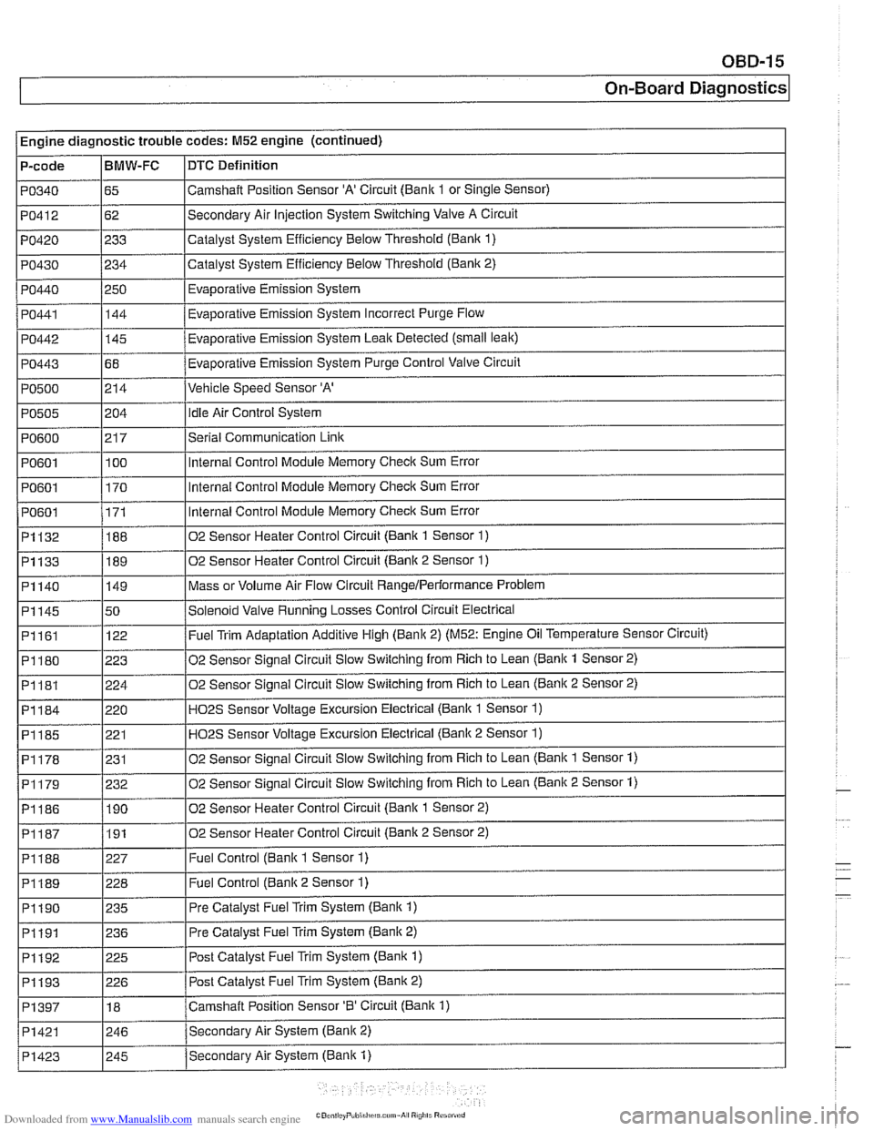
Engine diagnostic trouble codes: M52 engine (continued)
P-code
PO340
PO412
PO420
PO430
PO440
PO441
PO442
PO443
PO500
PO505
PO600
PO601
PO601
I PO601
~1132
~1133
BMW-FC
65
62
233
234
250 144
-
145
68
214
i I
DTC Definition
Camshalt Position Sensor 'A' Circuit (Bank 1 or Single Sensor)
Secondary Air Injection System Switching Valve A Circuit
Catalyst System Efficiency Below Threshold
(Bank 1)
Catalyst System Efficiency Below Threshold (Bank 2)
Evaporative Emission System
Eva~orative Emission Svstem Incorrect Purge Flow .
Evaporative Emission System Leak Detected (small leak)
Evaporative Emission System Purge Control Valve Circuit
Vehicle Speed Sensor 'A'
204
21 7
100
170
171
188
189
PI161
PI180
PI181
PI184
PI185
PI178
02 Sensor Heater Control Circuit (Bank 2 Sensor 2) I
idle Air Control System
Serial Communication
Link
Internal Control Module Memory Check Sum Error
Internal Control Module Memory
Check Sum Error
Internal Control Module Memory
Check Sum Error
02 Sensor Heater Control Circuit (Bank 1 Sensor
1)
02 Sensor Heater Control Circuit (Bank 2 Sensor 1)
Mass or Volume Air Flow Circuit RangeIPerlormance Problem PI140
I
I I
P1188 1227 I Fuel Control (Bank 1 Sensor 1)
PI145 150 /Solenoid Valve Running Losses Control Circuit Electrical
149
122
223
224
220 221
231
I I
P1189 1228 I Fuel Control (Banlc 2 Sensor 1)
Fuel Trim Adaptation Additive High (Bank 2) (M52: Engine Oil Temperature Sensor Circuit)
02 Sensor Signal Circuit Slow Switching from Rich to Lean
(Bank 1 Sensor 2)
02 Sensor Signal Circuit Slow Switching from Rich to Lean
(Bank 2 Sensor 2)
H02S Sensor Voltage Excursion Electrical (Banlc 1 Sensor 1)
HO2S Sensor Voltage Excursion Electrical (Banlc 2 Sensor 1)
02 Sensor Sianai Circuit Slow Switchina from Rich to Lean (Bank 1 Sensor 1)
02 Sensor Signal Circuit Slow Switching from Rich to Lean (Bank 2 Sensor 1) PI179
I I
PI190 1235 I Pre Catalyst Fuel Trim System (Banlc 1)
PI186 1190 102 Sensor Heater Control Circuit (Banlc 1 Sensor 2)
232
I I
PI191 1236 I Pre
Catalyst Fuel Trim System (Banlc 2)
PI192
. . -- - i Pi193 1226 I Post Catalvst Fuel Trim Svstem (Bank 2)
225
PI397
I I
Post Catalyst Fuel Trim System (Bank 1)
PI421 1246 /Secondarv Air System (Bank 2)
18
Secondary Air System (Bank
1) PI423
Camshaft Position Sensor '0' Circuit (Bank 1)
I 245
Page 993 of 1002
Downloaded from www.Manualslib.com manuals search engine
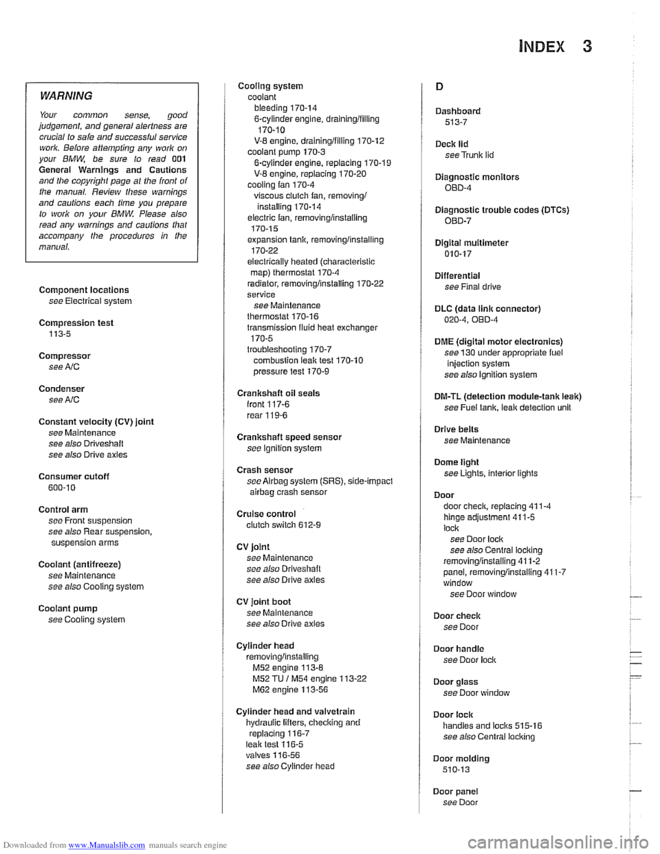
WARNING
Your common sense, good
judgement, and general alertness are
crucial lo sale and
successlul service
work. Belore attempling any work on
your BMW, be sure to read 001
General Warnings and Cautions
and lhe copyright page
a1 llle Iron1 01
the manual. Review lliese warnings
and cautions each time you prepare
lo work on your
BMW Please also
read any warnings and
caulions lhal
accompany the procedures In !he
manual.
Component locations
see Electrical system
Compression test
113-5
Compressor see
AlC
Condenser see
AlC
Constant velocity (CV) joint
see Maintenance
see also
Driveshall
see also Drive axles
Consumer cutoff
600-10
Control arm see Front suspension
see also Rear suspension,
suspension arms
Coolant (antifreeze) see Maintenance
see also Cooling system
Coolant pump
see Cooling system Cooling system
coolant bleeding
170-14 6-cylinder engine, draininglfilling
170-10
V-8 engine, draininglfilling 170-12
coolant pump 170-3
6-cyiinder engine, replacing 170-1 9
V-8 engine, replacing 170-20 cooling fan 170-4
viscous ciutch fan, removingi
installing 170-14
electric fan, removlngiinstailing 170-1 5
expansion tank, removinglinstalling
170-22
electrically heated (ciiaracterislic
map) therrnostat 170-4
radiator, removinglinstaliing 170-22
service
see Maintenance
therrnostat 170-16
transmission fluid heat exchanger
170-5 troubleshooting 170-7
combuslion leal( test 170-10
pressure test
170-9
Crankshaft oil seals
iront
117-6
rear 11 9-6
Crankshaft speed sensor
see Ignition syslem
Crash sensor
see
Airbag system (SRS), side-impact
airbag crasii sensor
Cruise control clutch switch 612-9
CV joint
see Maintenance
see also Driveshalt
see also Drive axles
CV joint boot
see Maintenance
see also Drive axles
Cylinder head removinglinslaliing
M52 engine 113-8
M52 TU / M54 engine 113-22
M62 engine 113-56
Cylinder head and valvetrain
hydraulic lifters, checking and
replacing
116-7 leak test 116-5 valves 11 6-56
see
alsocylinder head Dashboard
513-7
Deck
lid
seeTrunk lid
Diagnostic monitors
OED-4
Diagnostic trouble codes
(DTCs)
080-7
Digital multimetel
010-17
Differential see Final drive
DLC (data
link connector) 020-4, OED-4
DME (digital motor electronics)
see
130 under appropriate fuel
injection system
see also ignition system
DM-TL (detection module-tank leak)
see
Fuel lank, leak deteclion unit
Drive
belts
see Maintenance
Dome light
seeLighls, interior lights
Door
door
check, replacing 411-4
hinge adjustment 41 1-5
loci(
see Door lock see also Central locking
removinglinslaliing 41
1-2
panel, removinglinstaliing 41 1-7 window
see Door window
Door
check
see Door
Door
handle
see Door lock
Door glass
see Door window
Door
lock
handles and loci(s 515-16
see also Central locking
Door
molding
510-13
Door panel see Door
Page 996 of 1002
Downloaded from www.Manualslib.com manuals search engine
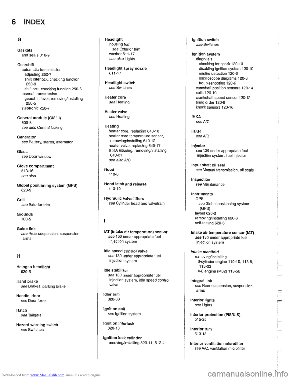
Gaskets and seals 01
0-9
Gearshift automatic transmission
adjusting
250-7
shift interiock. checkino function " 250-9
shiftloclc. checicino function 250-8 - manual transmission
gearshift lever, removingiinstalling
250-5
steptronic 250-7
General module (GM Ill)
600-8
see also Central locking
Generator see Battery, starter, alternator
Glass see Door window
Glove compartment
513-16
see also
Global positioning system
(GPS)
620-9
Grill
see Exterior trim
Grounds
100-5
Guide link
see Rear suspension, suspension
arms
Halogen headlight
630-5
Hand brake
see Brakes, pariring brake
Handle, door
see Door
locks
Hatch seeTailgate
Hazard warning switch
see Switches Headlight
housing trim
see Exterior trim
washer611-17 see also Lights
Headlight spray
nozzle
611-17
Headlight switch
see Switches
Heater core
see Heating
Heater valve
see Heating
Heating lieater core, replacing
640-18
lheater core temperature sensor,
removingiinstalling
640-12 heater valve, replacing 640-17
IHKA housing, removinglinstallin~
640-21
see also NC
Hood
410-6
Hood latch and release
410-10
Hydraulic valve lifters
see Cylinder head and valvetrain
IAT
(lntalce air temperature) sensor
see 130
under appropriate fuel
injection system
idle speed control valve
see 130
under appropriate fuel injection system
Idle stabilizer
see 130
under appropriate fuel
injection system, idie speed controi
valve
idler arm
320-30
lgnition coll
see lgnition system
lgnition interlock
320-13
lgnition lock cylinder
removingiinstalling
320-1 1. 612-4
lgnition switch
seeSwifches
Ignition system
diagnosis checking for
spark 120-10
disabling ignition system 120-10 misfire detection 120-6
oscilioscope diagrams 120.6
troubleshooting 120-6
camshaft position sensors 120-14 coils 120.10
crankshaft speed sensor 120-12 firing order 120-9
knoclc sensors 120-16
IHKA
see NC
IHKR see NC
Injector
see 130 under appropriate
fuel
injection system, luel injector
Input shaft
oil seal
see Manual transmission, oil seals
Inspection
see Maintenance
Instruments GPS see Global positioning system
(GPSI layout 6202
removingiinstalling 620-8 self-testing 620-6
Intake air temperature sensor (IAT)
see 130 under appropriate fuel
injection system
Intake manifold
removingiinstalling
6-cvlinder enoine 110-10. 113-8. 113-22 -
V-8 engine (M62) 113-56
Integral link
see Rear suspension, suspension
arms
lnterior lights
see Lights
lnterior protection
(FISIUIS) 515-25
lnterior trim
513-13
lnterior ventilation microfilter see
NC, ventilation microfiller