Controls BMW 540i 1998 E39 Workshop Manual
[x] Cancel search | Manufacturer: BMW, Model Year: 1998, Model line: 540i, Model: BMW 540i 1998 E39Pages: 1002
Page 405 of 1002
Downloaded from www.Manualslib.com manuals search engine
Fuel injectors, checking and replacing
The fuel injectors are electronically controlled solenoid valves
that provide precisely metered and atomized fuel into the en-
gine intake ports.
The injectors receive voltage from the ECM relay. The ECM
controls the opening by activating the ground circuit
forthe in-
jector valve solenoids. The ECM varies the duration (in milli-
seconds) of "opening" time to regulate the
airlfuel ratio.
For a quick
check of the injectors, run the engine and touch
each injector with a screwdriver or stethoscope. You should
feel a vibration or hear a buzzing
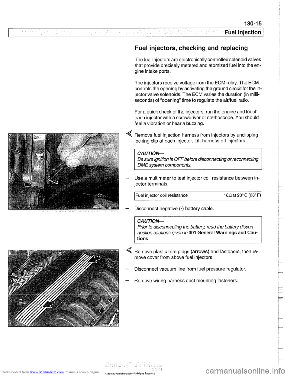
Remove fuel injection harness from injectors by unclipping
locking clip at each injector. Lift harness off injectors.
CA U JIOG
Be sure ignition is OFF before disconnecting or reconnecting
DME system components.
Use a multimeter to test injector coil resistance between in-
jector terminals.
l~uel injector coil resistance 16R at 20" C (68" F)
Disconnect negative
(-) battery cable
CAUTIOG
Prior to disconnecting the battery, read the battery discon-
nection cautionsgiven
in 001 General Warnings and Cau-
tions.
4 Remove plastic trim plugs (arrows) and fasteners, then re.
move cover from above fuel injectors.
- Disconnect vacuum line from fuel pressure regulator.
- Remove wiring harness duct mounting fasteners.
Page 407 of 1002
Downloaded from www.Manualslib.com manuals search engine
Fuel Injection 1
NOTE-
The 1998 5281' with MS 41.1 requires a barometric pressure
sensor input signal for activation of the
LDP check. This sen-
sor is located on the passenger side strut tower
fo~lard of
ABS/ASC hydraulic unit.
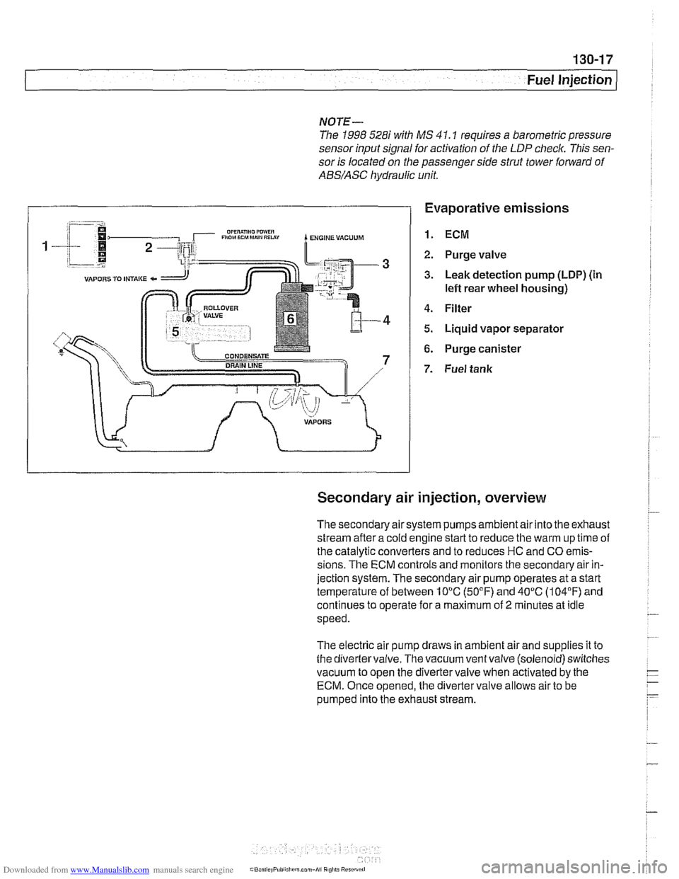
Evaporative emissions
1. ECM
2. Purge valve
3. Leak detection pump (LDP) (in
lefl rear wheel housing)
4. Filter
5. Liquid vapor separator
6. Purge canister
7. Fuel tank
Secondary air injection, overview
The secondary air system pumps ambient air into the exhaust
stream afler a cold engine start to reduce the warm up time of
the catalytic converters and to reduces HC and CO emis-
sions. The ECM controls and monitors the secondary air in-
jection system. The secondary air pump operates at a start
temperature of between 10°C (50°F) and 40°C (104°F) and
continues to operate for a maximum of
2 minutes at idle
speed.
The electric air pump draws in ambient air and supplies it to
the divertervalve. The vacuum ventvalve (solenoid) switches
vacuum to open the divertervalve when activated by the
ECM. Once opened, the diverter valve allows air to be
pumped into the exhaust stream.
Page 414 of 1002
Downloaded from www.Manualslib.com manuals search engine
Fuel Injection
- Ignition:
Direct ignition
Knock control
4 Primary1 secondary ignition monitoring
- Emissions:
OBD II compliance
Secondary air injection
Pre- and post-catalyst oxygen sensors
0 Electrically heated DME-mapped thermostat
Misfire detection
Evaporative emission control and
leak detection
Malfunction indicator light (MIL)
Performance controls:
Dual VANOS control
Output of injection signal (TI) for fuel economy gauge
Output of engine rpm (TD) for tachometer
AIC compressor control
0 Electric radiator cooling fan
CAN-Bus communication
Stability and traction system
(ABSIASCIDSC) interlace
Electronic immobilizer (EWS)
Cruise control
ECM programming
Page 447 of 1002
Downloaded from www.Manualslib.com manuals search engine
Fuel Injection
Intake air temperature
([AT) sensor,
testing and replacing
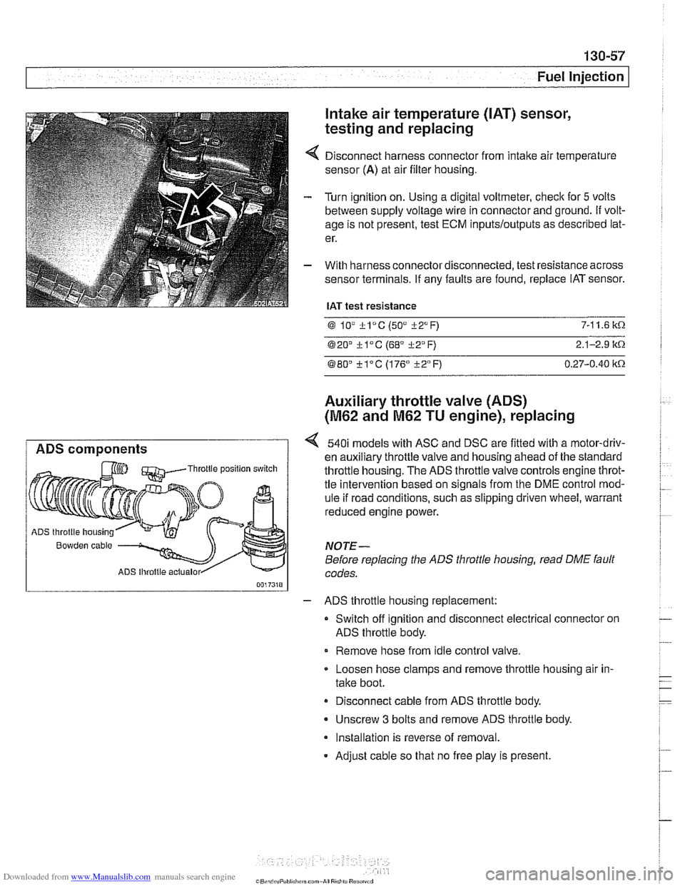
Disconnect harness connector from intake air temperature
sensor
(A) at air filter housing.
Turn ignition on. Using a digital voltmeter, check for
5 volts
between supply voltage wire in connector and ground.
If volt-
age is not present, test ECM
inputs/outputs as described lat-
er.
With harness connector disconnected, test resistance across
sensor terminals. If any faults are found, replace IAT sensor.
IAT test resistance
0 lV *lac (50" i-2°F) 7-1 1.6 k.0.
020' kl°C (68' 322°F) 2.1-2.9 it.0.
080" ?lac (176" i-2°F) 0.27-0.40 itn
Auxiliary throttle valve (ADS)
(M62 and M62 TU engine), replacing
ADS components 540i models with ASC and DSC are fitted with a motor-driv-
en auxiliary throttle valve and housing ahead of the standard Throttle position switch throttle housing. The ADS throttle valve controls engine throt-
tle intervention based on signals from the DME control mod-
ule if road conditions, such as slipping driven wheel, warrant
reduced engine power.
ADS throttle housing
Bowden cable NOTE-
Before replacing the ADS throttle housing, read DME fault
ADS lhroltle actualor codes.
- ADS throttle housing replacement:
Switch off ignition and disconnect electrical connector on
ADS throttle body.
Remove hose from idle control valve.
Loosen hose clamps and remove throttle housing air in-
take boot.
Disconnect cable from ADS throttle body.
- Unscrew 3 bolts and remove ADS throttle body.
Installation is reverse of removal.
- Adjust cable so that no free play is present.
Page 465 of 1002
Downloaded from www.Manualslib.com manuals search engine
130-75
Fuel Injection
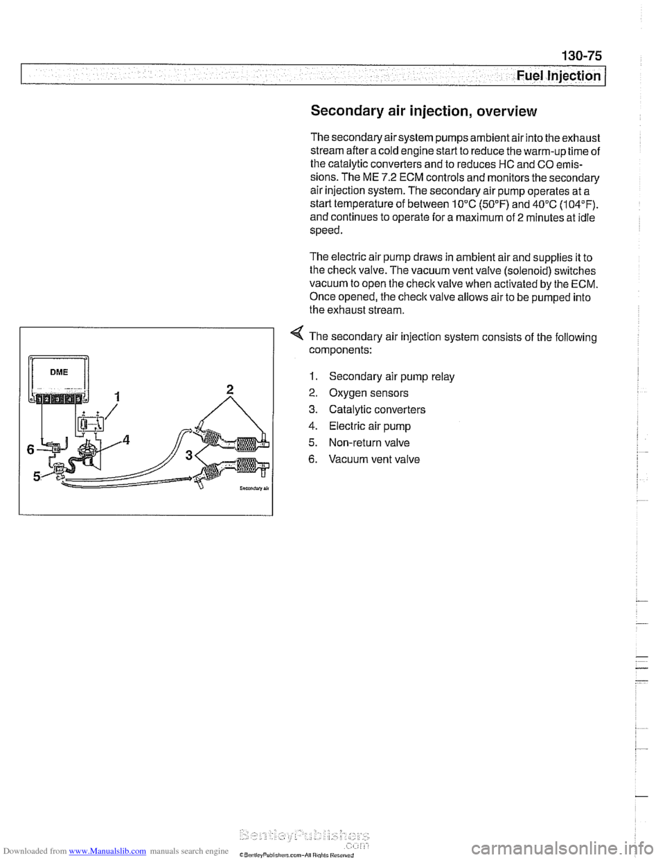
Secondary air injection, overview
The secondary air system pumps ambient air into the exhaust
stream afteracoid engine start to reduce the warm-up time of
the catalytic converters and to reduces HC and CO emis-
sions. The ME
7.2 ECM controls and monitors the secondary
air injection system. The secondary air pump operates at a
starttemperature of between 10°C
(50°F) and 40°C (104°F).
and continues to operate for a maximum of
2 minutes at idle
speed.
The electric air pump draws in ambient air and supplies it to
the
checlc valve. The vacuum vent valve (solenoid) switches
vacuum to open the
checlc valve when activated by the ECM.
Once opened, the checlc
valve allows air to be pumped into
the exhaust stream.
4 The secondary air injection system consists of the following
components:
1. Secondary air pump relay
2. Oxygen sensors
3. Catalytic converters
4. Electric air pump
5. Non-return valve
6. Vacuum vent valve
Page 494 of 1002
Downloaded from www.Manualslib.com manuals search engine
Fuel Tank and Fuel Pump 1
Activated carbon canister I fuel tank leak
detection unit
(LDP or DMTL), removing . . -
and installing
- Raise rear end of car and support safely.
CAUTION-
Make sure the car is stable and well supported at all times.
Use a professional automotive lift
orjack stands designed for
the purpose.
A floor jack is not adequate support.
- Remove left rear wheel and inner fender panel
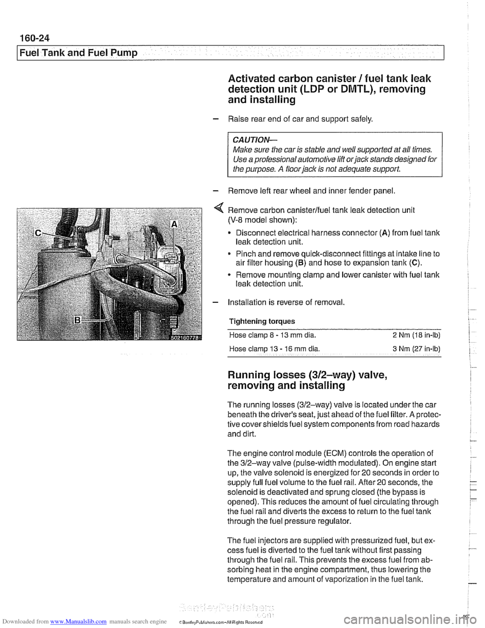
Remove carbon canisterlfuel tank leak detection unit
(V-8 model shown):
Disconnect electrical harness connector
(A) from fuel tank
leak detection unit.
Pinch and remove quick-disconnect fittings at intake line to
air filter housing
(5) and hose to expansion tank (C).
* Remove mounting clamp and lower canister with fuel tank
leak detection unit.
Installation is reverse of removal.
Tightening
torques
Hose clamp 8 - 13 mm dia. 2 Nrn (18 in-lb)
Hose clamp
13 - 16 rnm dia 3 Nm (27 in-lb)
Running losses (312-way) valve,
removing and installing
The running losses (312-way) valve is located under the car
beneath the driver's seat, just ahead of the fuel filter. A protec-
tive covershieldsfuel system components from road hazards
and dirt.
The engine control module
(ECM) controls the operation of
the 312-way valve (pulse-width modulated). On engine start
up, the valve solenoid is energized for 20 seconds in order to
supply full fuel volume to the fuel rail.
After20 seconds, the
solenoid is deactivated and sprung closed (the bypass is
opened). This reduces the amount of fuel circulating through
the fuel rail and diverts the excess to return to the fuel tank
through the fuel pressure regulator.
The fuel injectors are supplied with pressurized fuel, but ex-
cess fuel is diverted to the fuel tank without first passing
through the fuel rail. This prevents the excess fuel from ab-
sorbing heat in the engine compartment, thus lowering the
temperature and amount of vaporization in the fuel tank.
Page 500 of 1002
Downloaded from www.Manualslib.com manuals search engine
-
I Radiator and Cooling System
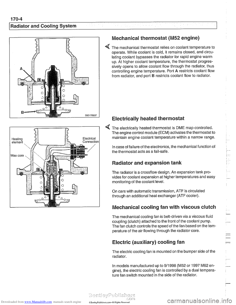
Mechanical thermostat
(M52 engine)
4 The mechanical thermostat relies on coolant temperature to
operate. While coolant is cold, it remains closed, and circu-
lating coolant bypasses the radiator for rapid engine warm
up. At higher coolant temperature, the thermostat progres-
sively opens to allow coolant flow through the radiator, thus
controlling engine temperature. Port
A restricts coolant flow
from radiator, and port
B restricts coolant flow to radiator.
Electrically heated thermostat
4 The electrically heated thermostat is DME map-controlled.
The engine control module (ECM) activates the thermostat to
maintain engine coolant temperature within a narrow range.
In case of failure of the electronics, the mechanical function of
the thermostat acts as a fail-safe.
Radiator and expansion tank
The radiator is a crossflow design. An expansion tank pro-
vides for coolant expansion at higher temperatures and easy
monitoring of the coolant level.
On cars with automatic transmission, ATF is circulated
through an additional heat exchanger (ATF cooler).
Mechanical cooling fan with viscous clutch
The mechanical cooling fan is belt-driven via a viscous fluid
coupling (clutch) attached to the front of the coolant pump.
The fan clutch controls the speed of the fan based on the tem-
perature of the air flowing through the radiator core.
Electric (auxiliary) cooling fan
The electric cooling fan is mounted on the bumper side of the
radiator.
In models manufactured up to
911 998 (M52 or 1997 M62 en-
gine), the electric cooling fan is controlled by a dual tempera-
ture fan switch mounted in the side of the radiator.
Page 506 of 1002
Downloaded from www.Manualslib.com manuals search engine
170-1 0
I Radiator and Cooling System
Combustion chamber leak test
- If you suspect that combustion chamber pressure is leaking
into the cooling system past the cylinder head gasket, use an
exhaust gas analyzer to test the vapors rising from the cool-
ant at the expansion tank.
CAUTIO&
Use an extension tube above the reservoir neclc to main-
tain distance between the top of the coolant and the gas
analyzer
nozzle. The gas analyzer is easily damaged if it is
allowed to inhale liquid coolant.
* While running engine to checlc for causes of overheat-
ing, observe coolant temperature carefully in order to
avoid engine damage.
Thermostat
If the engine overheats or runs too cool and no other cooling
system tests indicate trouble, the thermostat may be faulty.
In
V-8 models and 6-cvlinder models nroduced afler 911 998
(M52TU or M54 eng'ne), rheelecrricaily heated rhermostal IS
mon tored by [he OBD II diagnostlc software The fault may ic
in the DME software or hardware, or it may lie in the wiring to
the thermostat. See
OED On-Board Diagnostics.
Coolant, draining and filling
(6-cylinder models)
WARNING -
Allow the cooling system to cool before opening or draining
the cooling system.
- Raise front of car and support safely.
WARNING -
Make sure the car is stable and well supported at all times.
Use a professional automotive lift
orjack stands designed for
the purpose. A floor jack is not adequate support.
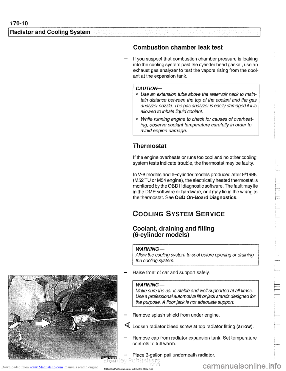
- Remove splash shield from under engine.
4 Loosen radiator bleed screw at top radiator fitting (arrow).
- Remove cap from radiator expansion tank. Set temperature
controls to
full warm.
gallon pail underneath radiator.
Page 507 of 1002
Downloaded from www.Manualslib.com manuals search engine
170-1 1
Radiator and Cooling system/
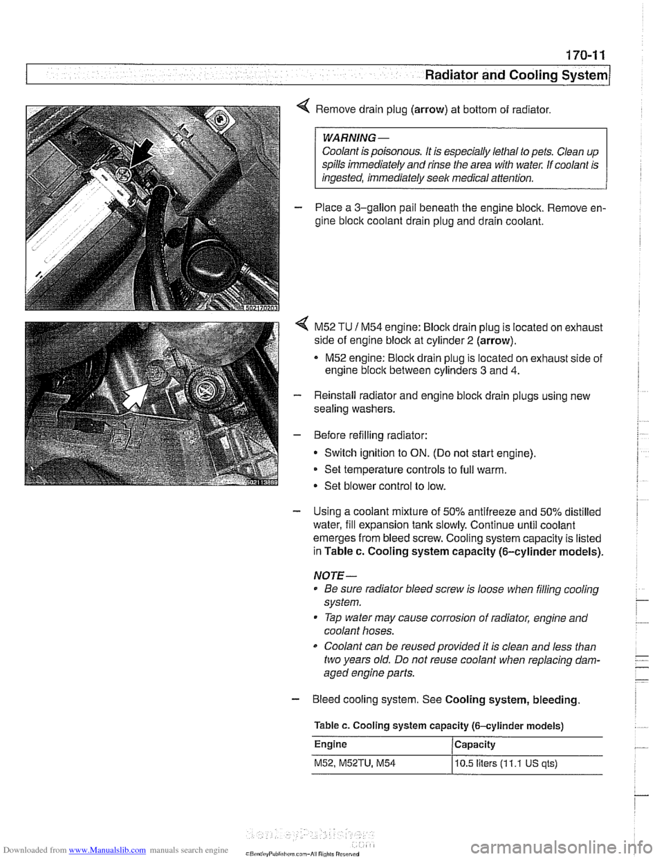
4 Remove drain plug (arrow) at bottom of radiator.
Coolant is poisonous. It is especially lethal to pets. Clean up
spills immediately and rinse the area with
wate,: If coolant is
- Place a 3-gallon pail beneath the engine block. Remove en-
gine block coolant drain plug and drain coolant.
< M52 TU 1 M54 engine: Bloclc drain plug is located on exhaust
side of engine block at cylinder
2 (arrow).
M52 engine:
Bloclc drain plug is located on exhaust side of
engine
bloclc between cylinders 3 and 4.
- Reinstall radiator and engine block drain plugs using new
sealing washers.
- Before refilling radiator:
Switch ignition to
ON. (Do not start engine).
Set temperature controls to full warm.
Set blower control to low.
- Using a coolant mixture of 50% antifreeze and 50% distilled
water, fill expansion tank slowly. Continue until coolant
emerges from bleed screw. Cooling system capacity is listed
in Table c. Cooling system capacity (6-cylinder models).
NOTE-
Be sure radiator bleed screw is loose when filling cooling
system.
Tap water may cause corrosion of radiator, engine and
coolant hoses.
Coolant can be reusedprovided it is clean and less than
two years old. Do not reuse coolant when replacing dam-
aged engine parts.
- Bleed cooling system. See Cooling system, bleeding
Table c. Cooling system capacity (6-cylinder models)
Engine Capacity
M52, M52TU, M54
10.5 liters (1 1.1 US qls)
Page 508 of 1002
Downloaded from www.Manualslib.com manuals search engine
170-1 2
I Radiator and Cooling System
Tightening torques
Block drain plug to
block 25 Nm (1 8 ft-ib)
Radiator drain plug to radiator
2-3 Nm (18-27 in-lb)
Coolant, draining and filling (V-8 models)
WARNING -
Allow the cooling system to cool before opening or draining
the cooling system.
- Raise front of car and support safely.
I WARNING- 1
Make sure the car is stable and well supported at all times.
Use a professional automotive lift
orjack stands designed for
I the purpose. A floorjack is not adequate support 1
- Remove splash shield from under engine.
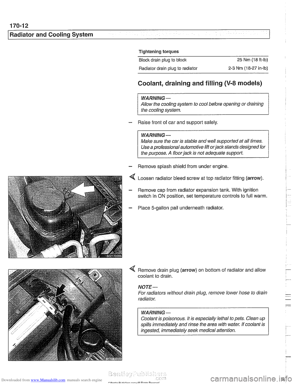
Loosen radiator bleed screw at top radiator fining (arrow).
Remove cap from radiator expansion tank. With ignition
switch in
ON position, set temperature controls to full warm.
Place 5-gallon pail underneath radiator.
4 Remove drain plug (arrow) on bottom of radiator and allow
coolant to drain.
NOTE-
For radiators without drain plug, remove lower hose to drain
radiator.
WARNING
-
Coolant is poisonous. It is especially lethal to pets. Clean up
spills immediately and rinse the area with water. If coolant is
ingested, immediately seek medical attention.