Volume 2 BMW 540i 1998 E39 Workshop Manual
[x] Cancel search | Manufacturer: BMW, Model Year: 1998, Model line: 540i, Model: BMW 540i 1998 E39Pages: 1002
Page 3 of 1002
Downloaded from www.Manualslib.com manuals search engine
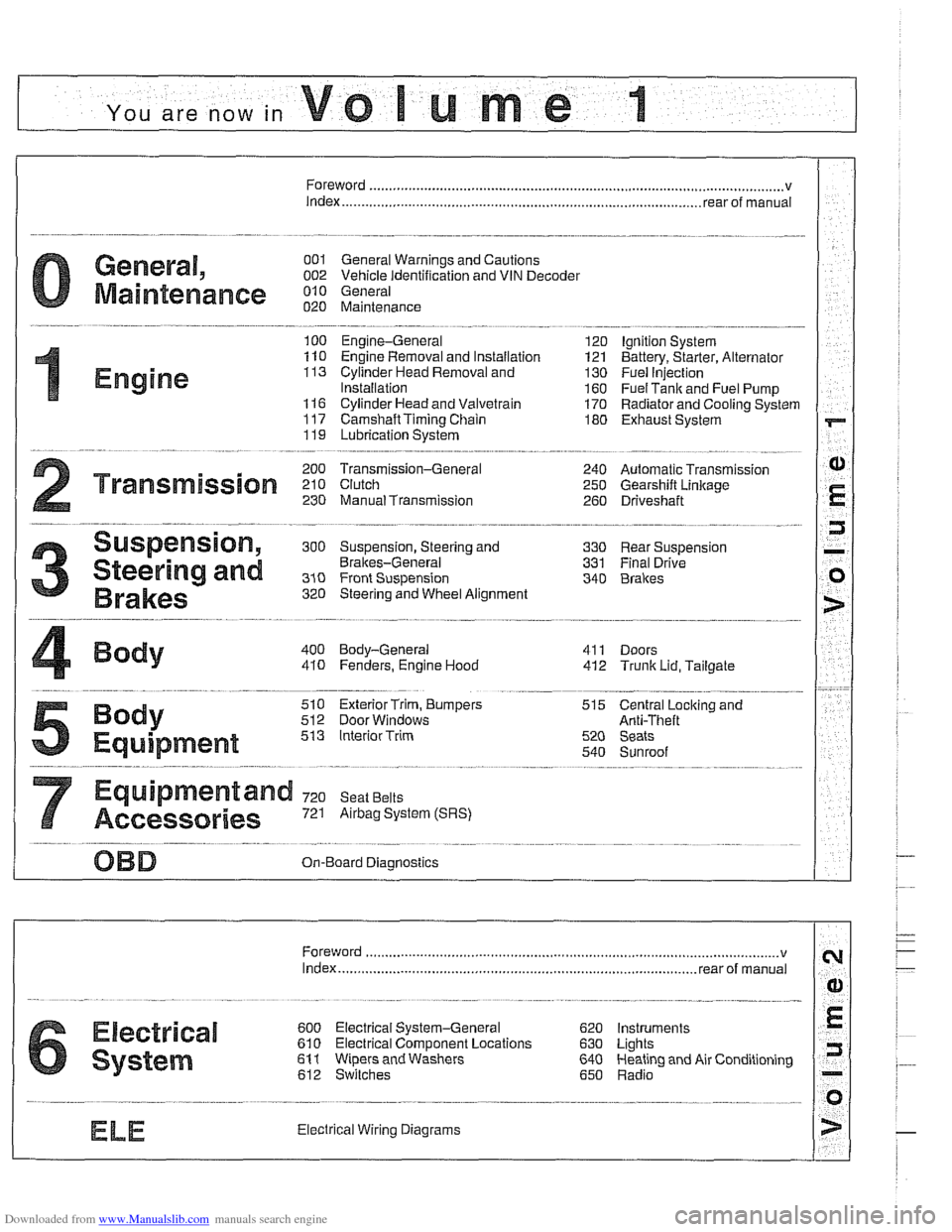
YOU are now in Volume I
I
Foreword ................... .. ........................................................................\
.......... v
Index
........................ .. ................................................................ rear of manual
General, 001 General Warnings and Cautions 002 Vehicle Identification and VIN Decoder
Maintenance OiO 020 Maintenance
Engine
100 Engine-General 110 Engine Removal and Installation
113 Cylinder Head Removal and
Installation
116 Cyiinder Head and Valvetrain 117 Camshaft Timing Chain
119 Lubrication System
200 Transmission-General
2 Transmission 210 clutch 230 ManualTransmission
I20 Ignition System
121 Battery, Starter, Alternator
130 Fuel Injection
160 Fuel Tank and Fuel Pump 170 Radiator and Cooling System
180 Exhaust System
240 Automatic Transmission
250 Gearshift Linkage 260 Driveshaft
Suspension, 300 Suspension, Steering and 330 Rear Suspension
Brakes-General 331 Final Drive
Steering and No Front Suspension 340 Brakes
320 Steering and Wheel Alignment
400 Body-General
410 Fenders, Engine Hood 411 Doors
412 Trunk Lid, Tailgate
510 Exterior Trim, Bumpers 512 Door Windows
Equipment 513 Interior Trim
7
Equipment and 720 seat Belts
Accessories 721 Airbag System (SRS)
OBD On-Board Diagnostics
. ............ ..
515 Central Lociting and
Anti-Theft
520 Seats 540 Sunroof
.................................................................... Foreword .............................. .. v
Index ................... .. ................................................................ rear of manual
Electrical
6 system
600 Electrical System-General 620 Instruments
610 Electrical Comoonent Locations 630 Liohts
611 wipers and washers 612 Switches eati in^ and Air Conditioning
Radio
. ........... ........ .........................
Electrical Wiring Diagrams
Page 35 of 1002
Downloaded from www.Manualslib.com manuals search engine
Maintenance
Service Interval lndicator (Sll)
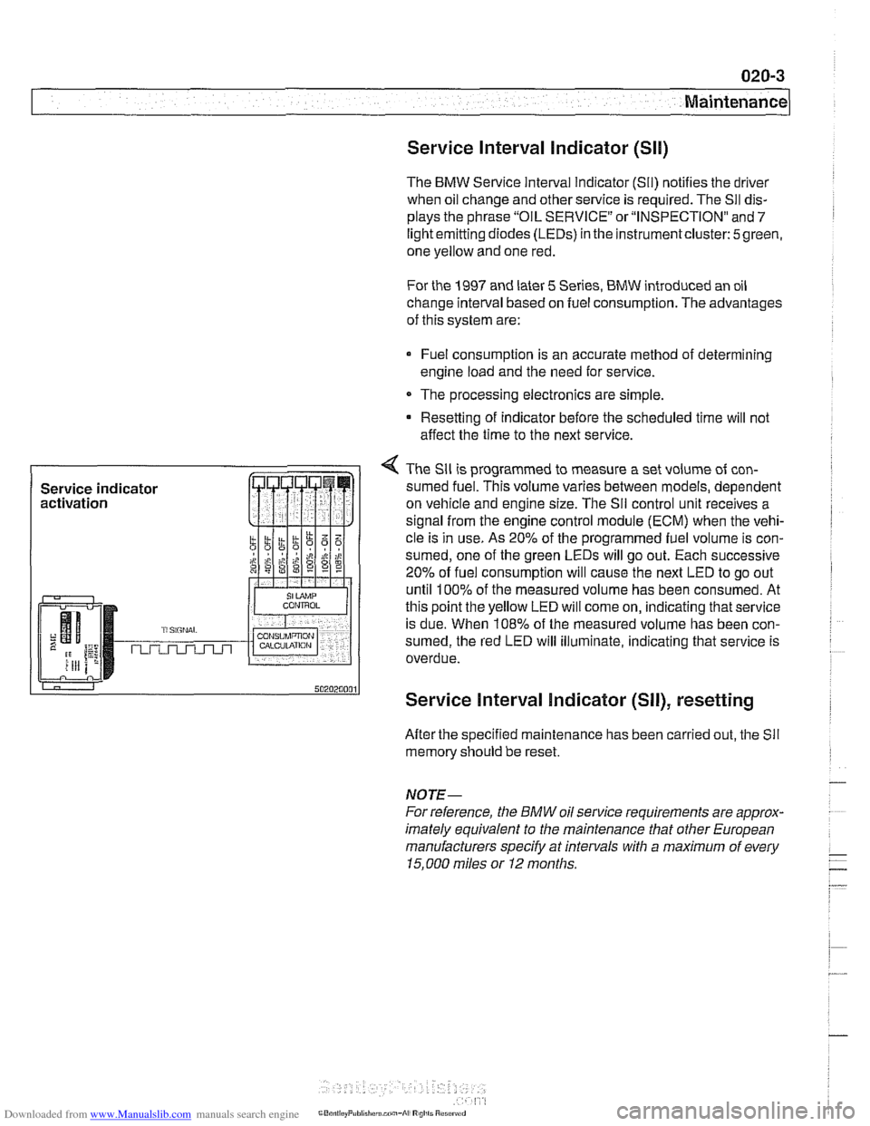
The BMW Service Interval lndicator (SII) notifies the driver
when oil change and other service is required. The
Sll dis-
plays the phrase "OIL SERVICE"
or"INSPECTI0N" and 7
light emitting diodes (LEDs) in the Instrumentcluster: 5green,
one yellow and one red.
For the
1997 and later 5 Series, BMW introduced an oil
change interval based on fuel consumption. The advantages
of this system are:
Fuel consumption is an accurate method of determining
engine load and the need for service.
The processing electronics are simple.
Resetting of indicator before the scheduled time will not
affect the time to the next service.
4 The Sll is programmed to measure a set volume of con-
sumed fuel. This volume varies between models, dependent
on vehicle and engine size. The
Sil control unit receives a
signal from the engine control module (ECM) when the vehi-
cle is in use. As
20% of the programmed fuel volume is con-
sumed, one of the green LEDs will go out. Each successive
20% of fuel consumption will cause the next LED to go out
until
100% of the measured volume has been consumed. At
this point the yellow LED will come on, indicating that service
is due. When
108% of the measured volume has been con-
sumed, the red LED will illuminate, indicating that service is
overdue.
Service Interval Indicator (SII), resetting
After the specified maintenance has been carried out, the Sll
memory should be reset.
NOTE-
For reference, the BMW oil service requirements are approx-
imately equivalent to the maintenance tliat other European
manufacturers specify at intervals with a maximum of every
15.000 miles or I2 months.
Page 42 of 1002
Downloaded from www.Manualslib.com manuals search engine
020-1 0
Maintenance Fluids and lubricants
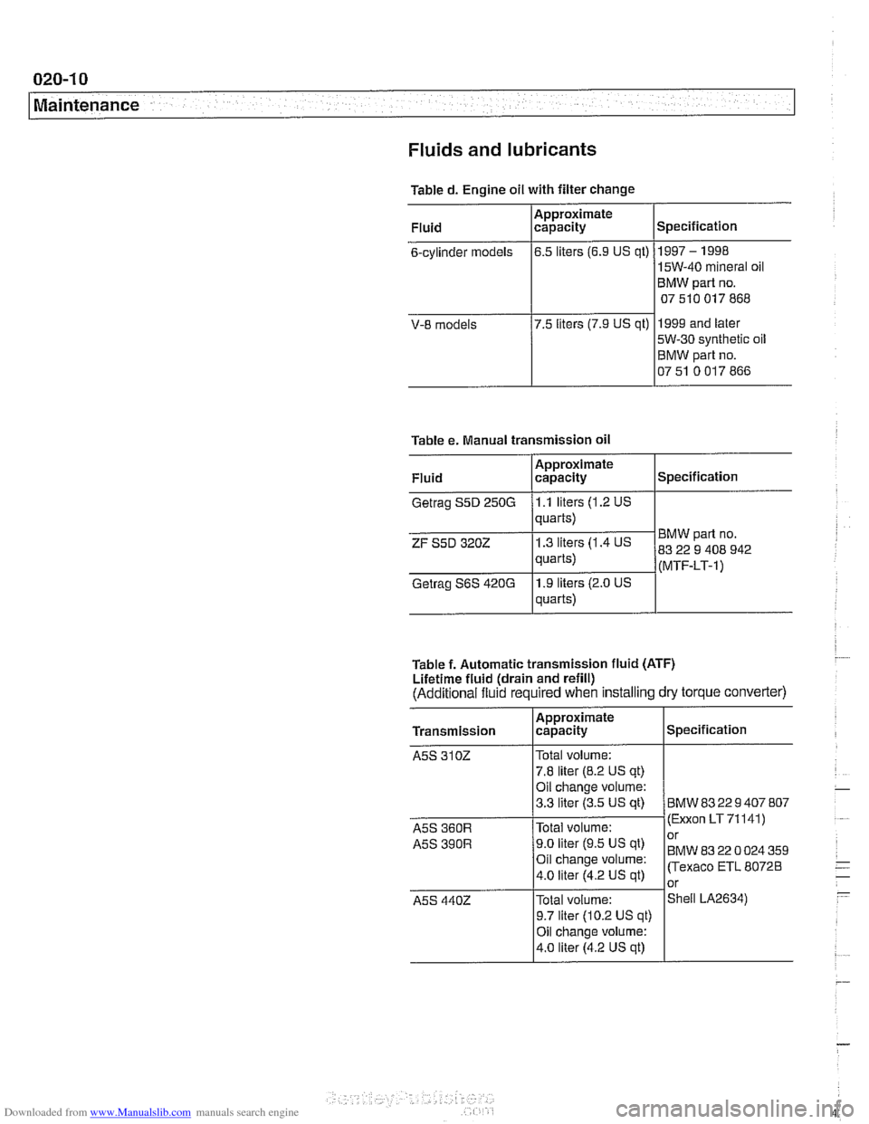
Table d. Engine oil with filter change
V-8
models
BMW part no.
07 510 017 868
5W-30 synthetic oil
BMW part no.
07 51 0 017 866
Specification
1997
- 1998
15W-40 mineral oil
Fluid
6-cylinder models
Table e. Manual transmission oil
Approximate
capacity
6.5
liters (6.9 US qt)
Specification
Fluid
I I
Approximate
capacity
Getrag S5D 250G 1 .I liters (1.2 US
quarts) BMW
part no.
83 22 408 942
I
quarts)
Getrao
S6S 420G 11.9
liters (2.0 US
Table f. Automatic transmission fluid
(ATF)
Lifetime fluid (drain and refill)
(Additional fluid required when installing dry torque converter)
ZF S5D
3202
(MTF-LT-1)
u
Approximate I , , . Transmission Icapacity Spec~flcatlon
1.3 liters (1.4 US . .
quarts)
A5S 31 02
Trell~~2634) Total 9.7 liter volume: (10.2 US qt)
A5S
4402
Oil change volume:
4.0 liter (4.2 US qt)
I
A5S 360R /~otal volume:
Total
volume:
7.8 liter (8.2 US qt)
Oil change volume:
3.3 liter (3.5 US
qt)
(Exxon LT 71141) -.
BMW 83229407 807
Page 396 of 1002
Downloaded from www.Manualslib.com manuals search engine
130-6
Fuel Injection
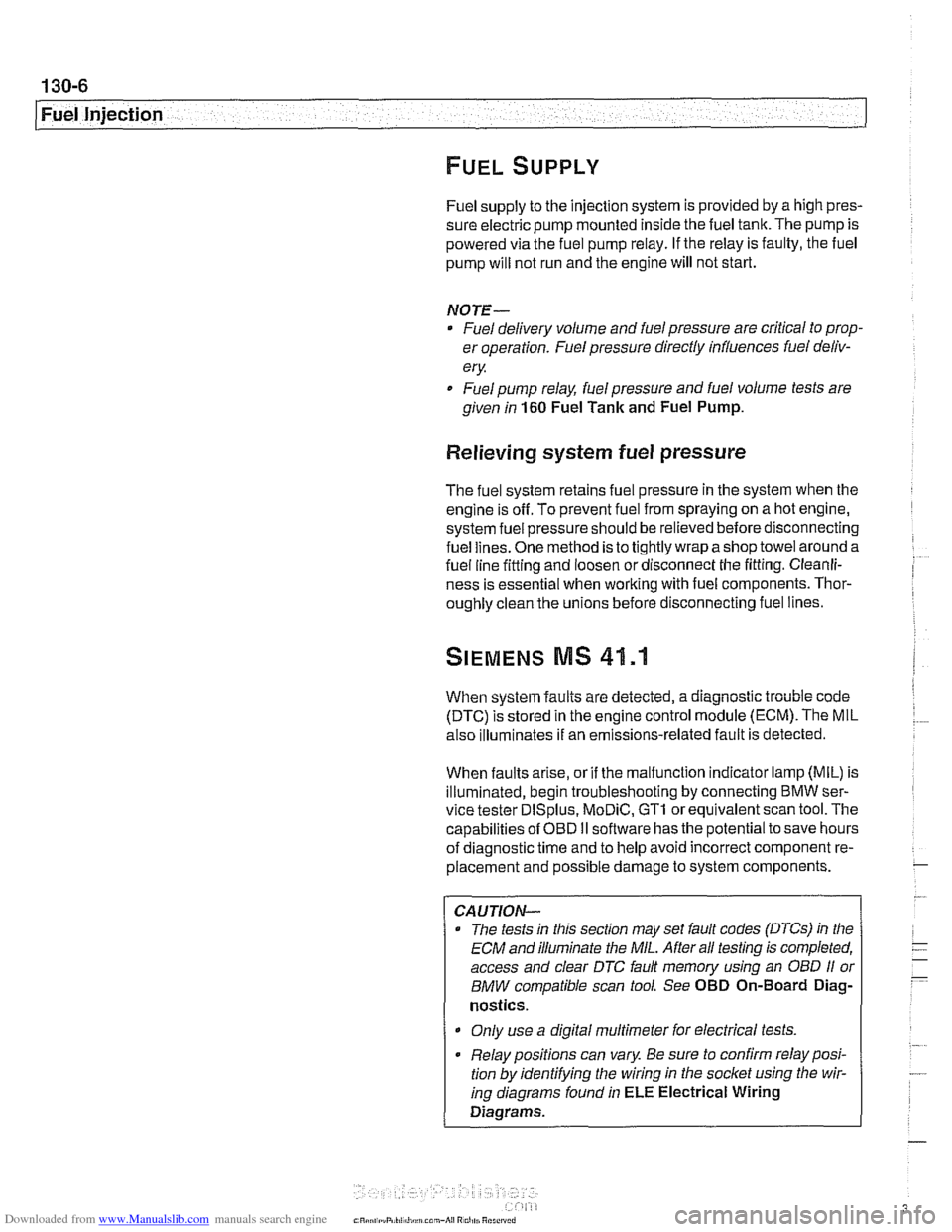
Fuel supply to the injection system is provided by a high pres-
sure electric pump mounted inside the fuel tank. The pump is
powered via the fuel pump relay. If the relay is faulty, the fuel
pump will not run and the engine will not start.
NOTE-
* Fuel delivery volume and fuel pressure are critical to prop-
er operation. Fuel pressure direcfly influences fuel deliv-
ery
Fuel pump relay, fuel pressure and fuel volume tests are
given in 160 Fuel Tank and Fuel Pump.
Relieving system fuel pressure
The fuel system retains fuel pressure in the system when the
engine is off. To prevent fuel from spraying on a hot engine,
system fuel pressure should be relieved beforedisconnecting
fuel lines. One method is to tightly wrap
ashop towel around a
fuel line fitting and loosen or disconnect the fitting. Cleanli-
ness is essential when working with fuel components. Thor-
oughly clean the unions before disconnecting fuel lines.
When system faults are detected, a diagnostic trouble code
(DTC) is stored in the engine control module (ECM). The MIL
also iiluminates if an emissions-related fault is detected
When faults arise, or if the malfunction indicator lamp (MIL) is
illuminated, begin troubleshooting by connecting BMW ser-
vice tester
DISplus. MoDiC, GTI or equivalent scan tool. The
capabilities of OBD
II software has the potential to save hours
of diagnostic time and to help avoid incorrect component re-
placement and possible damage to system components.
CAUTION-
- The tests in this section may set fault codes (DTCs) in the
ECM and illuminate the
MIL. Affer all testing is completed,
access and clear DJC fault memory using an
OED I1 or
BMW compatible scan tool. See OBD On-Board Diag-
nostics.
0 Only use a digital multimeter for electrical tests.
. Relay positions can vary Be sure to confirm relay posi-
tion by identifying the wiring in the socket using the wir-
ing diagrams found in ELE Electrical Wiring
Diagrams.
Page 473 of 1002
Downloaded from www.Manualslib.com manuals search engine
Fuel Tank and Fuel Pump
Fuel pump
The electric fuel pump is mounted in the fuel tank in tandem
with the right side fuel level sender. The fuel pump delivers
pressurized fuel to the fuel injection system.
A pressure regu-
lator maintains system pressure. The quantity of fuel supplied
exceeds demand, so excess fuel returns to the fuel tank via a
return line. See
130 Fuel Injection for more information.
NOTE-
Fuel pump removal procedures are given under Fuel level
sender (right side) and fuel pump, removing and install-
ing.
Fuel tank evaporative control system
Evaporative control, also referred to as running losses con-
trol, is designed to prevent fuel system evaporative losses
from venting into the atmosphere.
The components of this system allow control and monitoring
of evaporative losses by the on-board diagnostic
(OED II)
software incorporated into the engine control module (ECM).
NOTE-
1997 V-8 models (540i) with Bosch DME M5.2 are not
equipped with an
OBD I1 running losses monitoring system.
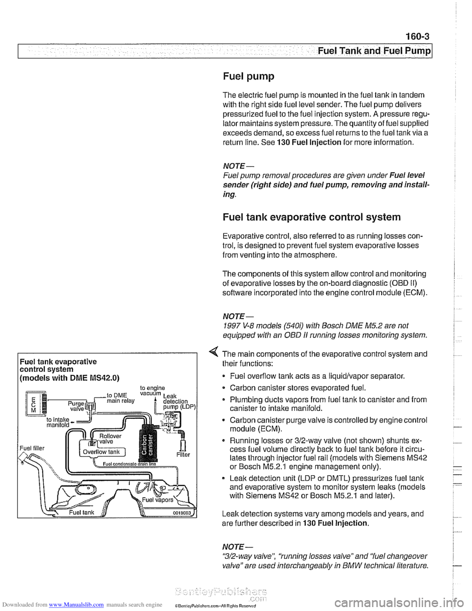
Fuel tank evaporative
control system
(models with
DME MS42.0)
4 The main components of the evaporative control system and
their functions:
Fuel overflow
tank acts as a liquidlvapor separator
Carbon canister stores evaporated fuel.
Plumbing ducts vapors from fuel tank to canister and from
canister to intake
manifold.
- Carbon canister purge valve is controlled by enginecontrol
module (ECM).
Running losses or 312-way valve (not shown) shunts ex-
cess fuel volume directly
back to fuel tank before it circu-
lates through injector fuel rail (models with Siemens MS42
or Bosch M5.2.1 engine management only).
Leak detection unit (LDP or DMTL) pressurizes fuel
tank
and evaporative system to monitor system leaks (models
with Siemens MS42 or Bosch M5.2.1 and later).
Leak detection systems vary among models and years, and
are further described in
130 Fuel Injection.
NOTE -
"3/2-way valve", 'tunning losses valve" and "fuel changeover
valve" are used interchangeably
in BMW technical literature.
Page 482 of 1002
Downloaded from www.Manualslib.com manuals search engine
Fuel Tank and Fuel Pump
Fuel delivery,
testing
Checitino fuel delive~ is a fundamental oart of troubleshoot- .. ing and diagnosing thk DME system. ~ukl pressure directly
influences
fuel delivery. An accurate fuel pressure gauge will
be needed to make the tests.
There are two significant fuel deliveryvalues to be measured:
* System pressure - created by fuel pump and maintained
by pressure regulator
Residual pressure
- pressure maintained in closed sys-
tem after engine and fuel pump are shut off
if proper system pressure and residual pressure are present,
also check for problems in fuel delivery volume, which can be
affected by restrictions such as clogged fuel filter or fuel pick-
up port in the fuel tank.
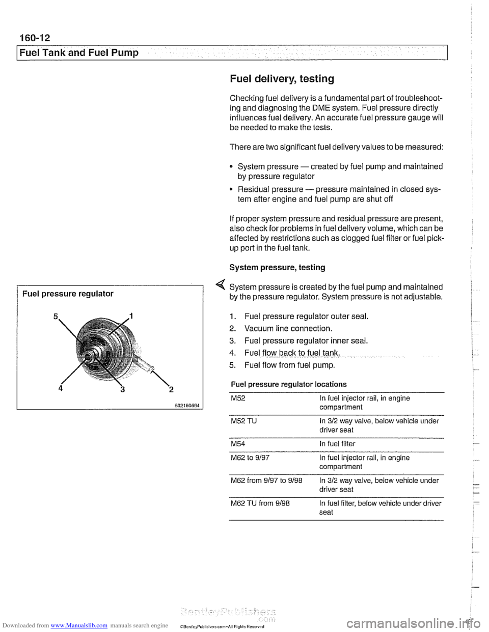
System pressure, testing
1. Fuel pressure regulator outer seal
4 System pressure is created by the fuel pump and maintained
2. Vacuum line connection.
3. Fuel pressure regulator Inner seal.
4. Fuel flow back to fuel tank.
5. Fuel flow from fuel pump.
Fuel pressure
regulator
Fuel pressure regulator locations
M52 In fuel injector rail, in engine
compartment
M52 TU In 312 way valve, below vehicle under
driver seat
by the pressure
regulator. System pressure is not adjustable.
M54 In fuel filter
M62 to 9/97 In fuel injector rail, in engine
compartment
M62 from 9/97 to 9/98 In 312 way valve, below vehicle under
driver seat
M62 TU from 9/98 In fuel filter, below vehicle under driver
seat
Page 494 of 1002
Downloaded from www.Manualslib.com manuals search engine
Fuel Tank and Fuel Pump 1
Activated carbon canister I fuel tank leak
detection unit
(LDP or DMTL), removing . . -
and installing
- Raise rear end of car and support safely.
CAUTION-
Make sure the car is stable and well supported at all times.
Use a professional automotive lift
orjack stands designed for
the purpose.
A floor jack is not adequate support.
- Remove left rear wheel and inner fender panel
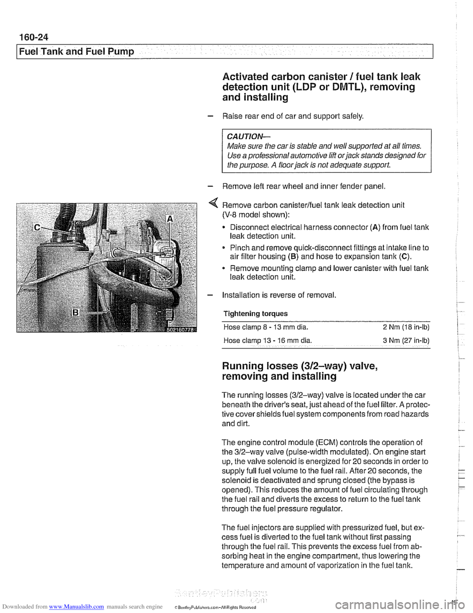
Remove carbon canisterlfuel tank leak detection unit
(V-8 model shown):
Disconnect electrical harness connector
(A) from fuel tank
leak detection unit.
Pinch and remove quick-disconnect fittings at intake line to
air filter housing
(5) and hose to expansion tank (C).
* Remove mounting clamp and lower canister with fuel tank
leak detection unit.
Installation is reverse of removal.
Tightening
torques
Hose clamp 8 - 13 mm dia. 2 Nrn (18 in-lb)
Hose clamp
13 - 16 rnm dia 3 Nm (27 in-lb)
Running losses (312-way) valve,
removing and installing
The running losses (312-way) valve is located under the car
beneath the driver's seat, just ahead of the fuel filter. A protec-
tive covershieldsfuel system components from road hazards
and dirt.
The engine control module
(ECM) controls the operation of
the 312-way valve (pulse-width modulated). On engine start
up, the valve solenoid is energized for 20 seconds in order to
supply full fuel volume to the fuel rail.
After20 seconds, the
solenoid is deactivated and sprung closed (the bypass is
opened). This reduces the amount of fuel circulating through
the fuel rail and diverts the excess to return to the fuel tank
through the fuel pressure regulator.
The fuel injectors are supplied with pressurized fuel, but ex-
cess fuel is diverted to the fuel tank without first passing
through the fuel rail. This prevents the excess fuel from ab-
sorbing heat in the engine compartment, thus lowering the
temperature and amount of vaporization in the fuel tank.
Page 885 of 1002
Downloaded from www.Manualslib.com manuals search engine
Interior Trim
The E39 dashboard assembly includes the instrument clus-
ter, passenger side
airbag, glove compartment, fuse and re-
lay panel, radio. IHKA control panel oron-board monitor (if
equipped with GPS). The dash is made up of an upper and
lower sections. The lower section must be remove before the
upper section can be removed.
Dashboard removal is a complex operation. Read the proce-
dures through before starting work.
Lower dash panel assembly, removing and
installing
- Disconnect negative (-) cable from battery and cover termi-
nal with
insulating material.
--7
CAUTION-
Prior to disconnecting the battery, read the battery discon-
nectioncautionsgiven atthe irontin001 General Warnings
and Cautions.
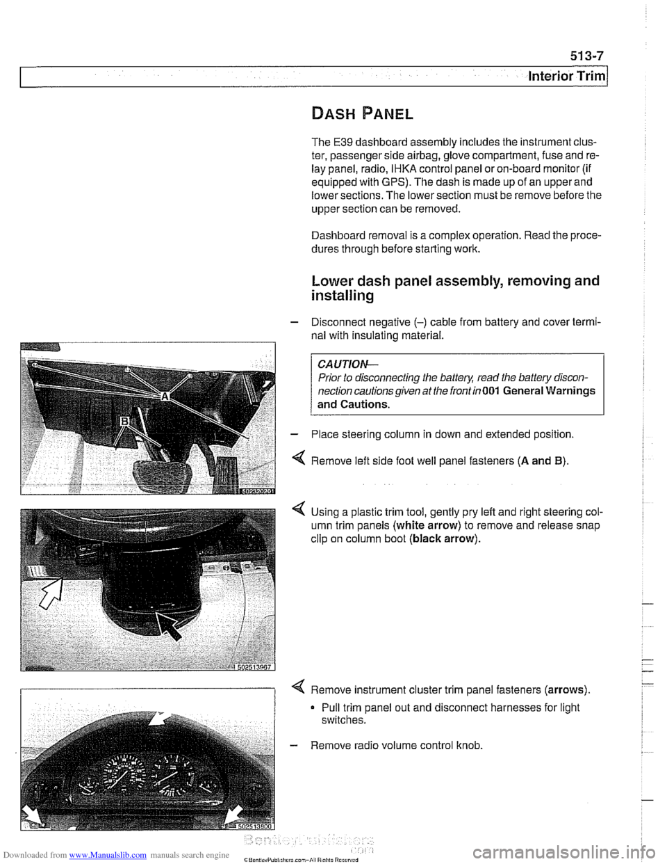
- Place steering column in down and extended position.
4 Remove left side foot well panel fasteners (A and B).
< Using a plastic trim tool, gently pry left and right steering col-
umn trim panels (white arrow) to remove and release snap
clip on column boot
(black arrow).
I 1 < Remove instrument cluster trim panel fasteners (arrows).
Pull trim panel out and disconnect harnesses for light
switches.
- Remove radio volume control knob.
Page 973 of 1002
Downloaded from www.Manualslib.com manuals search engine
On-Board Diagnostics
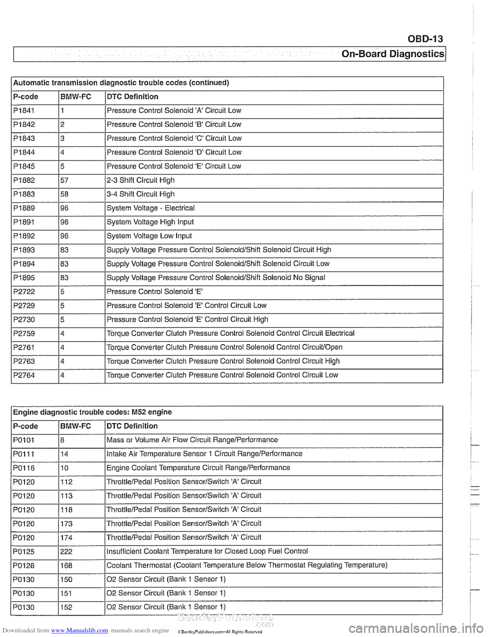
l~utomatic transmission diagnostic trouble codes (continued)
P-code
1 Pi844
I I
14 /Pressure Control Solenoid 'D' Circuit Low
I I PI841 11 /Pressure Control Solenoid 'A' Circuit Low
BMW-FC
Pi842
I
P2722 15 I Pressure Control Solenoid 'E' I
DTC
Definition
Pi 845
Pi 882
Pi 883
PI 889
PI891
PI 892
PI 893
Pi 843 3 8
2 Pressure Control Solenoid '0' Circuit Low
5
57
58
96
96
96
83
P2729
P2730
P2759
P2761
P2763
P2764
Pressure Control Solenoid 'E' Circuit Low
2-3 Shift Circuit High
3-4 Shift Circuit High
System Voltage
- Electrical
System Voltage High Input
System Voltage Low Input
SUDP~V Voltaqe Pressure Control SoienoidIShift Solenoid Circuit High
~~ ~~ ~ Engine diagnostic trouble codes: M52 engine
5
5
4
4
4
4
I I
Pressure Control Solenoid 'E' Control Circuit Low
Pressure Control Solenoid
'E' Control Circuit High
Torque Converter Clutch Pressure Control
Solenoid Control Circuit Electrical
Torque Converter Clutch Pressure Control Solenoid Control
Circuitlopen
Torque Converter Clutch Pressure Control Solenoid Control Circuit High
Torque Converter Clutch Pressure Control Solenoid Control Circuit Low
DTC Definition
Mass or Volume Air
Flow Circuit RangeIPerformance
lntalte Air Temperature Sensor 1 Circuit Rangelperformance
Engine Coolant Temperature Circuit RangeIPerformance
ThrottieIPedai Position SensorISwitch 'A' Circuit
ThrottleIPedai Position SensorISwitch 'A' Circuit
P-code
PO1
01
PO1 11
PO116
PO120
PO120
PO1 20 BMW-FC
8 14
10
112
113
POI 20 1173 /~hrottie/~edal Position SensorISwitch 'A' Circuit
118
ThrottieIPedai Position SensorISwitch 'A' Circuit
Page 975 of 1002
Downloaded from www.Manualslib.com manuals search engine
OBD-15
On-Board ~iagnosticsl
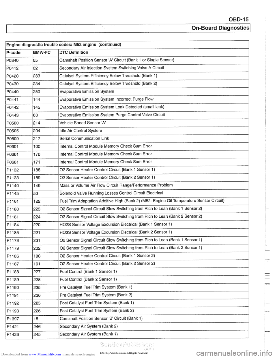
Engine diagnostic trouble codes: M52 engine (continued)
P-code
PO340
PO412
PO420
PO430
PO440
PO441
PO442
PO443
PO500
PO505
PO600
PO601
PO601
I PO601
~1132
~1133
BMW-FC
65
62
233
234
250 144
-
145
68
214
i I
DTC Definition
Camshalt Position Sensor 'A' Circuit (Bank 1 or Single Sensor)
Secondary Air Injection System Switching Valve A Circuit
Catalyst System Efficiency Below Threshold
(Bank 1)
Catalyst System Efficiency Below Threshold (Bank 2)
Evaporative Emission System
Eva~orative Emission Svstem Incorrect Purge Flow .
Evaporative Emission System Leak Detected (small leak)
Evaporative Emission System Purge Control Valve Circuit
Vehicle Speed Sensor 'A'
204
21 7
100
170
171
188
189
PI161
PI180
PI181
PI184
PI185
PI178
02 Sensor Heater Control Circuit (Bank 2 Sensor 2) I
idle Air Control System
Serial Communication
Link
Internal Control Module Memory Check Sum Error
Internal Control Module Memory
Check Sum Error
Internal Control Module Memory
Check Sum Error
02 Sensor Heater Control Circuit (Bank 1 Sensor
1)
02 Sensor Heater Control Circuit (Bank 2 Sensor 1)
Mass or Volume Air Flow Circuit RangeIPerlormance Problem PI140
I
I I
P1188 1227 I Fuel Control (Bank 1 Sensor 1)
PI145 150 /Solenoid Valve Running Losses Control Circuit Electrical
149
122
223
224
220 221
231
I I
P1189 1228 I Fuel Control (Banlc 2 Sensor 1)
Fuel Trim Adaptation Additive High (Bank 2) (M52: Engine Oil Temperature Sensor Circuit)
02 Sensor Signal Circuit Slow Switching from Rich to Lean
(Bank 1 Sensor 2)
02 Sensor Signal Circuit Slow Switching from Rich to Lean
(Bank 2 Sensor 2)
H02S Sensor Voltage Excursion Electrical (Banlc 1 Sensor 1)
HO2S Sensor Voltage Excursion Electrical (Banlc 2 Sensor 1)
02 Sensor Sianai Circuit Slow Switchina from Rich to Lean (Bank 1 Sensor 1)
02 Sensor Signal Circuit Slow Switching from Rich to Lean (Bank 2 Sensor 1) PI179
I I
PI190 1235 I Pre Catalyst Fuel Trim System (Banlc 1)
PI186 1190 102 Sensor Heater Control Circuit (Banlc 1 Sensor 2)
232
I I
PI191 1236 I Pre
Catalyst Fuel Trim System (Banlc 2)
PI192
. . -- - i Pi193 1226 I Post Catalvst Fuel Trim Svstem (Bank 2)
225
PI397
I I
Post Catalyst Fuel Trim System (Bank 1)
PI421 1246 /Secondarv Air System (Bank 2)
18
Secondary Air System (Bank
1) PI423
Camshaft Position Sensor '0' Circuit (Bank 1)
I 245