page 60 BMW 540i 1998 E39 Workshop Manual
[x] Cancel search | Manufacturer: BMW, Model Year: 1998, Model line: 540i, Model: BMW 540i 1998 E39Pages: 1002
Page 5 of 1002
Downloaded from www.Manualslib.com manuals search engine
Foreword
For the BMW owner with basic mechanical skills and for independent auto service professionals.
this manual includes many of the specifications and procedures that were available to an
authorized BMW dealer service deoartment as this manual went to
Dress. The BMW owner with , no intention of working on his or her car will find that owning and referring to this manual makes it
possible to be better informed and to more
Itnowledgeably discuss repairs with a professional
automotive technician.
If you are a BMW owner intending to do maintenance and repair work, make sure you have
screwdrivers, a set of metric wrenches and sockets and metric Allen and
Torx wrenches, since
these basic hand tools are needed for most of the work described in
this manual. Many procedures
also require a torque wrench to ensure that fasteners are tightened properly and in accordance
with specifications. Additional information on basic tools and other tips are in
010 General. In
some cases, the text refers to special tools that are recommended or required to accomplish
adjustments or repairs. These tools are usually identified by their
BMW special tool number and
illustrated.
Disclaimer
We have endeavored to ensure the accuracy of the information in this manual. When the vast
array of data presented in the manual is
talten into account, however, no claim to infallibility can
be made. We therefore cannot be responsible for the result of any errors that may have crept into
the text. Please also read the Important Safety Notice on the copyright page at the beginning of
this book.
Prior to starting a repair procedure, read the procedure,
001 General Warnings and Cautions
and the warnigns and cautions that accompany the procedure. Reading a procedure before
beginning
work will help you determine in advance the need for specific skills, identify hazards,
prepare for appropriate capture and handling of hazardous materials, and the need for particular
tools and replacement parts such as gasltets.
Bentley Publishers encourages comments from the readers of this manual with regard to errors,
and/or suggestions for improvement of our product. These communications have been and will be
carefully considered in the preparation of this and other manuals. If you identify inconsistencies in
the manual, you may have found an error. Please contact the publisher and we will endeavor to
post applicable corrections on our
website. Posted corrections (errata) should be reviewed before
beginning
worlc. Please see the following web address:
BMW offers extensive warranties, especially on components of the fuel delivery and emission
control systems. Therefore, before deciding to repair a BMW that may be covered wholly or in part
by any warranties issued by
BMW of North America, LLC, consult your authorized BMW dealer.
You may find that the dealer can
make the repair either free or at minimum cost. Regardless of its
age, or whether it is under warranty, your BMW
Is both an easy car to service and an easy car to
get serviced. So
if at any time a repair is needed that you feel is too difficult to do yourself, a trained
BMW technician is ready to do the job for you.
Bentley Publishers
Page 7 of 1002
Downloaded from www.Manualslib.com manuals search engine
001 General Warnings and Cautions
PLEASE READ THESE WARNINGS AND CAUTIONS
BEFORE PROCEEDING
WITH MAINTENANCE AND REPAIR WORK.
WARNINGS-
See also CAUTIONS
- Some repairs may be beyond your capability. If you lack the skills, - Catch draining fuel, oil, or brake fluid in suitable containers. Do
tools and equipment, or a suitable workplace for any procedure
not use
foodor beverage containers that might mislead someone
described in this manual, we suggest you leave such repairs to
into
drinking from them. Store flammable fluids away from fire
an authorized BMW dealer service department or other qualified
hazards. Wipe up spills at once, but do not store the oily rags,
shop. which can ignite and burn spontaneously.
. Do not reuse any fasteners that are worn or deformed. Many fas- Always observe good worRshop practices. Wear qoqqles when
teners are designed to be used only once and become
unreliable you operate machine tools or work with battery acid:kloves or
and mav fail when used a second time. This includes, but is not other
~rotective clothino should be worn whenever the iob re-
limited io, nuts, bolts, washers, self-locking nuts or bolts, clrclips yires' working with harmful substances.
and cotter pins. Always replace these fasteners with new parts.
Greases, lubricants and other automotive chemicals contain toxic
. Never work under a lifted car unless it is solidly supported on
substances, many of which are absorbed directly through the
stands
desiqned for the purpose. Do not supeort a car on cinder
skin. Read the manufacturer's instructions and warninos careful-
blochs, hollow tiles orotherbrops that may drurnbie undercontin-
uous toad. Never work under a car that is supported solely by a
iack. Never work under the car
while the enqine is runninq. - -
If you aregoing to work underacaron the ground, makesure that
the ground is level. Block the wheels to
keep the car from rolling.
Disconnect the battery negative
(-) terminal to prevent others
from starting the car while you are under it.
- Never run the engine unless the work area is well ventilated. Car-
bon monoxide kills.
Rings, bracelets and other jewelry should be removed so that
they cannot cause electrical shorts, get caught in running ma-
chinery, or be crushed by heavy parts.
- Tie long hair behind your head. Do not wear a necktie, a scarf.
loose clothing, or a necklace when you work near machine tools
or running engines. if your hair, clothing, or jewelry were to get
caught in the machinery, severe injury could result.
DO not attempt to
work on your car if you do not feel well. You in-
crease the
danger of injuryto yourseliand others if you are tired,
uDset or have taken medication or anv other substance that mav
keep you from being fully alert.
Illuminate your work area adequately but safely. Use a portable
iy. Use hand and eye protection. Avoid direct skin conGct.
Disconnect the battery negative (-) terminal whenever you work
on the fuel system
orthe electrical system. Do not smokeorwork
near heaters or other fire hazards. Keep an approved fire extin-
guisher handy.
. Friction materials (such as brake pads or shoes or clutch discs)
contain asbestos fibers or other friction materials. Do not create
dust by grinding, sanding, or by cleaning with compressed air.
Avoid breathing dust. Breathing any
friclion material dust can
lead to serious diseases and may result in death.
Batteries
giveoff explosive hydrogen gas during charging. Keep
sparks, lighted matches and open flame away from the top of the
battery. If hydrogen gas escaping from the cap vents is ignited, it
will ignite gas trapped in the cells and cause the battery to ex-
plode.
Connect and disconnect battery cables, jumper cables or a bat-
tery charger only wilh the ignition switched off. Do not disconnect
the battery while the engine is running.
Do not quick-charge the battery (for boost starting) for longer
than one minute. Wait at least one minute before boosting the
battery a second time.
. . safety lighiforworking lnsideor under the car. Make sure the bulb - Do not allow battery charging vollage to exceed 16.5 volts. If the
is enclosed bv a wire caoe. The hot filament of an accidentallv
batten! beoins ~roducina oas or boilino violentiv, reduce the
broken bulb can ignite spilled
fuel, vapors or oil. , - - - charglng rate. ~oostlng a sutfaled battery at a igh charging rate
can cause an
explosion.
-
Continued on next page
Page 47 of 1002
Downloaded from www.Manualslib.com manuals search engine
Maintenance
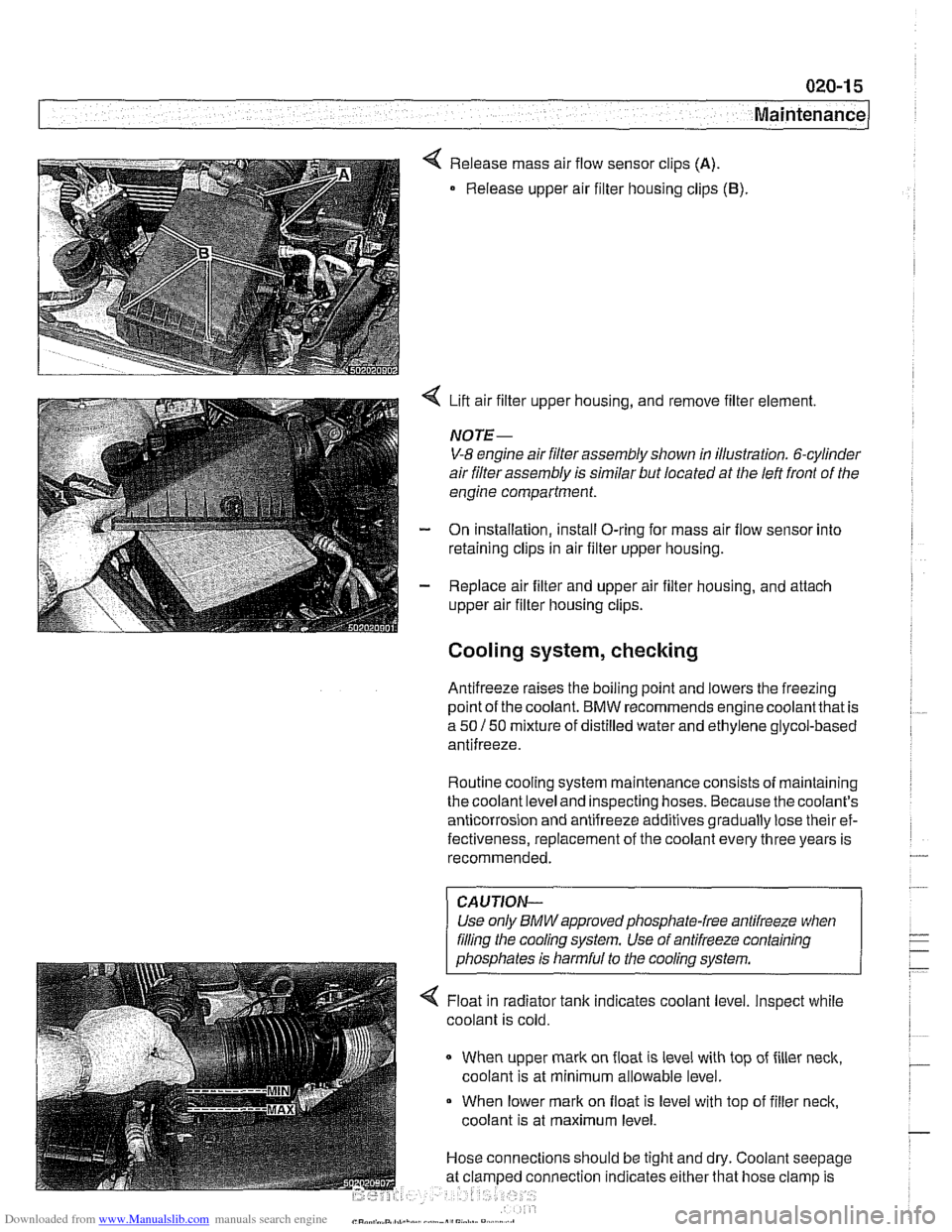
< Release mass air flow sensor clips (A).
Release upper air filter housing clips (B).
4 Lift air filter upper housing, and remove filter element.
NOTE-
V-8 engine air filter assembly shown in illustration. 6-cylinder
air filter assembly is similar but located at the left front of the
engine compartment.
- On installation, install O-ring for mass air flow sensor into
retaining clips in air filter upper housing.
- Replace air filter and upper air filter housing, and attach
upper air filter housing clips.
Cooling system, checking
Antifreeze raises the boiling point and lowers the freezing
~oint of the coolant. BMW recommends enaine coolantthat is
a 50 150 mixture of distilled water and ethGene glycol-based
antifreeze.
Routine cooling system maintenance consists of maintaining
the coolant level and inspecting hoses. Because the coolant's
anticorrosion and antifreeze additives gradually lose their ef-
fectiveness, replacement of the coolant every three years is
recommended.
CAUJION-
Use only BMWapprovedphosphate-free antifreeze when
filing the cooling system. Use of antifreeze containing
phosphates is harmful to the cooling system.
4 Float in radiator tank indicates coolant level. Inspect while
coolant is cold.
When upper mark on float is level with top of filler neck,
coolant is at minimum allowable level.
When lower mark on float is level with top of filler neck,
coolant is at maximum level.
Hose connections should be tight and dry. Coolant seepage
nnection indicates either that hose clamp is
Page 111 of 1002
Downloaded from www.Manualslib.com manuals search engine
Cylinder Head Removal -- and lnstallati~i
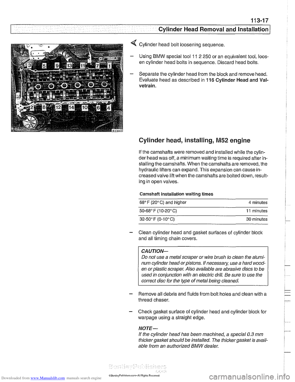
4 Cylinder head bolt loosening sequence.
- Using BMW special tool 11 2 250 or an equivalent tool, loos-
en cylinder head bolts in sequence. Discard head bolts.
- Separate the cylinder head from the block and remove head.
Evaluate head as described in
116 Cylinder Head and Val-
vetrain.
Cylinder head, installing, M52 engine
If the camshafts were removed and installed while the cylin-
der head was off, a minimum waiting time is required after in-
stalling the camshafts. When the camshafts are removed, the
hydraulic lifters can expand. This expansion can cause in-
creased valve lift when the camshafts are bolted down, result-
ing in open valves.
Camshaft installation waiting times
68" F (20" C) and higher 4 minutes
50.68' F (1 0-20" C) 11 minutes
32-50' F (0-1 0" C) 30 minutes
- Clean cylinder head and gasket surfaces of cylinder block
and all timing chain covers.
CAUTION-
Do not use a metal scraper or wire brush to clean the alumi-
num cylinder head orpistons. If necessary, use a hard wood-
en orplastic scraper. Also available are abrasive discs to be
used in conjunction with an electric drill. Be sure to use the
correct disc for the type of metal being cleaned.
- Remove all debris and fluids from bolt holes and clean with a
thread chaser.
- Check gasket surface of cylinder head and cylinder block for
warpage using a straight edge.
NOTE-
If the cylinder head has been machined, a special 0.3 mm
thicker gasket should be installed. The thicker
gasket is avail-
able from an authorized
BMW dealer.
Page 181 of 1002
Downloaded from www.Manualslib.com manuals search engine
11 6-5
I Cylinder Head and valvetrain1
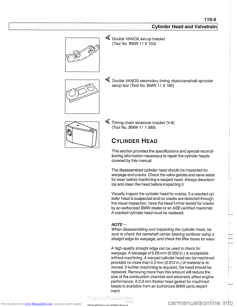
4 Timing chain tensioner bracket (V-8)
(Tool No. BMW
11 7 380)
CYLINDER HEAD
This section provides the specifications and special recondi-
tioning information necessary to repair the cylinder heads
covered by this manual.
The disassembled cylinder head should be inspected for
warpage and cracks. Check the valve guides and valve seats
for wear before machining a warped head. Always decarbon-
ize and clean the head before inspecting it.
Visually inspect the cylinder head for craclts.
If a cracked cyl-
inder head is suspected and no
craclts are detected through
the visual Inspection, have the head further tested for cracks
by an authorized BMW dealer or an ASE certified machinist.
A cracked cylinder head must be replaced.
NOJE-
When disassembling and inspecting the cylinder head, be
sure to
checlc the camshaft carrier bearing surfaces using a
straight edge for
warpage, and check the lifter bores for wear.
A high-quality straight edge can be used to
checlc for
warpage. A warpage of 0.05 mm (0.002 in.) is acceptable
without machining. A warped cylinder head can be machined
provided no more than 0.3
mm (0.012 in.) of material is re-
moved.
If further machining is required, the head should be
replaced. Removing more than this amount will reduce the
size of the combustion chamber and adversely affect engine
performance. A 0.3 mm
thicker head gasket for machined
heads is available from an authorized BMW parts depart-
ment.
Page 182 of 1002
Downloaded from www.Manualslib.com manuals search engine
11 6-6
Cylinder Head and Valvetrain
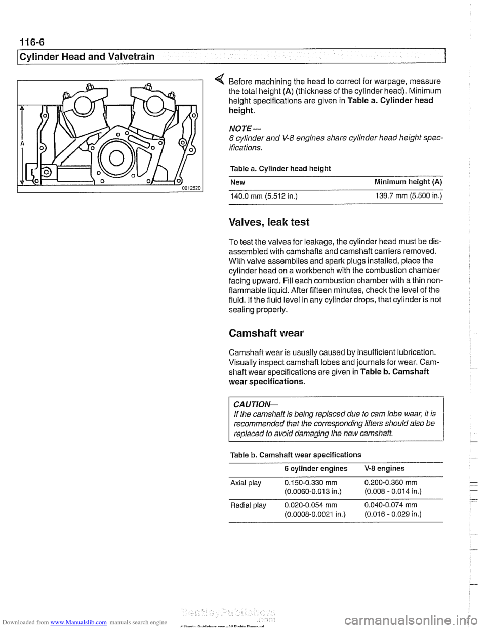
4 Before machining the head to correct for warpage, measure
the total height
(A) (thickness of the cylinder head). Minimum
height specifications are given in Table a. Cylinder head
height.
NOTE-
6 cylinder and V-8 engines share cylinder head height spec-
ifications.
Table a. Cylinder head height
New Minimum height
(A)
140.0 rnrn (5.512 in.) 139.7 rnrn (5.500 in.)
Valves, leak test
To test the valves for leakage, the cylinder head must be dis-
assembled with camshafts and camshaft carriers removed.
With valve assemblies and spark plugs installed, place the
cylinder head on a workbench with the combustion chamber
facing upward. Fill each combustion chamber with a thin non-
flammable liquid. After fifteen minutes, check the level of the
fluid. If the fluid level in any cylinder drops, that cylinder is not
sealing properly.
Camshaft wear
Camshaft wear is usually caused by insufficient lubrication.
Visually inspect camshaft lobes and journals for wear. Cam-
. ~~ shaft wear specifications are given in Table b. Camshaft
wear specifications.
CA UTIOI\C
If the camshaft is being replaced due to cam lobe wear, it is
recommended that the corresponding lifters should also be
replaced to avoid damaging the new camshaft
Table b. Camshaft wear specifications
6 cylinder engines V-8 engines
Axlal play 0.150-0.330 rnrn 0 200-0 360 rnrn - .-
(0.0060-0 013 in.) (0.008 - 0.014 in ) - - Radlal play 0.020-0.054 rnrn 0.040-0.074 rnrn
(0.0008-0.0021 in.) (0.016 - 0.029 in.)
Page 395 of 1002
Downloaded from www.Manualslib.com manuals search engine
Fuel Injection
Warnings and cautions
For personal safety, as well as the protection of sensitive
electronic components, adhere to the warnings and cautions
on the following pages.
WARNING-
Gasoline is highly flammable and its vapors are explosive.
Do not smoke or work on a car near heaters or other fire
hazards when diagnosing and repairing fuel system prob-
lems. Have a fire extinguisher available in case of an emer-
gency
Renew fuel system hoses, clamps and O-rings any
time they are removed.
When working on an open fuel system, wear suitable
hand protection, as prolonged contact
with fuel can
cause illnesses and skin disorders.
* The ignition system produces high voltages that can be
fatal. Avoid contact with exposed terminals. Use ex-
treme caution when
working on a car with the ignition
switched on or the engine running.
CAUTION-
- Disconnecting the battery may erase fault code($ storedin
memory Check for fault codes prior to disconnecting the
battery cables. Read the battery disconnection cautions in
001 General Warnings and Cautions.
a Connect and disconnect the DME system wiring and
1 test equipment leads only when the ignition is switched
off.
Wait at least 1 minute after turning off the ignition be-
fore removing the engine control module (ECM) con-
nector. If the connector is removed before this time,
residualpower in the system relay may damage the
control module.
Fuel system cleaners and other chemical additives oth-
er than those specifically recommended by BMW may
damage the catalytic converter, the oxygen sensor or
other fuel supply components.
* Do not connect any test equipment that delivers a 12-
volt power supply to terminal 15 (+) of the ignition coil.
The current flow may damage the ECM. In general,
connect test equipment only as specified by BMW or
the equipment maker.
Only use a digital
multirneter for electrical tests. Only
use an LED test light for
quiclc tests.
Page 991 of 1002
Downloaded from www.Manualslib.com manuals search engine
INDEX 'tl
WARNING
Your common sense, good
judgemenl, and general alertness are
crucial to sale and successiul service
worlr. Belore attempting any work on
your
BMM be sure lo read 001
General Warnings and Cautions
and the
copyriglll page at the front 01
the manual. Review these warnings
and
caulions each lime you prepare
lo work on your BMW. Please also
read any warnings and cautions that
accompany
tile procedures in the
manual.
312-way valve (running losses)
see Fuel tank
Abbreviations, commonly used 600-14
ABS (antilock brake system)
see
Bral(es
A/C air distribution motors
see stepper motors (below)
blower final stage (resistor pack),
replacing
640-16
blower, removinglinslalling
640-1 5
compressor, replacing
640-24 condenser, replacing 64045
control panellmodule, removing1
installing
640-1 1
evaporakr, removinglinstalling 640-29
evaporator temperature sensor
640-12 expansion valve, removinglinstailing
640-27
IHKA/ IHKR system description 640-5
receiveridrier, replacing 640-26
stepper motors 640-1 3 ventilation microiilter, replacing
020-22. 640-17
see also Heating
Accelerator
iinlcage
see Maintenance
Activated carbon canister
see Fuel tank
ADS (auxiliary throttle valve)
130-57
Air compressor
330-44
Air conditioning
see
AIC
Air distribution (flap) motors
seeNC, stepper motors
Air filter see Maintenance
Air spring
300-6, 330-12
Airbag system (SRS)
2-stage
airbag 721-4
control module, replacing 721-7 driver airbag, removinglinstalling
721-8
iiead protection airbag 721-12 components 721-1 1
indicator
lighl721-4
passenger airbag, removinglinstalling
721-9 side-impact airbags crash sensor,
replacing
721-7
Airflow sensor see 130 under appropriate
fuel
injection system
Air pump
see 130 under appropriate fuel
injection system, secondary air
injection system
Air suspension
see Electronic height control
(EHC)
Alarm
see Anti-theft alarm
Alignment see
Wheei alignment
Aluminum suspension components
300-2
Antenna 650-6
Alternator see Battery, starter, alte rnator
Amplifier
650-4
Anti-theft alarm (DWA)
515-24 emergency disarming 515-31
Antifreeze (engine coolant)
see Maintenance
see also Cooling system
Antilock brake system (ABS) see Brakes
ASC see Brakes
ATF (automatic transmission fluid)
see Automatic transmission
see also Cooling systern
Automatic headlight adjustmenl
(LWR) see Lights
Automatic seat belt tensioner
720-4
Automatic shiftloclc
see
Gearshift
Automatic transmission
applications
200-3, 240-4
ATF 020-10, 200-4
capacity 240-8 checking 240-6
drainingifilling 240-7
heat exchanger 170-5
fluid pan and strainer 240-9 gearshift
see Gearshift
ID tag
200-3 range switch 610-6
removaliinstallation 240-10
steptronic see Gearshift
Auxiliary cooling fan
see
Coollng system, electric Ian
Auxiliary throttle valve (ADS)
130-57
Axle joint
see Drive axle
Back-up light switch
automatic transmission see Automatic transmission. range switch
- .~.~~~
manual transmission 230-8 -
- I
Page 993 of 1002
Downloaded from www.Manualslib.com manuals search engine
WARNING
Your common sense, good
judgement, and general alertness are
crucial lo sale and
successlul service
work. Belore attempling any work on
your BMW, be sure to read 001
General Warnings and Cautions
and lhe copyright page
a1 llle Iron1 01
the manual. Review lliese warnings
and cautions each time you prepare
lo work on your
BMW Please also
read any warnings and
caulions lhal
accompany the procedures In !he
manual.
Component locations
see Electrical system
Compression test
113-5
Compressor see
AlC
Condenser see
AlC
Constant velocity (CV) joint
see Maintenance
see also
Driveshall
see also Drive axles
Consumer cutoff
600-10
Control arm see Front suspension
see also Rear suspension,
suspension arms
Coolant (antifreeze) see Maintenance
see also Cooling system
Coolant pump
see Cooling system Cooling system
coolant bleeding
170-14 6-cylinder engine, draininglfilling
170-10
V-8 engine, draininglfilling 170-12
coolant pump 170-3
6-cyiinder engine, replacing 170-1 9
V-8 engine, replacing 170-20 cooling fan 170-4
viscous ciutch fan, removingi
installing 170-14
electric fan, removlngiinstailing 170-1 5
expansion tank, removinglinstalling
170-22
electrically heated (ciiaracterislic
map) therrnostat 170-4
radiator, removinglinstaliing 170-22
service
see Maintenance
therrnostat 170-16
transmission fluid heat exchanger
170-5 troubleshooting 170-7
combuslion leal( test 170-10
pressure test
170-9
Crankshaft oil seals
iront
117-6
rear 11 9-6
Crankshaft speed sensor
see Ignition syslem
Crash sensor
see
Airbag system (SRS), side-impact
airbag crasii sensor
Cruise control clutch switch 612-9
CV joint
see Maintenance
see also Driveshalt
see also Drive axles
CV joint boot
see Maintenance
see also Drive axles
Cylinder head removinglinslaliing
M52 engine 113-8
M52 TU / M54 engine 113-22
M62 engine 113-56
Cylinder head and valvetrain
hydraulic lifters, checking and
replacing
116-7 leak test 116-5 valves 11 6-56
see
alsocylinder head Dashboard
513-7
Deck
lid
seeTrunk lid
Diagnostic monitors
OED-4
Diagnostic trouble codes
(DTCs)
080-7
Digital multimetel
010-17
Differential see Final drive
DLC (data
link connector) 020-4, OED-4
DME (digital motor electronics)
see
130 under appropriate fuel
injection system
see also ignition system
DM-TL (detection module-tank leak)
see
Fuel lank, leak deteclion unit
Drive
belts
see Maintenance
Dome light
seeLighls, interior lights
Door
door
check, replacing 411-4
hinge adjustment 41 1-5
loci(
see Door lock see also Central locking
removinglinslaliing 41
1-2
panel, removinglinstaliing 41 1-7 window
see Door window
Door
check
see Door
Door
handle
see Door lock
Door glass
see Door window
Door
lock
handles and loci(s 515-16
see also Central locking
Door
molding
510-13
Door panel see Door
Page 995 of 1002
Downloaded from www.Manualslib.com manuals search engine
INDEX 5
WARNING
Your common sense, good
judgement, and general alerlness are
crucial lo
safe and successful service ivork. Before attempling any work on
your
BMW be sure lo read 001
General Warnings and Cautions
and the copyright page at the
fronl of
Ihe manual. Review these warnings
and
cautions each lime you prepare
to work on your BMW Please also
read any warnings and cautions tliat
accompany Nie procedures in the
manual.
Exhaust manifold see Exhaust system
Exhaust system diagrams
180.1 1
exhaust manifolds, removinglinstalling
180-4 muifier, replacing 180-8
oxygen sensors 180-8
and catalytic converter 020-1 9
see also Fuel injection
removinglinstalling 180-2
see also Maintenance
Expansion tank
see Cooling system
Expansion valve
see
NC
Exterior lighting
see
Lights
Exterior trim
BMW emblem
(Roundel), removing1
installing
510-13 body side molding, replacing 510.13
grill, removinglinsialiing 510-14
headlight housing trim, removing1
installing 510-14
outside mirror
510-2
EWS (electronic immobilization)
515-21 ring antenna,
iemovinglinstaiting
320-1 1
Fan see Cooling system Fault
codes
OBD-2
storage
100-4. 600.10
Fender
front, rernovinglinstailing
410-2
Filters see Maintenance
Final drive
lubricant
speciiicatiorls 020-9
mounh, replacing 331-12
oil level 020-26. 331-6
removinglinslalling 331-5 seals 331-7
Firing order
see Ignition system
FtS
see Interior protectiorl
Flex disc
see Driveshaft
Fluids and lubricants see Maintenance
Flywheel removinglinstalling 210-13
Fogllght
see Lights
Front centering guide see Driveshatt
Front oil seal
see
Crankshaft oil seals
Front suspension control arm
310-12 description 300-2
ride height 300-14
stabilizer bar, removinglinstalling
310-21
strutslsprings 31
0-4
tension strut 310-16
thrust arm 310-12 variations 310-4
wheel bearing 310-18
see also Maintenance
Fuel filter
see Maintenance
Fuet injection applications 130-2
Bosch M5.2, M5.2.1 130-46
Bosch ME 7.2 130-66 fuel delivery
see 130 under appropriate iuel
injection system
see also Fuel pump
see also
Fuet tank
oxygen sensors
130-72, 180-8
Siemens MS 41.1 130-7 Siemens MS 42.0. MS 43.0 130-23
Fuel injector
see 130 under appropriate fuel
injection system
Fuel level sender
160-15
see also Fuei pump
Fuel pressure
160-10
see also Fuel pump
Fuel pump
160-3
electrical circuit, testino 160-7
1
removinglinstalling (includes right side
iuel levei sender) 160-15
siphon pump, removinglinstaliing
160-19
troubleshooting 160-6 see also Fuel tank
Fuel rail
see 130 under appropriate iuel
injection system
Fuei supply
130-6
see also Fuei pump
see also
Fuet lank
Fuel
tank
312-way valve (running losses.
removinglinstalling
160-24 carbon canister 160-24
draining 160-20
evaporative control system 160-3
expansion tank, removinglinstalling
160-23
I
leak detection unit (LDP or DM-TL),
rernovinoiinstallino 160-24
level senier 160-15
removinglinstalling 160-21
Fuse locations
610-29
RV (remote entry)
see Central
locl(ing
Fan clutch
see Cooling system, cooling fan