Cylinder BMW 540i 1999 E39 User Guide
[x] Cancel search | Manufacturer: BMW, Model Year: 1999, Model line: 540i, Model: BMW 540i 1999 E39Pages: 1002
Page 54 of 1002
Downloaded from www.Manualslib.com manuals search engine
020-22 Maintenance
1
- Installation is reverse of removal, bearing in mind the
following:
Lightly lubricate new
spark plug threads with
copper-based anti-seize compound.
Thread plugs into cylinder head by hand to prevent
cross-threading.
. Be sure to reinstall and tighten coil grounds.
Tightening torque Spark plug
to cylinder head 25 Nm (18 It-lb)
Interior ventilation microfilter, replacing
Two interior ventilation microfilters are used, one on each
side of the engine compartment at the fire wall.
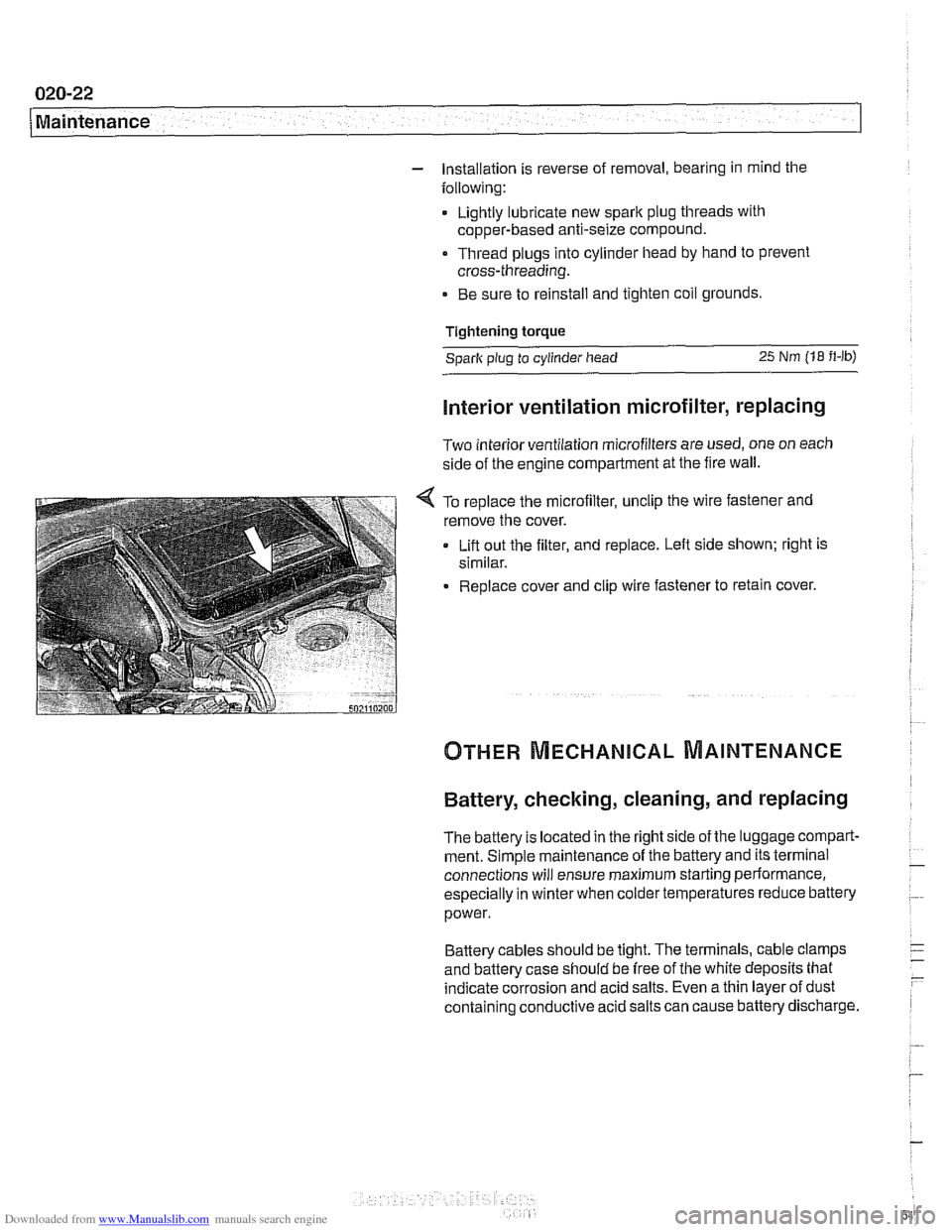
< To replace the microfilter, unclip the wire fastener and
remove the cover.
Lift out the filter, and replace. Left side shown; right is
similar.
Replace cover and clip wire fastener to retain cover.
Battery, checking, cleaning, and replacing
The battery Is located in the right side of the luggage compart-
ment. Simple maintenance of the battery and its terminal
connections will ensure maximum starting periormance,
especially in winter when colder temperatures reduce battery
power.
Battery cables should be tight. The terminals, cable clamps
and battery case should be free of the white deposits that
indicate corrosion and acid salts. Even a thin layer of dust
containing conductive acid salts can cause battery discharge.
Page 63 of 1002
Downloaded from www.Manualslib.com manuals search engine
Maintenance
BODY AND INTERIOR MAINTENANCE
Body and hinges, lubricating
Door locksand loclccylinderscan be lubricated with an oil that
contains graphite.
Body and doorhinges, hood latch and doorcheclc rods should
be lubricated with
SAE 30 or SAE 40 engine oil. Lubricate
seat runners with multipurposegrease. Do not apply any oil to
rubber parts.
If door weather-strips are sticking, lubricate
them with silicone spray or talcum powder. The hood release
cable should be lubricated as well.
The use of winter
lock deicer sprays should be lkept to an
absolute minimum, as the alcohol in the deicer will wash the
grease out of the lock assemblies and may cause locks to
corrode internally or to become difficult to operate.
Exterior washing
The longer dirt is left on the paint, the greater the risk of dam-
aging theglossy finish,
eitherby scratching or by thechemical
effect dirt particles may have on the painted surface.
Do not wash the car in direct sunlight. If the engine hood is
warm, allow it to cool. Beads of water not only leave spots
when dried rapidly by the sun or heat from theengine, but also
can act as small magnifying glasses and burn spots into the
finish. Wash the car with a mixture of lukewarm water and a
car wash product. Rinse using plenty of clear water. Wipe the
body dry with a sofl cloth towel or chamois to prevent
water-spotting.
Interior care
Dirt spots can usually be removed with lultewarm soapy water
or a dry foam cleaner. Use spot remover for grease and oil
spots. Do not pour the liquid directly on the carpet or fabric,
but dampen a clean cloth and rub carefully, starting at the
edge of the spot and working inward. Do not use gasoline,
naphtha, or other flammable substances.
Leather upholstery and trim
Leather upholstery and trim should be periodically cleaned
using a slightly damp cotton or wool cloth. The idea is to get
rid of the dirt in the creases and pores that can cause brittle-
ness and premature aging. On heavily soiled areas, use a
mild detergent (such as
wooliteQ) or other specially formulat-
ed leather cleaners. Dry the trim and upholstery completely
Page 68 of 1002
Downloaded from www.Manualslib.com manuals search engine
Engine-General
This section covers system descriptions and general informa-
tion on engines and engine management systems. Also cov-
ered is basic engine troubleshooting.
For specific repair procedures, refer to the appropriate repair
group:
110 Engine Removal and Installation
0 113 Cylinder Head Removal and Installation
116 Cylinder Head and Valvetrain
0 117 Camshaft Timing Chain
119 Lubrication System
120 Ignition System
130 Fuel Injection
0 170 Radiator and Cooling System
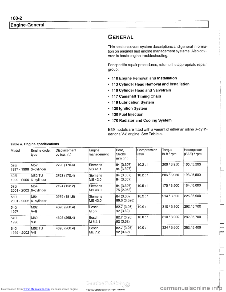
E39 models are fitted with a variant of either an inline 6-cylin-
der or a
V-8 engine. See Table a.
Table a. Engine specifications
Page 69 of 1002
Downloaded from www.Manualslib.com manuals search engine
Engine identifying features
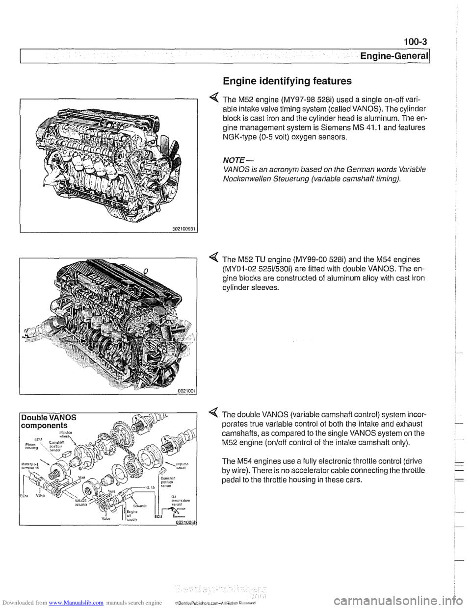
4 The M52 engine (MY97-98 528i) used a single on-off vari-
able intake valve timing system (called VANOS). The cylinder
block is cast iron and the cylinder head is aluminum. The en-
gine management system is Siemens MS 41
.I and features
NGK-type (0-5 volt) oxygen sensors.
NOTE-
VANOS is an acronym based on the German words Variable
Nocltenwellen Steuerung (variable camshaft timing).
4 The M52 TU engine (MY99-00 5281) and the M54 engines
(MY01-02 525il530i) are fitted with double VANOS. The en-
gine
blocits are constructed of aluminum alloy with cast iron
cylinder sleeves.
4 The double VANOS (variable camshaft control) system incor-
porates true variable control of both the
intake and exhaust
camshafts, as compared to the single VANOS system on the
M52 engine
(onloff control of the intaite camshaft only).
The M54 engines use a fully electronic throttle control (drive
by wire). There is no accelerator cable connecting the throttle
pedal to the throttle housing in these cars.
Page 70 of 1002
Downloaded from www.Manualslib.com manuals search engine
100-4
I Engine-General
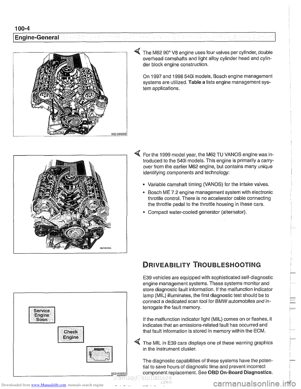
The M62 90" V8 engine uses four valves per cylinder, double
overhead camshafts and light alloy cylinder head and cylin-
der
bloclc engine construction.
On 1997 and 1998 540i models, Bosch engine management
systems are utilized. Table a lists engine management sys-
tem applications.
4 For the 1999 model year, the M62 TU VANOS engine was in-
troduced to the 540i models. This engine is primarily a carry-
over from the earlier M62 engine, but contains many unique
identifying components and technology:
Variable camshaft timing (VANOS) for the intake valves.
Bosch ME 7.2 engine management system with electronic
throttle control. There is no accelerator cable connecting
the throttle pedal to the throttle housing in these cars.
Compact water-cooled generator (alternator).
E39 vehicles are equipped with sophisticated self-diagnostic
engine management systems. These systems monitor and
store diagnostic fault information. If the malfunction indicator
lamp (MIL) illuminates, the first diagnostic test should be to
connect a dedicated scan tool for BMW automobiles and in-
terrogate the fault memory.
If the malfunction indicator light (MIL) comes on orflashes, it
indicates that an emissions-related fault has occurred and
that fault information is stored in memory within the ECM.
4 The MIL in E39 cars displays one of these warning graphics
in the instrument cluster.
The diagnostic capabilities of these systems have the poten-
tial to save hours of diagnostic time and prevent incorrect
5 placement. See OBD On-Board Diagnostics.
Page 72 of 1002
Downloaded from www.Manualslib.com manuals search engine
100-6
( Engine-General
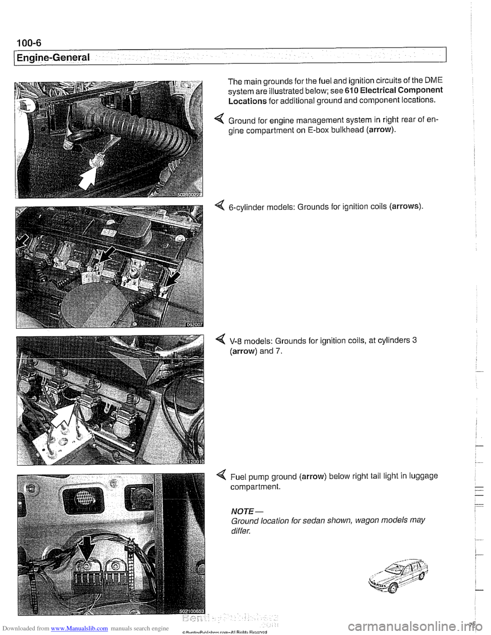
The main grounds for the fuel and ignition circuits of the DME
system are illustrated below; see 610 Electrical Component
Locations for additional ground and component locations.
4 Ground for engine management system in right rear of en-
gine compartment on E-box bulkhead (arrow).
6-cylinder models: Grounds
for ignition coils (arrows)
4 V-8 models: Grounds for ignition coils, at cylinders 3
(arrow) and 7.
4 Fuel pump ground (arrow) below right tail light in luggage
compartment.
NOTE-
Ground location for sedan shown, wagon models may
differ.
Page 73 of 1002
Downloaded from www.Manualslib.com manuals search engine
11 0 Engine Removal and installation
General ........................... .I1 0-2 Engine, Removal and Installation
........................ Special tools .I 10-2 (V-8 models). ..................... 11 0-1 6
Engine, Removal and Installation
....................... (6-cylinder) .I1 0-3
Page 75 of 1002
Downloaded from www.Manualslib.com manuals search engine
110-3
Engine Removal and lnstallationl
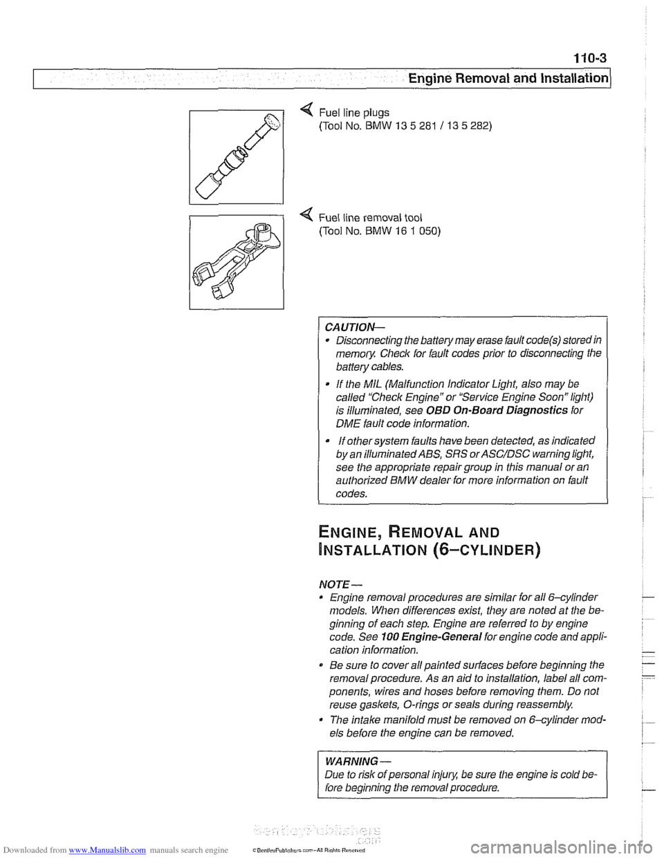
Q Fuel line plugs
(Tool No.
BMW 13 5 281 / 13 5 282)
4 Fuel line removal tool
(Tool No.
BMW 16 1 050)
CAUTION-
Disconnecting the battery may erase fault code@) storedin
memoiy Check for fault codes prior to disconnecting the
battery cables.
If the MIL (Malfunction Indicator Light, also may be
called "Check Engine" or "Service Engine Soon" light)
is illuminated, see
OBD On-Board Diagnostics for
DME fault code information.
It orhersysrem faults have been detected, as indicated I
by an ~llum~nated ABS, SRS orASC/DSC ~arning light,
see the appropriate repair group in this manual or an
authorized BMW dealer for more information on fault
codes.
NOTE- Engine removal procedures are similar for all 6-cylinder
models. When differences
exist, they are noted at the be-
ginning of each step. Engine are referred to by engine
code. See
100 Engine-General for engine code and appli-
cation information.
@ Be sure to cover all painted surfaces before beginning the
removal procedure. As an aid to installation, label all com-
ponents, wires and hoses before removing them. Do not
reuse
gaskets, O-rings or seals during reassembly.
The
intake manifold must be removed on &cylinder mod-
els before the engine can be removed.
WARNING-
Due to risk of personal injury, be sure the engine is cold be-
fore beginning the removal procedure.
Page 77 of 1002
Downloaded from www.Manualslib.com manuals search engine
Engine Removal and lnstallationl
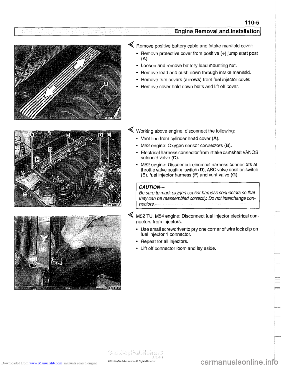
< Remove positive battery cable and intake manifold cover:
Remove protective cover from positive (+)jump start post
(4.
Loosen and remove battery lead mounting nut.
Remove lead and push down through intake manifold
Remove trim covers
(arrows) from fuel injector cover.
Remove cover hold down bolts and lift off cover.
Working above engine, disconnect the following:
Vent line from cylinder head cover (A).
M52 engine: Oxygen sensor connectors (8).
Electrical harness connector from intalte camshaft VANOS
solenoid valve
(C).
M52 engine: Disconnect electrical harness connectors at
throttle valve position switch
(D), ASC valve position switch
(E), fuel injector harness (F) and vent valve (G).
CAUTION-
Be sure to mark oxygen sensor harness connectors so that
they can be reassembled correctly Do not interchange con-
nectors.
4 M52 TU, M54 engine: Disconnect fuel injector electrical con-
nectors from injectors.
Use small screwdriverto pry one corner of wire lock clip on
fuel injector
1 connector.
Repeat for all injectors.
Lifl off connector loom and lay aside.
Page 82 of 1002
Downloaded from www.Manualslib.com manuals search engine
.-
-6val and Installation -
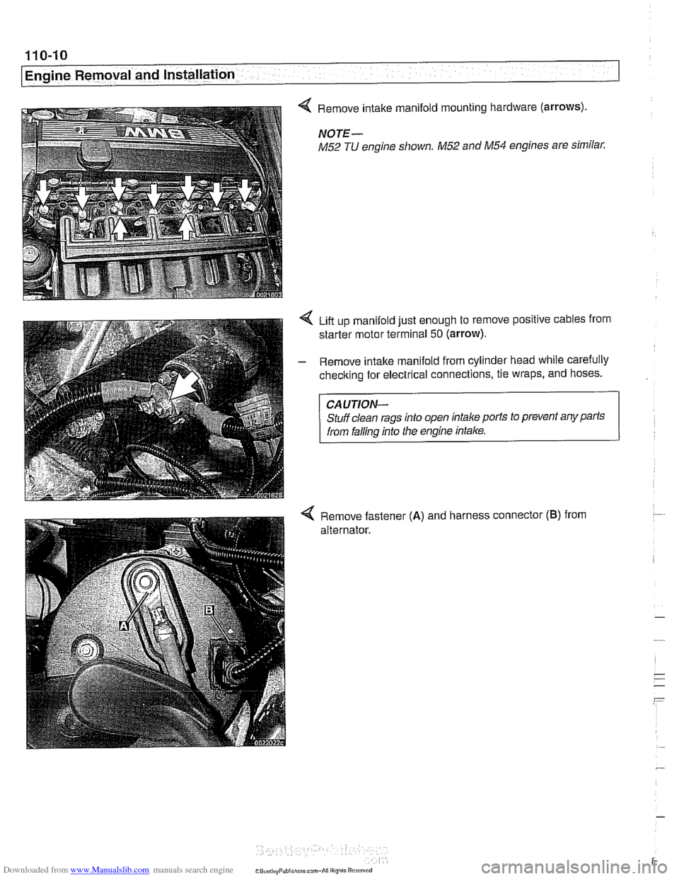
< Remove intake manifold mounting hardware (arrows).
NOTE-
M52 TU engine shown. M52 and M54 engines are similar.
Liit up manifold just enough to remove positive cables from
starter motor terminal
50 (arrow).
- Remove intake manifold from cylinder head while carefully
checking for electrical connections, tie wraps, and hoses.
CAUTION-
Stuff clean rags into open intake ports to prevent any parts
from falling into the engine intake.
4 Remove fastener (A) and harness connector (B) from
alternator.