Interior BMW 540i 1999 E39 Owner's Manual
[x] Cancel search | Manufacturer: BMW, Model Year: 1999, Model line: 540i, Model: BMW 540i 1999 E39Pages: 1002
Page 460 of 1002
Downloaded from www.Manualslib.com manuals search engine
130-70
Fuel Injection
ECM relay
--
CAUTION-
Relay positions can vary Be sure to confirm relay position by
identifying the wiring in the
socl(et using the wiring diagrams
in ELE Electrical Wiring Diagrams.
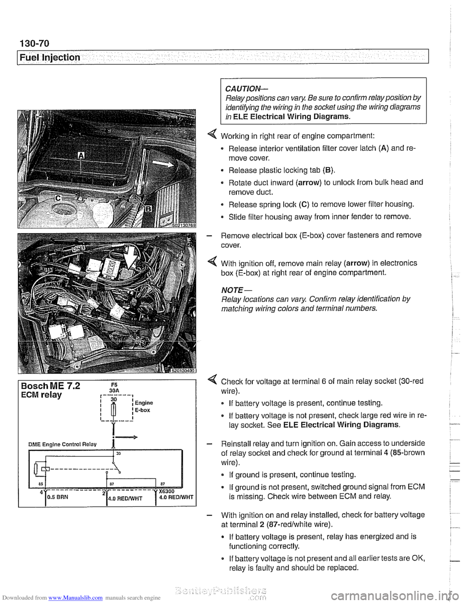
Working in right rear of engine compartment:
Release interior ventilation filter cover latch
(A) and re-
move cover.
Release plastic locking tab
(B).
Rotate duct inward (arrow) to unlock from bulk head and
remove duct.
Release spring
loclt (C) to remove lower filter housing.
Slide filter housing away from inner fender to remove.
- Remove electrical box (E-box) cover fasteners and remove
cover.
4 With ignition off, remove main relay (arrow) in electronics
box (E-box) at right rear of engine compartment.
NOTE-
Relay locations can vary Confirm relay identification by
matching wiring colors and terminal numbers.
4 Check for voltage at terminal 6 of main relay socket (30-red
wire).
If battery voltage is present, continue testing.
If battery voltage is not present, check large red wire in re-
lay socltet. See ELE Electrical Wiring Diagrams.
- Reinstall relay and turn ignition on. Gain access to underside
of relay socket and check for ground at terminal
4 (85-brown
wire).
If ground is present, continue testing.
If ground is not present, switched ground signal from ECM
is missing. Check wire between ECM and relay.
- With ignition on and relay installed, check for battery voltage
at terminal
2 (87-redlwhite wire).
If battery voltage is present, relay has energized and is
functioning correctly.
If battery voltage is not present and all earlier tests are OK.
relay is faulty and should be replaced.
Page 476 of 1002
Downloaded from www.Manualslib.com manuals search engine
.-- -
/ Fuel Tank and Fuel Pump - .. -. -- 1
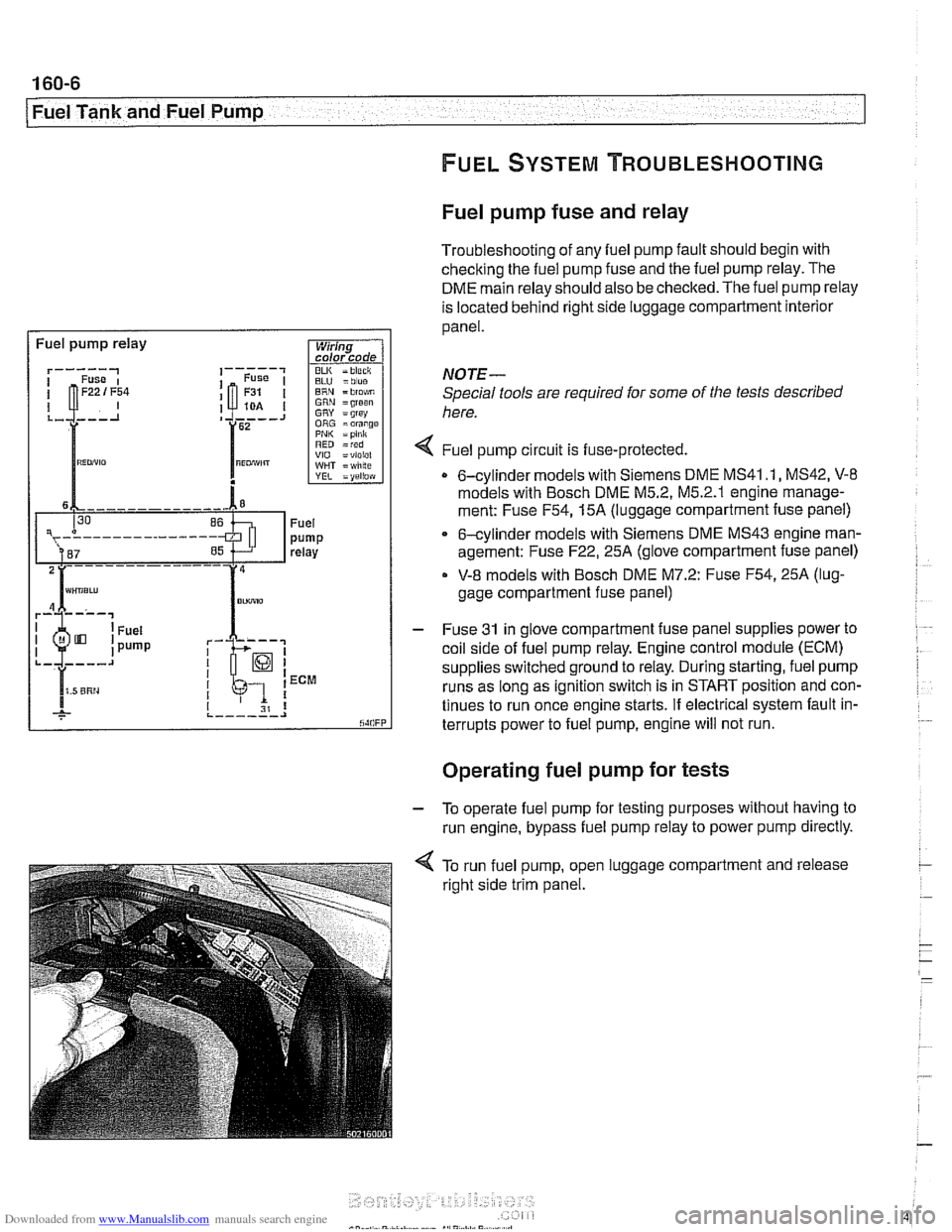
Fuel pump fuse and relay
Troubleshooting of any fuel pump fault should begin with
checking the fuel pump fuse and the fuel pump relay. The
DME main relay should also be checked. The fuel pump relay
is located behind right side luggage compartment interior
panel.
I Fuel pump relay
BLU =blue ERN = blo$,m GRN =groan GRY = grsy ORG =orange PNI< =pink RED =red VIO =violel WHT = wlilte
rk-; I I 1 ECM
I I I 31 8 ,._--___.I
NOTE-
Special tools are required for some of the tests described
here.
4 Fuel pump circu~t is fuse-protected.
0 6-cylinder models with Siemens DME MS41 .I, MS42, V-8
models with Bosch DME M5.2, M5.2.1 englne manage-
ment: Fuse
F54,15A (luggage compartment fuse panel)
6-cylinder models with Siemens DME MS43 engine man-
agement: Fuse
F22,25A (glove compartment fuse panel)
V-8 models with Bosch DME M7.2: Fuse F54,25A (lug-
gage compartment fuse panel)
- Fuse 31 in glove compartment fuse panel supplies power to
coil side of fuel pump relay. Engine control module (ECM)
supplies switched ground to relay. During starting, fuel pump
runs as long as ignition switch is in START position and con-
tinues to run once engine starts. If electrical system fault in-
terrupts power to fuel pump, engine will not run.
. .
Operating fuel pump for tests
- To operate fuel pump for testing purposes without having to
run engine, bypass fuel pump relay to power pump directly.
< To run fuel pump, open luggage compartment and release
right side trim panel.
Page 546 of 1002
Downloaded from www.Manualslib.com manuals search engine
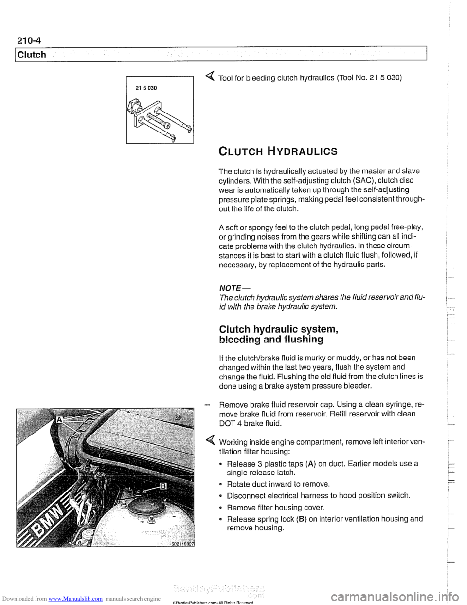
Tool for bleeding clutch hydraulics (Tool No. 21 5 030)
21 5 030 I
The clutch is hydraulically actuated by the master and slave
cylinders. With the self-adjusting clutch
(SAC), clutch disc
wear is automatically taken up through the self-adjusting
pressure plate springs, making pedal feel consistent through-
out the life of the clutch.
A soft or spongy feel to the clutch pedal, long pedal free-play,
or grinding noises
from the gears while shifting can all indi-
cate problems with the clutch hydraulics. In these circum-
stances it is best to
star? with a clutch fluid flush, followed, if
necessary, by replacement of the hydraulic parts.
NOTE-
The clutch hydraulic system shares the fluid reservoir and flu-
id with the brake hydraulic system.
Clutch hydraulic system,
bleeding and flushing
If the clutchlbralte fluid is murky or muddy, or has not been
changed within the last two years, flush the system and
change the fluid. Flushing the old fluid from the clutch lines is
done using a bralte system pressure bleeder.
- Remove brake fluid reservoir cap. Using a clean syringe, re-
move brake fluid from reservoir. Refill reservoir with clean
DOT
4 bralte fluid.
Worlting inside engine compartment, remove left
interiorven-
tilation filter housing:
Release 3 plastic taps
(A) on duct. Earlier models use a
single release latch.
Rotate duct inward to remove.
Disconnect electrical harness to hood position switch.
Remove filter housing cover.
Release spring lock
(B) on interior ventilation housing and
remove housing.
Page 548 of 1002
Downloaded from www.Manualslib.com manuals search engine
21 0-6
1 Clutch
Hydraulic system, bleeding
(using
BMW special tool 21 5 030)
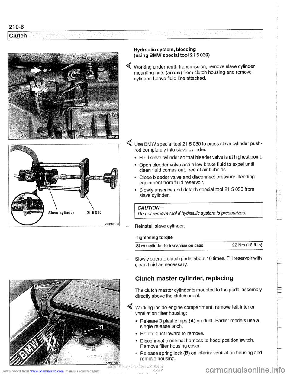
4 Working underneath transmission, remove slave cylinder
mounting nuts (arrow) from clutch housing and remove
cylinder. Leave fluid line attached.
4 Use BMW special tool 21 5 030 to press slave cylinder push-
rod completely into slave cylinder.
Hold slave cylinder so that bleeder valve is at highest point.
Open bleeder valve and allow brake fluid to expel until
clean fluid comes out, free of air bubbles.
* Close bleeder valve and disconnect pressure bleeding
equipment from fluid reservoir.
Slowly unscrew and detach special tool 21
5 030 from
slave cylinder.
CAUTION-
Do not remove tool if hydraulic system is pressurized.
- Reinstall slave cylinder.
Tightening torque Slave cylinder to transmission case
22 Nm (1 6 ft-lb)
- Slowly operate clutch pedal about 10 times. Fill reservoir with
clean fluid as necessary.
Clutch master cylinder, replacing
The clutch master cylinder is mounted to the pedal assembly
directly above the clutch pedal.
Working inside engine compartment, remove left interior
ventilation filter housing:
Release 3 plastic taps
(A) on duct. Earlier models use a
single release latch.
Rotate duct inward to remove
Disconnect electrical harness to hood position switch.
Remove filter housing cover.
Release spring
loclc (B) on interior ventilation housing and
remove housing.
Page 550 of 1002
Downloaded from www.Manualslib.com manuals search engine
21 0-8
Clutch
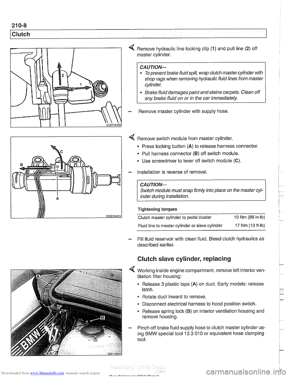
4 Remove hydraulic line locking clip (1) and pull line (2) off
master cylinder.
CAUTION-
. To prevent brake fluidspill, wrap clutch master cylinder with
shop rags when removing hydraulic fluid lines from master
cylinder.
* Brake fluid damages paint andstains carpets. Clean off
any brake fluid on or
in the car immediately.
- Remove master cylinder with supply hose
4 Remove switch module from master cylinder.
Press locking button
(A) to release harness connector.
Pull harness connector
(8) off switch module.
Use screwdriver to lever
off switch module (C).
- Installation is reverse of removal.
CA UTlON-
Switch module must snap firmly into place on the master cyl-
inder during installation.
Tightening torques
Clutch master cylinder to pedal cluster
10 Nm (89 in-lb)
Fluid line
to master cylinder or slave cylinder 17 Nm (13 ft-lb)
- Fill fluid reservoir with clean fluid. Bleed clutch hydraulics as
described earlier.
Clutch slave cylinder, replacing
4 Working inside engine compartment, remove left interiorven-
tilation filter housing:
Release
3 plastic taps (A) on duct. Early models: release
latch.
Rotate duct inward to remove.
Disconnect electrical harness to hood position switch.
Release spring lock (B) on interior ventilation housing and
remove housing.
- Pinch off brake fluid supply hose to clutch master cylinder us-
ing BMW special tool
13 3 01 0 or equivalent hose clamping
tool.
Page 771 of 1002
Downloaded from www.Manualslib.com manuals search engine
Brakes
Brakes, bleeding
The procedure below requires a BMW Service Tester (DIS-
pluslGTl/MoDiC).
- Determine type of traction control (ASC, DSC with precharge
pump, DSC without precharge pump). Be sure to use correct
specification brake fluid, according to application table below.
Brake fluid applications
ABS I ASC and ABS / DSC models DOT 4 brake fluid
with precharge pump (to 911998)
ABS I DSC models without precharge DOT 4 low viscosity
pump (911998 and later) brake
fluid
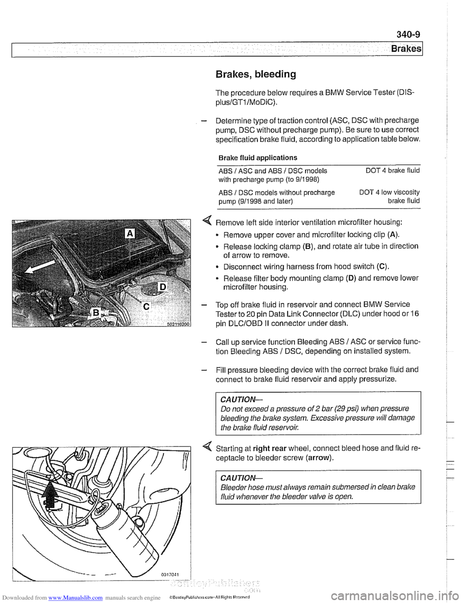
< Remove left side interior ventilation microfilter housing:
Remove upper cover and microfilter loclting clip
(A).
Release locking clamp (B), and rotate air tube in direction
of arrow to remove.
Disconnect wiring harness from hood switch
(C).
Release filter body mounting clamp (D) and remove lower
microfilter housing.
- Top off bralte fluid in reservoir and connect BMW Service
Tester to
20 pin Data Link Connector (DLC) under hood or 16
pin
DLCIOBD I1 connector under dash.
- Call up service function Bleeding ABS / ASC or service func-
tion Bleeding ABS
/ DSC, depending on installed system.
- Fill pressure bleeding device with the correct brake fluid and
connect to brake fluid reservoir and apply pressurize.
Do not exceed a pressure of
2 bar (29 psi) when pressure
bleeding the
brake system. Excessive pressure will damage
4 Starting at right rear wheel, connect bleed hose and fluid re-
ceptacle to bleeder screw (arrow).
CA UTlON-
Bleeder hose must always remain submersed in clean brake
fluid whenever the bleeder valve is open.
Page 779 of 1002
Downloaded from www.Manualslib.com manuals search engine
Brakes
Master cylinder, removing and installing
CAUTlOI\C
Brake fluid is highly corrosive and dangerous to the environ-
ment. Dispose of it properly.
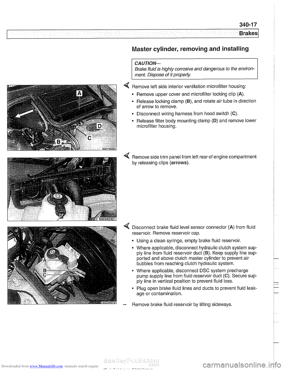
4 Remove left side interior ventilation microfilter housing:
Remove upper cover and microfilter locking clip
(A).
- Release locking clamp (B), and rotate air tube in direction
of arrow to remove.
Disconnect wiring harness from hood switch
(C).
Release filter body mounting clamp (D) and remove lower
microfilter housing.
4 Remove side trim panel from left rear of engine compartment
by releasing clips
(arrows).
4 Disconnect bralte fluid level sensor connector (A) from fluid
reservoir. Remove reservoir cap.
. Using a clean syringe, empty bralte fluid reservoir.
Where applicable, disconnect hydraulic clutch system sup-
ply line from fluid reservoir duct
(5). Keep supply line sup-
ported and above clutch master cylinder to prevent air
bubbles from reaching clutch hydraulic system.
Where applicable, disconnect DSC system precharge
pump supply line from fluid reservoir duct
(C). Secure sup-
ply line in vertical position to prevent fluid loss.
Plug open brake fluid lines and ducts to prevent fluid leak-
age or contamination.
- Remove brake fluid reservoir by tilting sideways.
Page 783 of 1002
Downloaded from www.Manualslib.com manuals search engine
1 Brakes
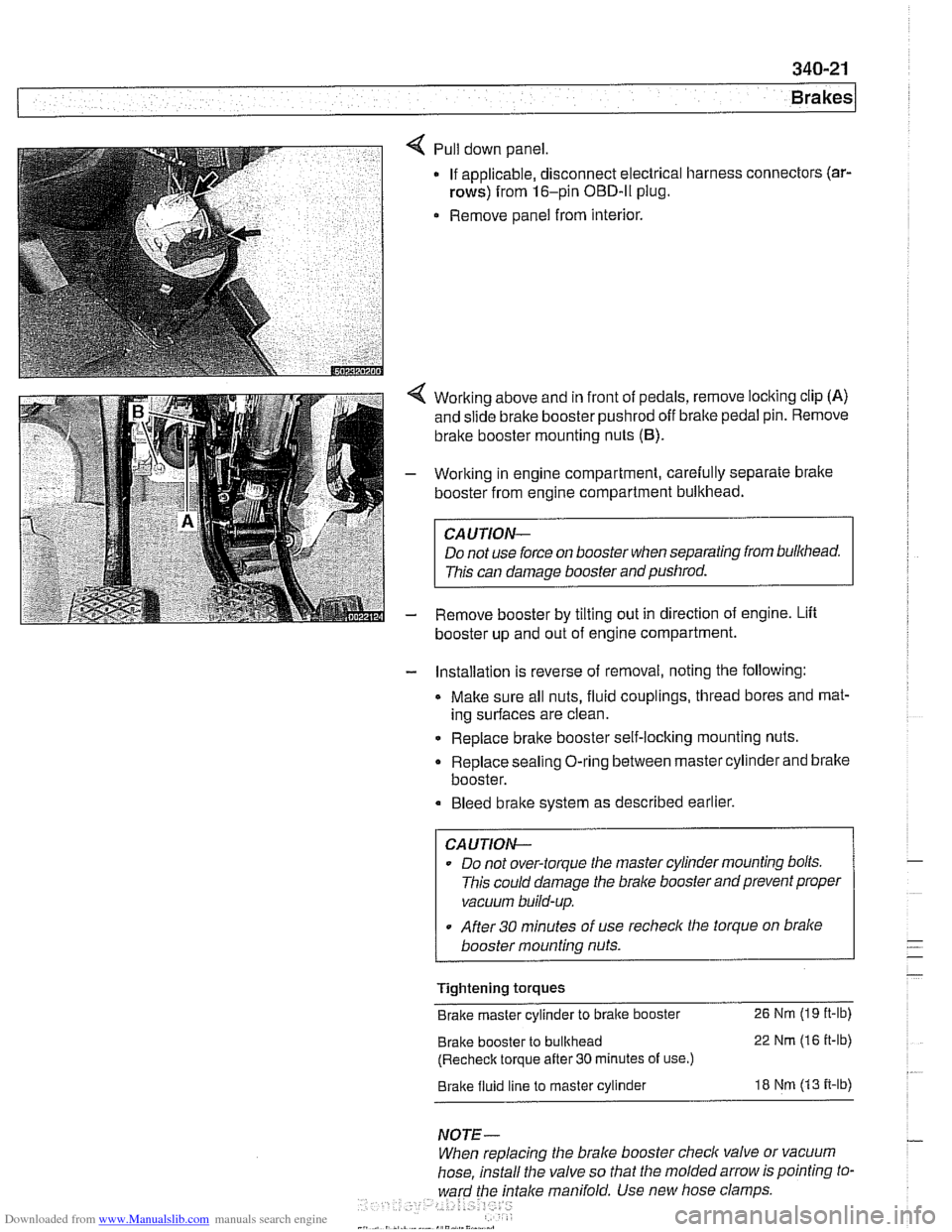
Pull down panel
If applicable, disconnect electrical harness
rows) from 16-pin OBD-ll plug.
Remove panel from interior. connectors
(ar-
Working
above and in front of pedals, remove locking clip (A)
and slide brake booster pushrod off bralte pedal pin. Remove
brake booster mounting nuts
(6).
Working in engine compartment, carefully separate bralte
booster from engine compartment bulkhead.
CAUTION-
Do not use force on booster when separating from bulkhead.
This can damage booster and pushrod.
Remove booster by tilting out in direction of engine. Lift
booster up and out of engine compartment.
- Installation is reverse of removal, noting the following:
Make sure all nuts, fluid couplings, thread bores and mat-
ing surfaces are clean.
Replace bralte booster self-locking mounting nuts.
Replace sealing O-ring between master cylinder and bralte
booster.
Bleed bralte system as described earlier.
CAUTION--
Do not over-torque tlie master cylinder mounting bolts.
This could damage the
bralce booster and prevent proper
vacuum build-up.
After
30 minutes of use recheclc the torque on bralce
booster mounting nuts.
Tightening torques
Brake master cylinder to brake booster
26 Nm (19 it-lb)
Brake booster to bulkhead 22 Nm (16 it-lb)
(Recheck torque after
30 minutes of use.)
Brake fluid line to master cylinder 18 Nm (13 it-lb)
NOTE-
When replacing the brake booster check valve or vacuum
hose, install the valve so that the molded arrow is pointing to-
ward the
fntalce manifold. Use new hose clamps
Page 795 of 1002
Downloaded from www.Manualslib.com manuals search engine
400 Body-General
........................ General ........................... .40 0.2 Roof paddin~ 400-7
Body Assembly ................... .40 0.2
Body dimensions (in inches)
............ .40 0.2
Bodyshell
........................... 400-3
Exterior and aerodynamics
............. .40 0.3
Sport Wagon ...................... .40 0.4
Tailgate
............................ .40 0.5
Tailgate lock system
.................. .40 0.5
Rear wiper system ................... .40 0.6
Antenna and sound system ............ .40 0.6
Safety and Security Features ....... .40 0.7
Safety cage
......................... .40 0.7
Door locks and door handles
........... .40 0.7
.
........................... Seat belts 400-7
Airbags ............................ 400-8
Battery safety terminal (BST)
........... 400-9
Security
............................ 400-9
Interior Features ................... 400-9
............................. Seats 400-10
Instruments and controls .............. 400-10
Central body electronics
.............. 400-1 1
Heating and Air
Conditioning (IHKA)
............... 400-12
Page 799 of 1002
Downloaded from www.Manualslib.com manuals search engine
400-5
Body-General
Tailgate
The E39 Sporl Wagon tailgate is large with a low sill for easy
cargo loading. The tailgate opens to an angle of
88" mea-
sured from the rear roof pillar (D-pillar) and to a height of
2029
mm (79.8 in) measured from the ground to the upper edge of
the raised tailgate.
The rear window is bonded to a load bearing frame and can
be opened separately from the main tailgate. Tailgatesupport
gas springs are recessed into cavities in the roof.
Tailgate lock system
A mechanical tailgate lock cylinder is not used; the tailgate is
opened by the unlock pad above the license plate, the remote
tailgate switch located in the drivers kick panel, or via
FZV
(Iteyless entry) control.
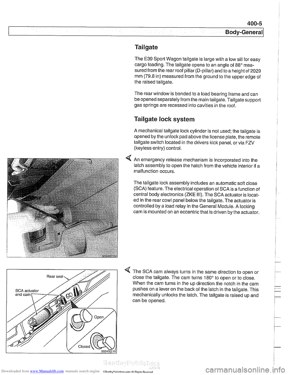
4 An emergency release mechanism is incorporated into the
latch assembly to open the hatch from the vehicle interior if a
malfunction occurs.
The tailgate lock assembly includes an automatic soft close
(SCA) feature. The electrical operation of SCA is a function of
central body electronics
(ZKE Ill). The SCA actuator is locat-
ed in the rear cowl panel below the tailgate. The actuator is
controlled by a load relay in the General Module. A locking
cam is mounted on an eccentric that is driven by the actuator.
4 The SCA cam always turns in the same direction to open or
close the tailgate. The cam turns
180" to open or to close.
When the cam turns in the up direction the notch in the cam
SCA actuator pushes on a lever on the back of the latch in the tailgate. This
mechanically unlocks the latch. The tailgate is raised up and
can be opened.