Timing BMW 540i 2000 E39 Workshop Manual
[x] Cancel search | Manufacturer: BMW, Model Year: 2000, Model line: 540i, Model: BMW 540i 2000 E39Pages: 1002
Page 317 of 1002
Downloaded from www.Manualslib.com manuals search engine
Camshaft Timing chain1 - -- -
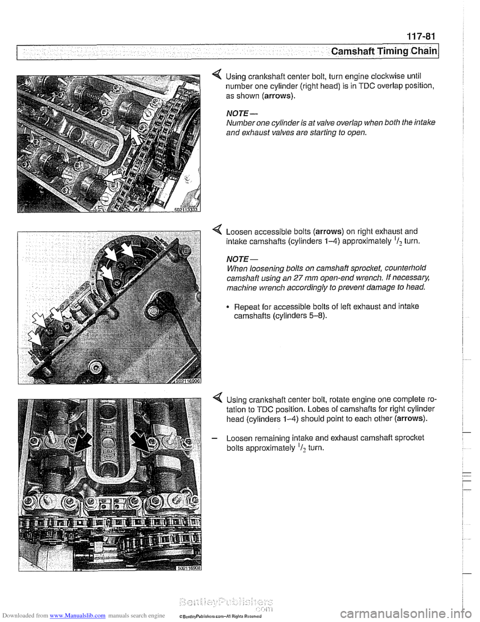
Using crankshaft center bolt, turn engine clockwise until
number one cylinder (right head) is in
TDC overlap position,
as shown
(arrows).
NOTE-
Number one cylinder is at valve overlap when both the intale
and exhaust valves are starting to open.
< Loosen accessible bolts (arrows) on right exhaust and
intake camshafts (cylinders
1-4) approximately 'I2 turn.
NOTE-
When loosening bolts on camshaft sprocket, counterhold
camshaft using an
27 mm open-end wrench. If necessary.
machine wrench accordingly to prevent damage
to head.
Repeat for accessible bolts of left exhaust and intake
camshafts (cylinders
5-8).
Using crankshaft center bolt, rotate engine one complete ro-
tation to
TDC position. Lobes of camshafts for right cylinder
head (cylinders
1-4) should point to each other (arrows).
- Loosen remaining intake and exhaust camshaft sprocltet
bolts approximately
'I2 turn.
Page 318 of 1002
Downloaded from www.Manualslib.com manuals search engine
[camshaft Timina Chain Cylinders
1-4
11 2445 11 2 441
502116429;
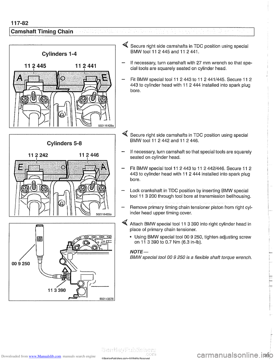
Secure right side camshafts in TDC position using special
BMWtoolll 2445andll 2441.
- If necessary, turn camshaft with 27 mm wrench so that spe-
cial tools are squarely seated on cylinder head.
- Fit BMW special tool 11 2 443 to 11 2 4411445. Secure 11 2
443
to cylinder head with 11 2 444 installed into spark plug
bore.
I
< Secure right side camshafts in TDC position using special
Cylinders 5-8 BMW tool 11 2 442 and 11 2 446.
- If necessary, turn camshaft so that special tools are squarely
seated on cylinder head.
- Fit BMW special tool 11 2 443 to 11 2 4421446. Secure 11 2
443
to cylinder head with 11 2 444 installed into spark plug
bore.
- Lock cranltshaft in TDC position by inserting BMW special
tool
11 3 200 through tool bore at transmission bellhousing.
- Remove primary timing chain tensioner piston from right cyl-
~nder head upper timing cover.
4 Attach BMW special tool 11 3 390 into right cylinder head in
place of primary chain tensioner.
Using BMW special tool
00 9 250, tighten adjusting screw
on
11 3 390 to 0.7 Nm (6.3 in-lb).
NOTE-
BMW special fool 00 9 250 is a flexible shaft torque wrench.
Page 319 of 1002
Downloaded from www.Manualslib.com manuals search engine
Camshaft Timing chain/
- Tighten accessible sprocket retaining bolts in the following
order:
Leit exhaust camshaft
Right exhaust
camshait
Leit intake camshaft
Right
intalte camshait
Tightening torque
Sprocket bolts to camshaft flange
15 Nm (1 1 ft-lb)
- Remove BMW special tool 11 2 300 from tool bore at bell-
housing and remove
camshaft loclting tools from cylinder
heads.
Using crankshaft center bolt, turn engine over clockwise at
least one
comolete rotation so that remainino camshaft
sprocltet
retaking bolts are accessible. -
- Tighten remaining camshait sprocket retaining bolts
Tightening torque Sprocket bolts to camshaft
flange 15 Nm (I 1 It-lb)
- Remove BMW special tool 11 3 390 from primary timing
chain tensioner bore and reinstall primary chain tensioner
- Remainder of installation is reverse or removal, noting the fol-
lowing:
Remove gasket residue from cylinder head sealing sur-
face.
Apply a thin bead of Three Bond 1209
O sealing com-
pound to joints at cylinder head cover and timing case cov-
er and at half-moon sections at rear of cylinder heads.
Replace cylinder head cover
gaskets if necessary.
Page 332 of 1002
Downloaded from www.Manualslib.com manuals search engine
119-12
Lubrication System 1
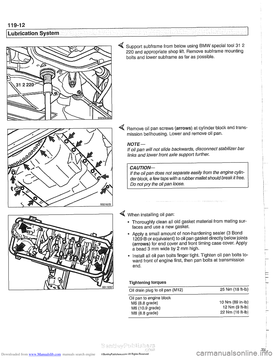
4 Support subframe from below using BMW special tool 31 2
220 and appropriate shop lift. Remove
subframe mounting
bolts and lower
subframe as far as possible.
Remove oil pan screws (arrows) at cylinder block and trans-
mission bellhousing. Lower and remove oil pan.
NOTE-
If oil pan will not slide backwards, disconnect stabilizer bar
links and lower front axle support further.
If the oil pan does not separate easily from the engine cylin-
der
block, a few taps with a rubber malletshould breakit free.
Do not
pry the oil pan loose.
When installing oil pan: Thoroughly clean all old gasket material from mating sur-
faces and use a new gasket.
Apply a small amount of non-hardening sealer
(3 Bond
12098 or equivalent) to oil pan gasket directly below joints
(arrows) for end cover and front timing case cover. Apply
a bead
3 mm wide by 2 mm high.
Install all oil pan bolts finger tight. Tighten oil pan bolts to-
ward front of engine first, then pan bolts at transmission
end.
Tightening
torques
Oil drain plug to oil pan (M12) 25 Nm (18 ft-lb)
Oil pan to engine block
MG (8.8 grade)
MG (10.9 grade)
M8 (8.8 grade)
10 Nm (89 In-lb)
12 Nm (9 ft-lb)
22 Nrn (16 R-lb)
Page 353 of 1002
Downloaded from www.Manualslib.com manuals search engine
Lnition switch
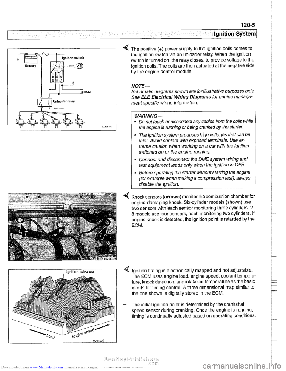
4 The positive (+) power supply to the ignition coils comes to
the ignition switch via an unloader relay. When the ignition
switch is turned on, the relay closes, to provide voltage to the
ignition coils. The coils are then actuated at the negative side
by the engine control module.
NOTE-
Schematic diagrams shown are for illustrative purposes only.
See ELE Electrical Wiring Diagrams for engine manage-
ment specific wiring information.
WARNING- Do not touch or disconnect any cables from the coils while
the engine is running or being cranked by the starter:
The ignition system produces high voltages that can be
fatal. Avoid contact with exposed terminals. Use ex-
treme caution when
working on a car with the ignition
switched on or the engine running.
* Connect and disconnect the DME system wiring and
test equipment leads only when the ignition is
OFF
Before operating the starter without starting the engine
(for example when
making a compression test), always
disable the ignition.
4 Knock sensors (arrows) monitor the combustion chamber for
engine-damaging knock. Six-cylinder models (shown) use
two sensors with each sensor monitoring three cylinders.
V-
8 models use four sensors, each monitoring two cylinders. If
engine
knock is detected, the ignition point is retarded by the
ECM.
I Ignition advance Ignition timing is electronically mapped and not adjustable.
The ECM uses engine load, engine speed, coolant tempera-
ture, knock detection, and intake air temperature as the basic
inputs for timing control.
A three dimensional map similar to
the one shown is digitally stored in the ECM.
- The initial ignition point is determined by the crankshaft
speed sensor during cranking. Once the engine is running.
timing is continually adjusted based on operating conditions.
Page 364 of 1002
Downloaded from www.Manualslib.com manuals search engine
120-1 6
Ignition System
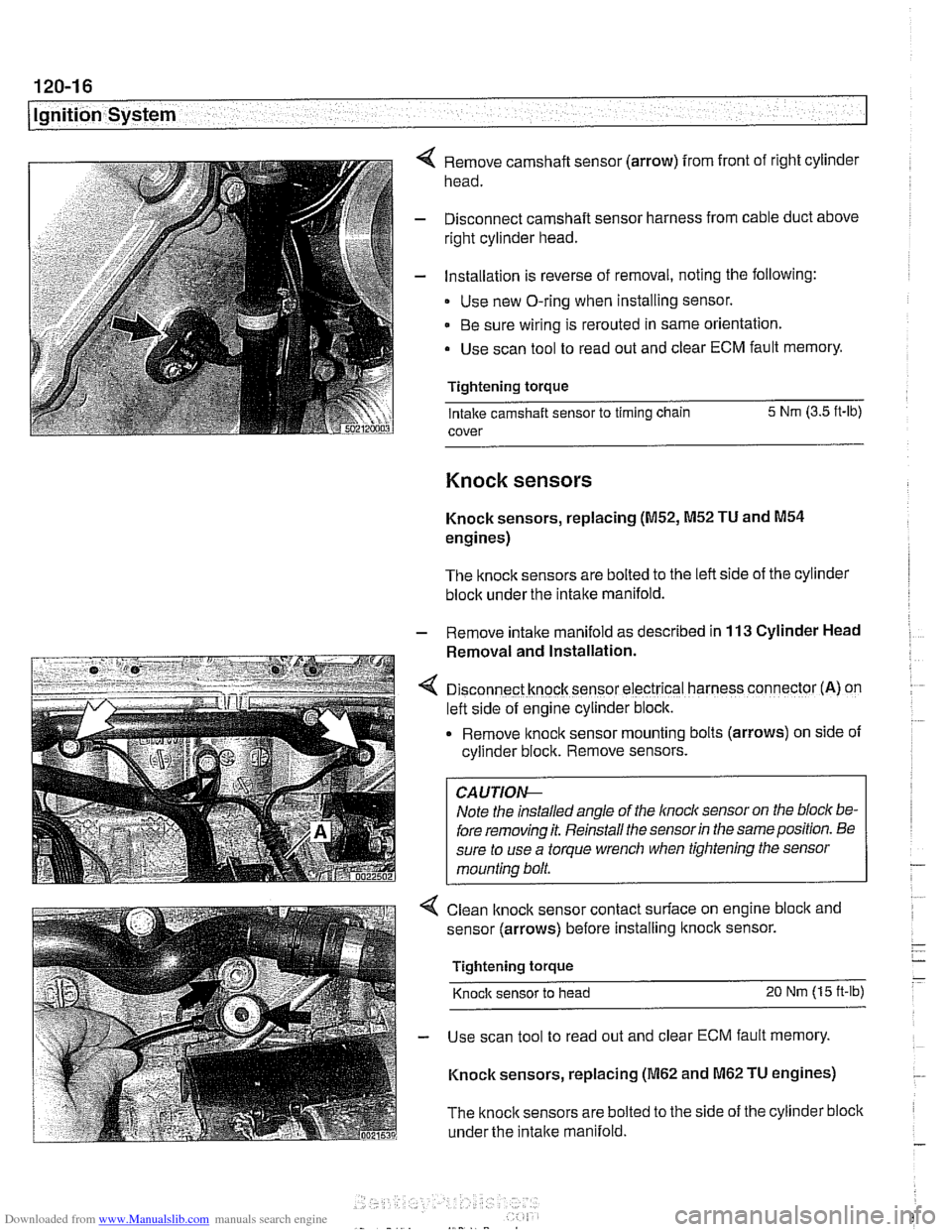
Remove camshaft sensor (arrow) from front of right cylinder
head.
Disconnect camshaft sensor harness from cable duct above
right cylinder head.
Installation is reverse of removal, noting the following:
Use new O-ring when installing sensor.
Be sure wiring is rerouted in same orientation.
Use scan tool to read out and clear ECM fault memory.
Tightening torque Intake camshaft sensor to timing chain 5 Nm
(3.5 ft-lb)
cover
Knock sensors
Knock sensors, replacing (M52, M52 TU and M54
engines)
The knock sensors are bolted to the left side of the cylinder
block under the intake manifold.
- Remove intalte manifold as described in 113 Cylinder Head
Removal and Installation.
D~sconnect knock sensor electrical harness connector (A) on
left side of engine cylinder block.
Remove knock sensor
mount~ng bolts (arrows) on side of
cyllnder block. Remove sensors.
Note the installed angle of the
lnocl~ sensor on the bloc/( be-
fore removing it. Reinstall the sensor
in the same position. Be
sure to use a torque wrench when tightening the sensor
mounting bolt.
< Clean lknock sensor contact surface on engine bloclc and
sensor (arrows) before installing
ltnock sensor.
Tightening torque
Knock sensor to head 20 Nm (15 ft-lb)
- Use scan tool to read out and clear ECM fault memory.
Knock sensors, replacing
(M62 and M62 TU engines)
The
knock sensors are bolted to the side of the cylinder block
under the
intake manifold.
Page 400 of 1002
Downloaded from www.Manualslib.com manuals search engine
130-1 0
Fuel Injection
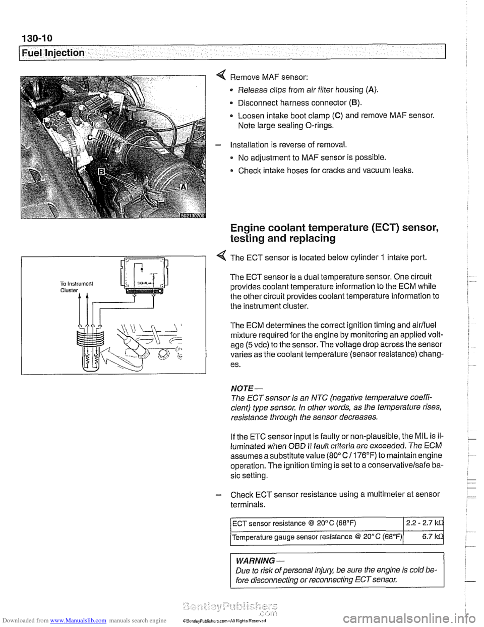
Remove MAF sensor:
Release clips from air filter housing
(A).
Disconnect harness connector (B).
Loosen intake boot clamp (C) and remove MAF sensor.
Note large sealing O-rings.
Installation is reverse of removal.
No adjustment to MAF sensor is possible.
Check intake hoses for cracks and vacuum leaks.
Engine coolant temperature (ECT) sensor,
testing and replacing
R
1 -4 The ECT sensor is located below cylinder 1 intake port
The ECT sensor is a dual temperature sensor. One circuit
provides coolant temperature information to the ECM while
the other circuit provides coolant temperature information to
the instrument cluster.
The ECM determines the correct ignition timing and
airlfuel
mixture required for the engine by monitoring an applied volt-
age
(5 vdc) to the sensor. The voltage drop across the sensor
varies as the coolant temperature (sensor resistance) chang-
es.
NOTE-
The ECT sensor is an NTC (negative temperature coeffi-
cient) type sensor. in other words, as the temperature rises,
resistance through the sensor decreases.
If the ETC sensor input is faulty or non-plausible, the MIL is il-
luminated when
OED II fault criteria are exceeded. The ECM
assumes asubstitute value
(80°C1 176°F) to maintainengine
operation. The ignition timing is set to a
conse~ativelsafe ba-
sic setting.
- Check ECT sensor resistance using a multimeter at sensor
terminals.
-
WARNING -
Due to risk of personal injury, be sure the engine is cold be-
fore disconnecting or reconnecting ECT sensor.
ECT sensor resistance @ 20" C (68°F) 2.2 - 2.7
Temperature gauge sensor resistance @ 20°C (~B"F)( 6.7 k
Page 420 of 1002
Downloaded from www.Manualslib.com manuals search engine
Fuel Injection
Engine coolant temperature
(ECT) sensor,
testing and replacing
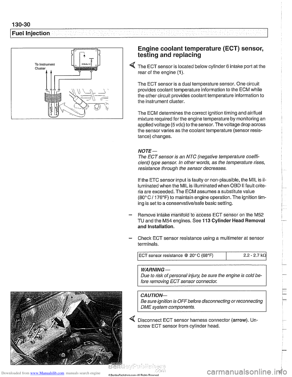
4 The ECT sensor is located below cylinder 6 intake port at the
rear of the engine (1).
The ECT sensor is a dual temperature sensor. One circuit
provides coolant temperature information to the ECM while
the other circuit provides coolant temperature information to
the instrument cluster.
The ECM determines the correct ignition timing and airlfuel
mixture required
forthe engine temperature by monitoring an
appliedvoltage
(5vdc) to the sensor.Thevoltage drop across
the sensor varies as the coolant temperature (sensor resis-
tance) changes.
NOTE-
The ECT sensor is an NTC (negative temperature coeffi-
cient) type sensor. In other words, as the temperature rises,
resistance through the sensor decreases.
If the ETC sensor input is faulty or non-plausible, the MIL is il-
luminated when the MIL is illuminated when
OED II fault crite-
ria are exceeded. The ECM assumes a substitute value
(80" C 11 76'F) to maintain engine operation. The ignition tim-
ing is set to a
conservativelsafe basic setting.
- Remove intake manifold to access ECT sensor on the M52
TU and the M54 engines. See 113 Cylinder Head Removal
and Installation.
- Check ECT sensor resistance using a multimeter at sensor
terminals.
WARNING -
Due to rislc of personal injury, be sure the engine is cold be-
fore removing ECT sensor connector.
ECT sensor resistance @ 20°C (68°F)
CAUTIOI\C
Be sure ignition is OFFbefore disconnecting or reconnecting
DME svstem components.
2.2 - 2.7 k
4 Disconnect ECT sensor harness connector (arrow). Un-
screw ECT sensor from cylinder head.
Page 421 of 1002
Downloaded from www.Manualslib.com manuals search engine
Fuel Injection
- Installation is reverse of removal:
Use new copper sealing washers when installing sensor.
Replace any lost coolant.
Tightening torque
Temperature sensor to cylinder head
13 Nm (10 ft-lb)
Intake air temperature (IAT) sensor,
testing and replacing
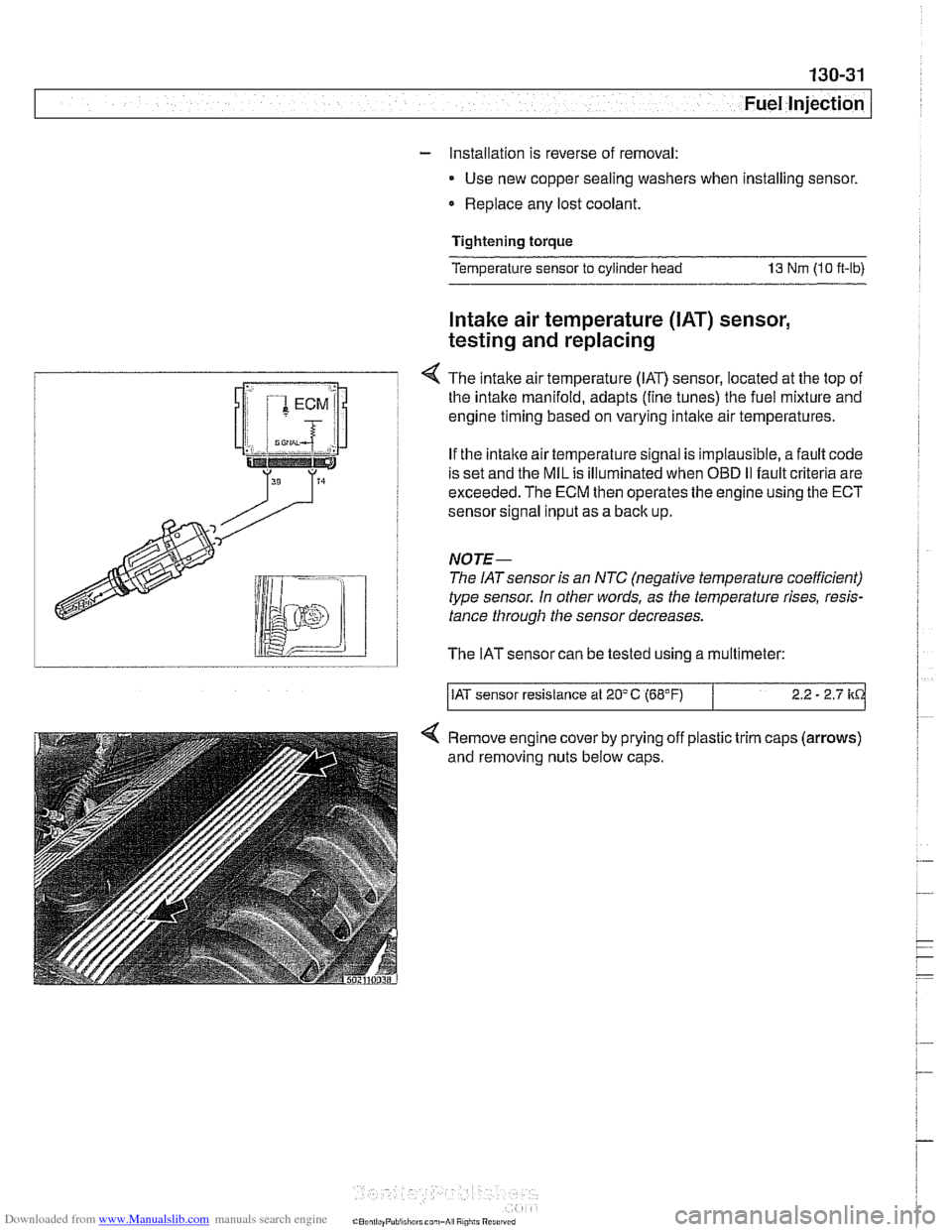
4 The intake airtemperature (IAT) sensor, located at the top of
I the intake manifold, adapts (fine tunes) the fuel mixture and i
T engine timing based on varying intake air temperatures.
i If the intaite air temperature signal is implausible, a fault code
! is set and the MIL is illuminated when OBD I1 fault criteria are
I exceeded. The ECM then operates the engine using the ECT
i sensor sional inout as a back uo.
type sensor. In other words,
a> the temperature rises, resis-
tance through the sensor decreases.
lid I The IATsensor can be tested using a multimeter:
/IAT sensor resistance at 20'C (68°F) 2.2 - 2.7 kd
Remove engine cover by prying off plastic trim caps (arrows)
and removing nuts below caps.
Page 445 of 1002
Downloaded from www.Manualslib.com manuals search engine
Fuel Injection
- If voltage is present as described above, check wiring be-
tween ECM and valve. If no wiring faults are found, check
ECM signal to valve.
- When replacing idle speed control valve, clean and inspect
all sealing areas.
. Inspect sealing ring in throttle body and replace if neces-
sary.
Throttle position sensor (TPS),
testing and replacing
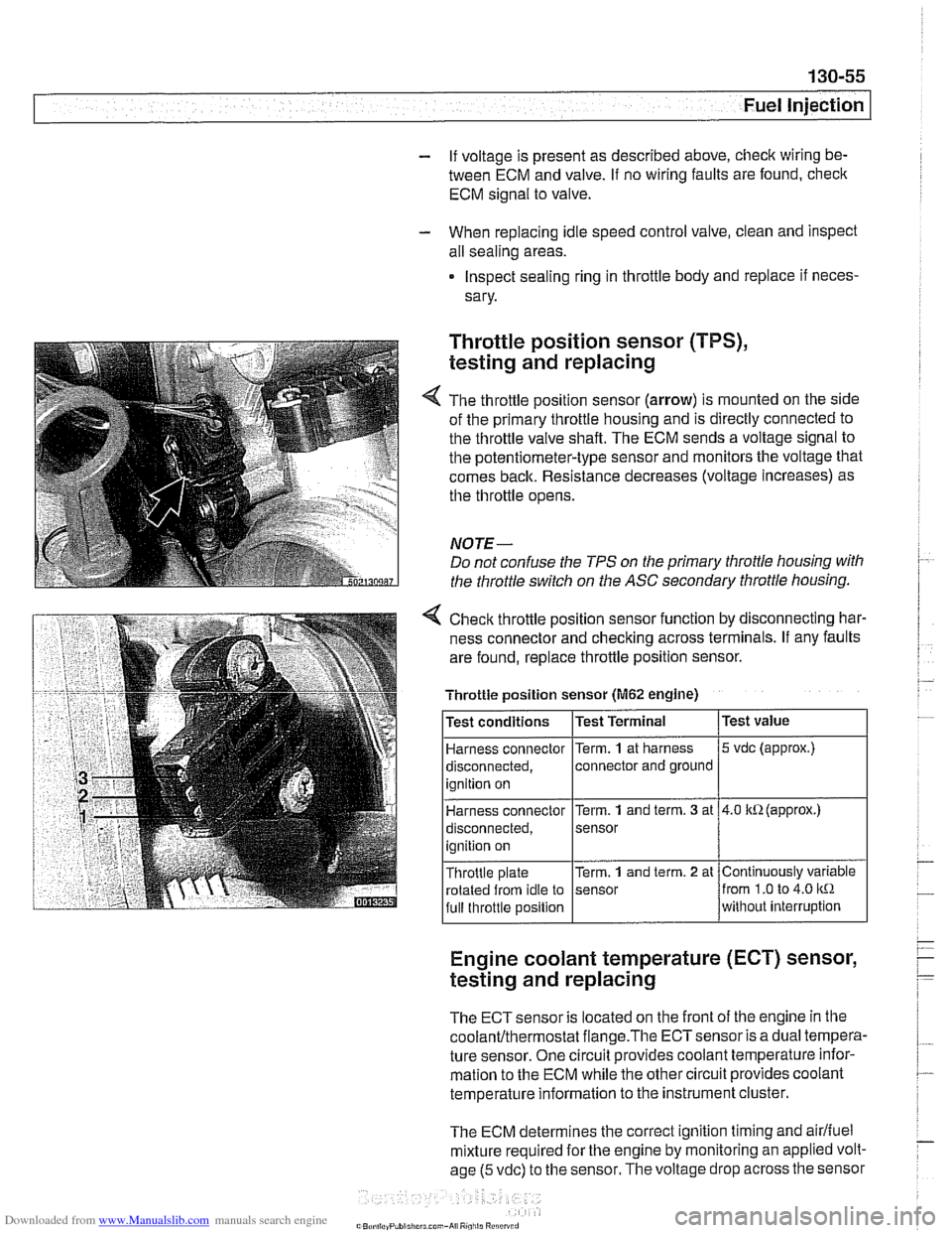
The throttle position sensor (arrow) is mounted on the side
of the primary throttle housing and is directly connected to
the throttle valve shaft. The ECM sends a voltage signal to
the potentiometer-type sensor and monitors the voltage that
comes back. Resistance decreases (voltage increases) as
the throttle opens.
NOTE-
Do not confuse the TPS on the primary throttle housing with
the throttle switch on the
ASC secondary throttle housing.
4 Check throttle position sensor function by disconnecting har-
ness connector and checking across terminals. If any faults
are found, replace throttle position sensor.
Engine coolant temperature (ECT) sensor,
testing and replacing
Throttle position sensor (M62 engine)
The ECT sensor is located on the front of the engine in the
coolanVthermostat flange.The ECTsensor is a dual tempera-
ture sensor. One circuit provides coolant temperature infor-
mation to the ECM while the other circuit provides coolant
temperature information to the instrument cluster.
The ECM determines the correct ignition timing and
airlfuel
mixture required for the engine by monitoring an applied volt-
age
(5 vdc) to the sensor. The voltage drop across the sensor
Test
value
5 vdc (approx.)
4.0 kR(approx.)
Continuously variable
from
1.0 to 4.0 kR
without interruption
Test
conditions
Harness connector
disconnected, ignition on
Harness connector
disconnected,
ignition on
Throttle plate rotated from idle to
full throttle position Test Terminal
Term.
1 at
harness
connector and ground
Term.
1 and term. 3 at
sensor
Term.
1 and term. 2 at
sensor