oil change BMW 540i 2000 E39 User Guide
[x] Cancel search | Manufacturer: BMW, Model Year: 2000, Model line: 540i, Model: BMW 540i 2000 E39Pages: 1002
Page 58 of 1002
Downloaded from www.Manualslib.com manuals search engine
020-26
Maintenance
NOTE-
The parking brake may lose some of its effectiveness if it is
not used frequently This is due to corrosion build-up on the
parking brake drum. To remove corrosion, apply the parking
brake just until it begins to grip, then pull the lever up one
more stop (click). Drive the car approximately 400 meters
(1,300
ft.) and release the brake. To recheck the adjustment
of the parking brake see
340 Brakes.
Clutch fluid, checking
In cars equipped with manual transmission and clutch, the hy-
draulic clutch and the brake system share the same reservoir
and the same bralte fluid. Clutch fluid level and brake fluid lev-
el are checked at the same time.
NOTE-
* See 340 Brakes for more information.
See
210 Clutch for information on the clutch and the
hydraulic clutch operating system.
Differential oil level, checking
The E39 differential is filled with lifetime oil that ordinarily
does not need to be changed.
BMW recommends using only
a specially formulated synthetic gear oil
(SAF-XO) that is
available through an authorized
BM\N dealer parts depart-
ment. For additional information on this lubricant and any
other lubricants that may be compatible, contact an
authorized
BMW dealer service department.
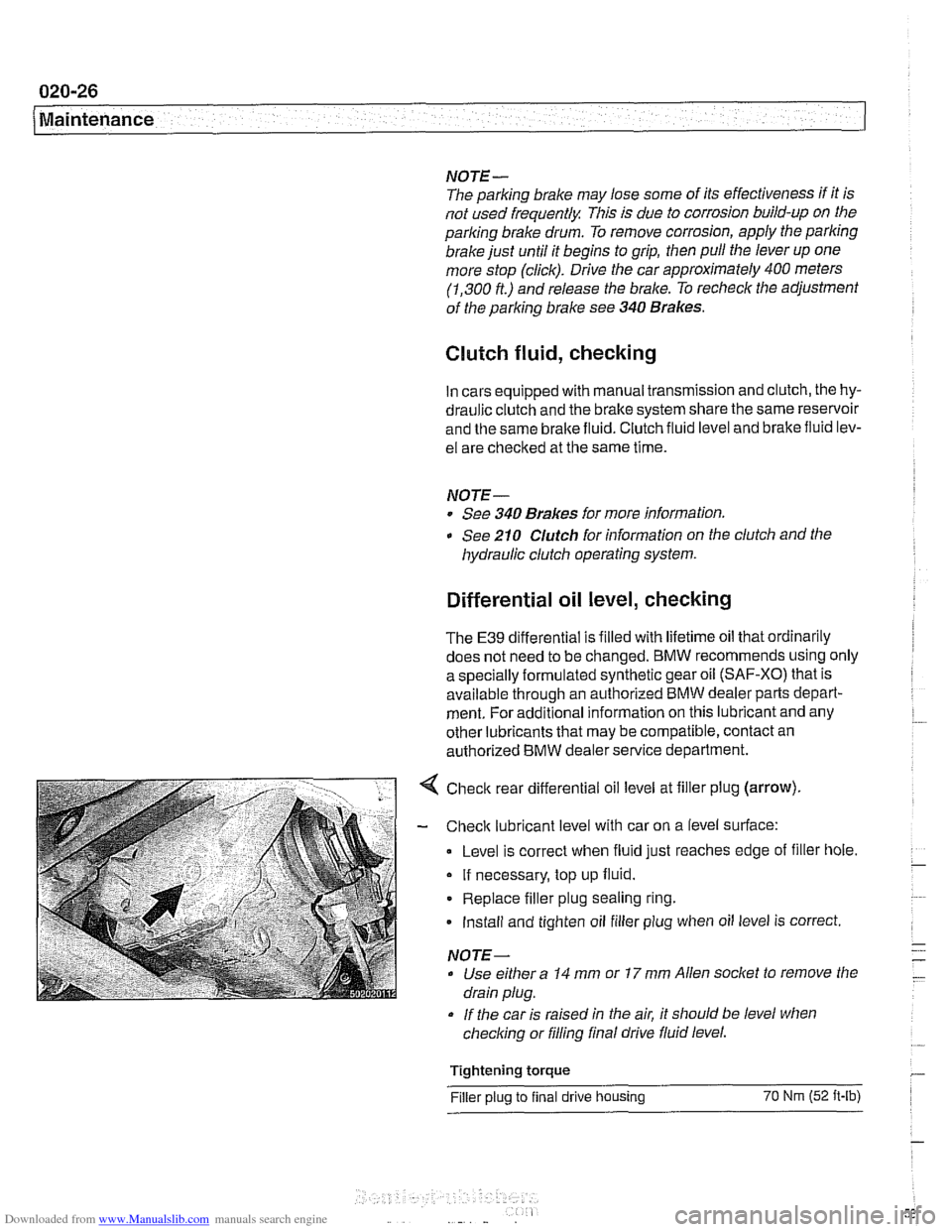
< Check rear differential oil level at filler plug (arrow).
- Check lubricant level with car on a level surface:
Level is correct when fluid just reaches edge of filler hole.
If necessary, top up fluid.
Replace filler plug sealing ring.
Install and tighten oil filler plug when oil level is correct.
NOTE-
Use either a 14 mm or 17 mm Allen socket to remove the
drain plug.
If the car is raised in the air, it should be level when
checking or filling final drive fluid level.
Tightening torque
Filler plug to final drive housing 70 Nrn (52 it-lb)
Page 61 of 1002
Downloaded from www.Manualslib.com manuals search engine
Maintenance
Suspension, front, inspecting
Inspection of the front suspension and steering includes a
check of all moving parts
forwear and excessive play. Inspect
ball joint and tie-rod rubber seals and boots for cracks
ortears
that could allow the entry of dirt, water, and other
contaminants. See
310 Front Suspension.
Suspension, rear, inspecting
Differential and rear drive axle service consists of checking
and changing the gear oil, inspecting for leaks, and checking
the drive axle
CV joint boots for damage.
The areas where
lealts are most likely to occurare around the
drive shaft and drive axle mounting flanges. For more infor-
mation on identifying oil leaks and theircauses, see
330 Rear
Suspension and
331 Final Drive.
Tires, checking inflation pressure
Correct tire pressures are important to handling and stability,
fuel economy, and tire wear. Tire pressures change with tem-
perature. Pressures should be
checked oRen during season-
al temperature changes. Correct inflation pressures can be
found on the driver's door pillar and in the owner's manual.
Note that tire pressures should be higher when the car is
more heavily loaded.
WARNING-
Do not inflate any tire to a pressure higher than the tire's max-
imum inflation pressure listedon the sidewall. Use care when
adding air to warm tires. Warm tire pressures can increase as
much as
4 psi (0.3 bar) over their coldpressures.
Tires, rotating
BMW does not recommend tire rotation. Due to the car's sus-
pension design, the front tires begin to wear first at the outer
shoulder and the reartires begin to wearfirst at the middle of
the tread or inner shoulder. Rotating the tires may adversely
affect road handling and tire grip.
Transmission service, automatic
The automatic transmissions installed in E39 models are
filled with special automatic transmission fluid. The transmis-
sion lubricant type can be found on the "type-plate" on the
side of the transmission. The recommended lubricants are
listed earlier in this repair group. See Fluids and lubricants.
If in doubt, consult an authorized BMW dealer for alternate
Page 62 of 1002
Downloaded from www.Manualslib.com manuals search engine
020-30
Maintenance
fluid use and the most-up-to-date information regarding
transmission operating fluids.
The automatic transmission is not equipped with a dipstick.
Therefore, checking the ATF level is an involved procedure
which includes measuring and maintaining a specified ATF
temperature during the checking procedure.
For more complete
ATF service information, including
checking
ATF level and ATF filter replacement procedures,
see
240 Automatic Transmission.
Transmission service, manual
Manual transmission service consists of inspecting for leaks
and checking the fluid. Evidence of transmission leaks is
like-
ly to be seen around the driveshaft mounting flange and at the
bottom of the bellhousing.
NOTE-
For more information on identifying oil
leaks and their
causes, see 230 Manual Transmission and210 Clutch.
Transmission fluid, checking and filling
(manual transmission)
Tne manual transmss'on inslalleo 'n rne E39 models s f;lled
with a special liierime iluid (ivlTF-LT-I). oi. ordinarily
does
not need to be changed.
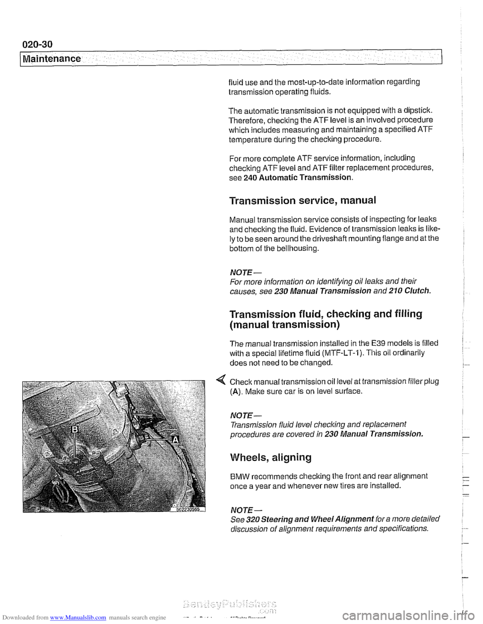
< Check manual transmission oil level at transmission filler plug
(A). Make sure car is on level surface.
NOTE- Transmission fluid level
checking and replacement
procedures are covered in 230 Manual Transmission.
Wheels, aligning
BMW recommends checking the front and rear alignment
once a year and whenever new tires are installed.
NOTE-
See 320 Steering and Wheel Alignment for a more detailed
discussion of alignment requirements and specifications.
Page 87 of 1002
Downloaded from www.Manualslib.com manuals search engine
110-15
Engine Removal and lnstallation
- Installation is reverse of removal, noting the following:
Replace all gaskets. O-rings and seals.
Use new fuel injector seals
Check that engine drive belts properly engage pulley
grooves.
Inspect O-ring seal between mass air flow sensor and air
filter housing. To facilitate reassembly, coat seal with acid-
free grease.
Change engine oil and filter and
check all other fluid levels.
See
020 Maintenance.
Refill and bleed cooling system. See
170 Radiator and
Cooling System.
CAUTION--
When reattaching throttle assembly harness connectoc con-
nector is
fuNy tightened when arrows on connector and plug
line up.
Tightening torques
Coolant drain plug to cylinder block
25 Nm (18 ft-lb)
Engine mount to
subframe (M10) 45 Nm (33 ft-ib)
Exhaust manifold to cylinder head
M6 10 Nm (89 in-lb)
M7 or ME 20 Nm (15 ft-lb)
Intake manifold to cylinder head
M7 15 Nm (I 1 ft-lb)
ME 22 Nm (16 ft-lb)
Radiator cooling fan to coolant pump
40 Nm (30 ft-lb)
Radiator drain screw to radiator
2.5 Nm (22 in-lb)
Page 93 of 1002
Downloaded from www.Manualslib.com manuals search engine
--
-- Engine Removal and installation' -
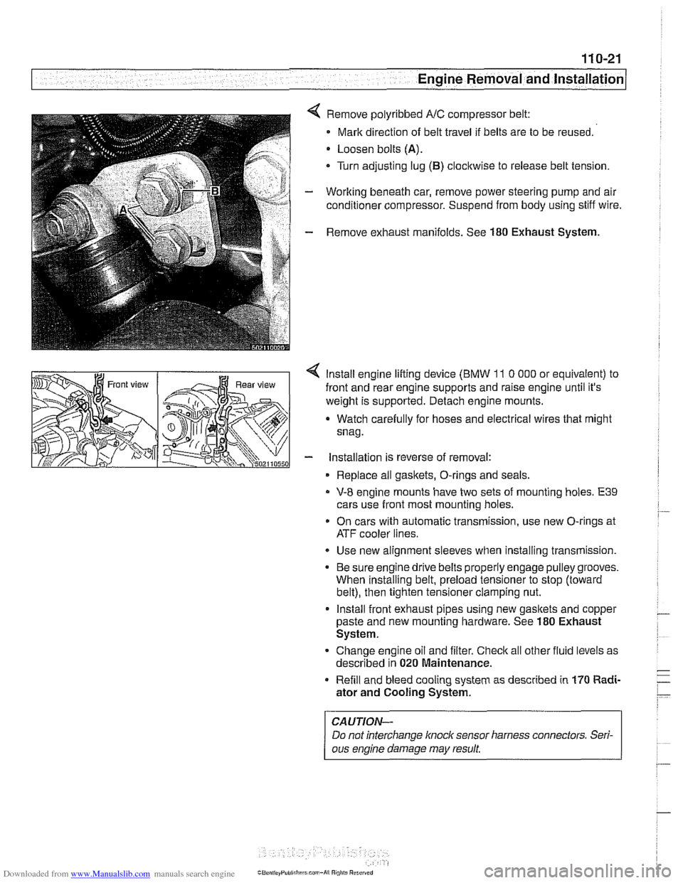
Remove polyribbed A/C compressor belt:
Mark direction of belt travel if belts are to be reused.
Loosen bolts
(A).
Turn adjusting lug (B) clocltwise to release belt tension.
Working beneath car, remove power steering pump and air
conditioner compressor. Suspend from body using stiff wire.
Remove exhaust manifolds. See
180 Exhaust System.
< lnstall engine lifting device (BMW 11 0 000 or equivalent) to
front and rear engine supports and raise engine until it's
weight is supported. Detach engine mounts.
a Watch carefully for hoses and electrical wires that might
snag.
- installation is reverse of removal:
Replace all gaskets, O-rings and seals.
V-8 engine mounts have two sets of mounting holes. E39
cars use front most mounting holes.
* On cars with automatic transmission, use new O-rings at
ATF cooler lines.
Use new alignment sleeves when installing transmission.
Be sure engine drive belts properly engage pulley grooves.
When installing belt, preload tensioner to stop (toward
belt), then tighten tensioner clamping nut.
lnstall front exhaust pipes using new gasltets and copper
paste and new mounting hardware. See
180 Exhaust
System.
Change engine oil and filter. Check all other fluid levels as
described in
020 Maintenance.
Refill and bleed cooling system as described in
170 Radi-
ator and Cooling System.
CAUTION-
Do not interchange knoclc sensor harness connectors. Seri-
ous engine damage may result
Page 101 of 1002
Downloaded from www.Manualslib.com manuals search engine
. .- . --
Lr -- - - - -- Cylinder Head Removal and Installation I -
- Release pressure at compression gauge valve, then remove
gauge from spark plug hole. Repeat test for each cylinder
and compare results with values given in Table a.
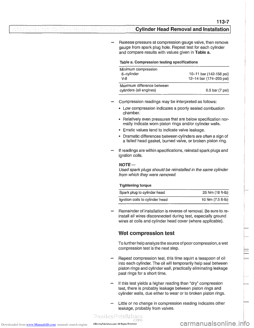
Table a. Compression testing specifications
Minimum compression
6-cylinder
10-1 1 bar (142-156 psi)
V-8 12-14 bar (174-203 psi)
Maximum difference between
cylinders (all engines)
0.5 bar (7 psi)
- Compression readings may be interpreted as follows:
Low compression indicates a poorly sealed combustion
chamber.
0 Relatively even pressures that are below specification nor-
mally indicate worn piston rings
andlor cylinder walls.
Erratic values tend to indicate valve leakage.
Dramatic differences between cylinders are often a sign of
a failed head
gasket, burned valve, or broken piston ring.
- If readings are within specifications, reinstall spark plugs and
ignition coils.
NOTE-
Used spark plugs should be reinstalled in the same cylinder
from which they were removed.
Tightening torque Spark plug to cylinder head 25 Nm
(18 ft-lb)
lanition coils to cylinder head 10 Nm (7.5 ft-lb)
- Remainder of installation is reverse of removal. Be sure to re-
install all wires disconnected during test, especially ground
wires at coils and cylinder head cover (where applicable).
Wet compression test
To further help analyze the source of poorcompression,awet
compression test is the next step.
- Repeat compression test, this time squirt a teaspoon of oil
into each cylinder. The oil will temporarily help seal between
piston rings and cylinder wall, practically eliminating leakage
past rings for a short time.
- If this test yields a higher reading than "dry" compression
test, there is probably leakage between piston rings and
cylinder walls, due either to wear or to broken piston rings.
- Little or no change in compression reading indicates other
leakage, probably from valves.
Page 115 of 1002
Downloaded from www.Manualslib.com manuals search engine
- -.
Cylinder Head Removal and lnstallation
NOTE-
Be Sure the secondary timing chain tensioner is locked down
and the exhaust
camshaif mounting bolts are loose before
proceeding.
- Install VANOS control unit. See VANOS control unit, install-
ing
(M52 engine) in 117 Camshaft Timing Chain.
CAUTION--
Incorrect installation ofthe VANOS control may result in dam-
age to the engine valvefrain.
- Install exhaust manifolds using new gaskets and nuts. Coat
manifold studs with copper paste prior to installing nuts.
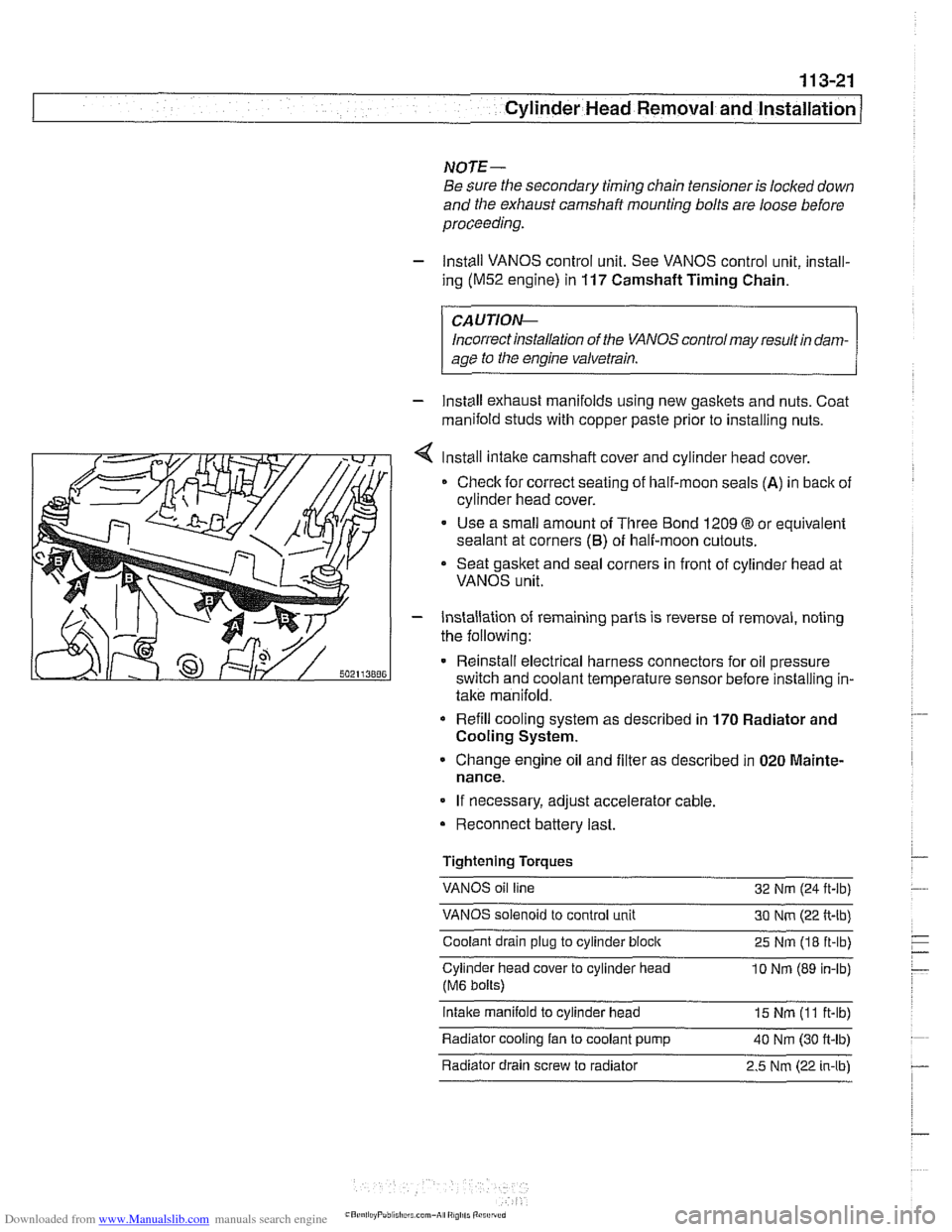
Install intake camshaft cover and cylinder
head cover.
Check for correct seating of half-moon seals
(A) in back of
cylinder head cover.
Use a small amount of Three Bond 1209
O or equivalent
sealant at corners
(6) of half-moon cutouts.
Seat gasket and seal corners in front of cylinder head at
VANOS unit.
- Installation of remaining parts is reverse of removal, noting
the following:
Reinstall electrical harness connectors for oil pressure
switch and coolant temperature sensor before installing in-
take manifold.
Refill cooling system as described in 170 Radiator and
Cooling System.
Change engine oil and filter as described in 020 Mainte-
nance.
If necessary, adjust accelerator cable.
Reconnect battery last.
Tightening Torques
VANOS oil line
32 Nm (24
ft-lb)
VANOS solenoid to control unit 30 Nm (22 ft-lb)
Coolant drain plug to cylinder
block 25 Nm (18 ft-lb)
Cylinder head cover to cylinder head
10 Nrn (89 in-lb)
(M6 bolts)
intake manifold to cylinder head 15 Nm (I 1 ft-lb)
Radiator cooling fan to coolant pump
40 Nm (30 ft-lb) - . .
Radiator drain screw to radiator 2.5 Nm (22 in-lbl
Page 127 of 1002
Downloaded from www.Manualslib.com manuals search engine
- -
-- .- Cylinder ~ead~ernoval and Installation I - -.
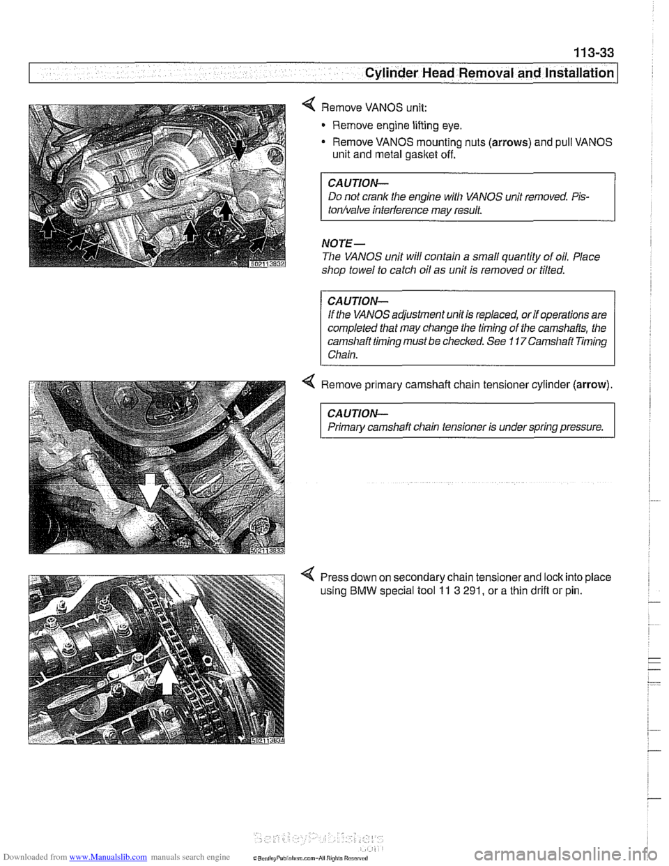
Remove VANOS unit:
Remove engine lifting eye.
- Remove VANOS mounting nuts (arrows) and pull VANOS
unit and metal gasket off.
CAUTION-
Do not crank the engine with VANOS unit removed. Pis-
tonhalve inteiference may result.
NOTE-
The VANOS unit will contain a small quantity of oil. Place
shop towel to catch oil as unit is removed or tilted.
CAUTION-
If the VANOS adjustment unit is replaced, or if operations are
completed that may change the timing of
the camshafts, the
camshaft timing must be checked. See
11 7Camshaft Timing
Chain.
4 Remove primary camshaft chain tensioner cylinder (arrow).
CAUTION-
Primary camshaft chain tensioner is under spring pressure.
Press down on secondary chain tensionerand lock into place
using
BMW special tool 11 3 291, or a thin drifl or pin.
Page 150 of 1002
Downloaded from www.Manualslib.com manuals search engine
11 3-56
I Cvlinder Head Removal and Installation
- Installation of the remaining parts is reverse or removal, not-
ing the following:
- Refill cooling system as described in 170 Radiator and
Cooling System.
Change engine oil and filter as described in
020 Mainte-
nance.
If necessary, adjust accelerator cable.
a Reconnect battery.
CAUTION- To prevent damaging the engine electronic systems, installall
ground wire previously removed, including the ground wires
for the
ionition coils.
Tightening torque Coolant drain
pluq to cylinder bloclc 25 Nm (1 8 ft-lb)
Radiator cooling fan to coolant pump 40 Nm (30 ft-lb) -
Radiator drain screw to radiator 2.5
Nm (22 in-lb)
spark plug to cylinder head 25
Nm (1 8 ft-lb)
CYLINDER MEAD REMOVAL AND
INSTALLATION (M62 ENGINE)
This procedure covers cylinder head removal and installation
for the
M62 V-8 engine. Procedures forthe M62 TU VANOS
engine are not covered in this manual.
Intake manifold, left cylinder head, and right cylinder head re-
moval and installation are written as separate procedures.
The intake manifold must be removed before the cylinder
heads can be removed.
WARNING
-
Due to risk of personal injuv be sure the engine is cold be-
fore beginning the removal procedure.
Cylinder head removal and installation requires multiple spe-
cial service tools. Read the entire procedure before beginning
the repair.
Intake manifold, removal and installation,
M62 engine
- Disconnect negative (-) battery cable.
CAUTION- Prior to disconnecting the
batterj read the baitery discon-
nection cautions
in 001 General Cautions and Warnings.
Page 166 of 1002
Downloaded from www.Manualslib.com manuals search engine
/Cylinder Head Removal and Installation
- Remainder of installation is reverse of removal, noting the fol-
lowing:
Use new gaskets when mounting intake
manifold. Tighten
nuts finger tight first, then torque to specification in stages
working diagonally from center out.
Be sure to reinstall ignition coil ground straps at cylinders
no.
3 and no. 7. See 120 Ignition System.
Reinstall cooling fan and shroud. See
170 Radiator and
Cooling System.
Refill and bleed cooling system as described in
170 Radi-
ator and Cooling System.
Change engine oil and filter as described in
020 Mainte-
nance.
CA UTIOG
To prevent damaging engine electricalsystems, be sure to in-
stall all ground wires previously removed.
Tightening torques
Camshaft sprocket to camshaft 15
Nm (11 H-lb)
Coolant manifold to cylinder head 10 Nm (7.5 H-lb)
Cylinder head cover nuts 10 Nm (7.5 ft-lb)
Exhaust manifold to head 22 Nm (17 ft-lb)
Engine mounts to subirame 42 Nm (30 ft-lb)
Spark plugs to cylinder head 22 Nm (17 ft-lb)
Right cylinder head, removing, M62 engine
- Remove left side exhaust manifold. See 180 Exhaust Sys-
tem.
- Remove intake manifold. See Intake manifold, removal
and installation,
M62 engine.
- Drain engine coolant. See 170 Radiator and Cooling Sys-
tem.
WARNING-
Use extreme caution when draining and disposing of engine
coolant.
Coolanl is poisonous andlellial lo liumans andpels.
Pets are
altracled to coolant because of 11s sfieet smell and
fasle. Seelc medcal anenfion immed~alely if coolant is ingesl-
. .-
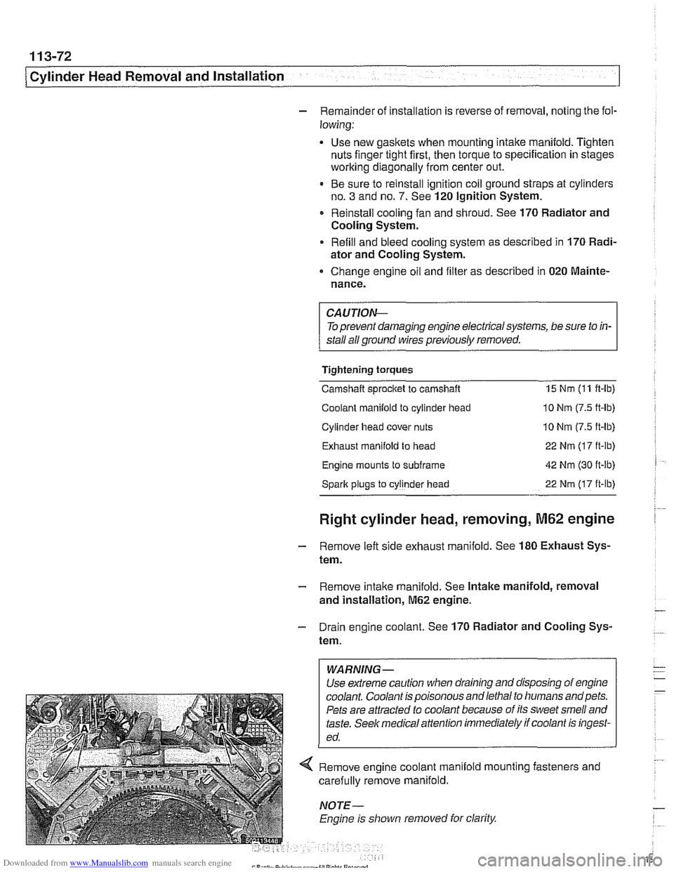
< Remove engine coolant manlold mo~nlng fasreners and
carei~lly remove manifo d.
. I
NOTE
Engine 8s slioivn removed lor clarify