torque BMW 540i 2000 E39 Workshop Manual
[x] Cancel search | Manufacturer: BMW, Model Year: 2000, Model line: 540i, Model: BMW 540i 2000 E39Pages: 1002
Page 861 of 1002
Downloaded from www.Manualslib.com manuals search engine
Exterior Trim, Bumpers
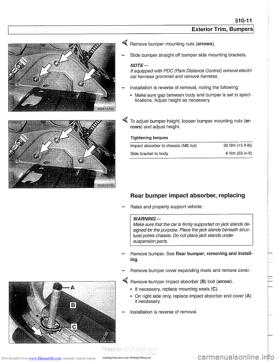
4 Remove bumper mounting nuts (arrows)
- Slide bumper straight off bumper side mounting brackets.
NOTE-
If equipped with PDC (Park Distance Control) remove electri-
cal harness grommet and remove harness.
- lnstallation is reverse of removal, noting the following:
Make sure gap between body and bumper is set to speci-
fications. Adjust height as necessary.
To adjust bumper height, loosen bumper mounting nuts (ar-
rows) and adjust height.
Tightening torques
Impact absorber to chassis (ME nut) 20 Nm (15 ft-lb)
Side bracket to body 6 Nm (53 in-it)
Rear bumper impact absorber, replacing
- Raise and properly support vehicle.
WARNING -
Make sure that the car is firmly supported on jack stands de-
signed for the purpose. Place the jack stands beneath
struc-
turalpoints chassis. Do not place jaclc stands under
suspension parts.
- Remove bumper. See Rear bumper, removing and install-
ing.
- Remove bumper cover expanding rivets and remove cover.
. - . . - . . ".-- < Remove b~mper mpact absorber (6) bot (arrow).
I If necessary, replace mounting seals (C).
- Installation is reverse of removal.
Page 862 of 1002
Downloaded from www.Manualslib.com manuals search engine
I Exterior Trim, Bumpers
Tightening torques Impact absorber to chassis
(M8 nut) 20 Nm (15 ft-lb)
Impact absorber to chassis
(M6 nut) 9 Nm (80 In-lb
Bumper bracket to impact absorber 45 Nm (32 ft-lb)
(MI0 bolt)
Front bumper height, adjusting
- A 14 mm allen socket is needed to make adjustments
- Raise and properly support vehicle.
WARNING-
Make sure that the car is firmly supported on jackstands de-
signed for the purpose. Place the jack stands beneath a
structural chassis point.
Do not place jack stands under sus-
pension parts.
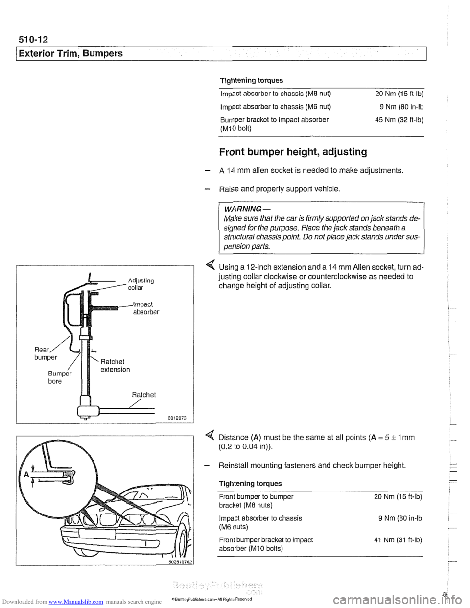
4 Using a 12-inch extension and a 14 mm Allen socket, turn ad-
justing collar
clocl~wise or counterclocl~wise as needed to
change height of adjusting collar.
4 Distance (A) must be the same at all points (A = 5 i- 1 mm
(0.2 to 0.04 in)).
- Reinstall mounting fasteners and check bumper height
Tightening torques Front bumper to bumper
20 Nm (15 ft-lb)
bracltet (M8 nuts)
Impact absorber
to chassis 9 Nm (80 in-lb
(M6 nuts)
Front bumper bracket to impact
absorber
(MI0 bolts)
41 Nm (31 ft-lb)
Page 872 of 1002
Downloaded from www.Manualslib.com manuals search engine
51 2-8
Door Windows
Door window, adjusting
Whenever the door window or window regulator is removed,
window adjustment should be checked. The glass should
contact the top of the window squarely and should seat
against the window seal uniformly.
NOTE-
If the window does not contact the window seal uniformly,
wind noise or water infiltration may result.
- Remove door panel as described in 411 Doors.
- Disconnect negative (-) cable from battery. Remove airbag
unit and vapor barrier from door. See 721 Airbag System
(SRS).
WARNING-
Prior to disconnecting the batteg read the battery discon-
nection cautions given in
001 General Warnings and
Cautions.
Longitudinal adjustment
- Adjustments are made with window in open position.
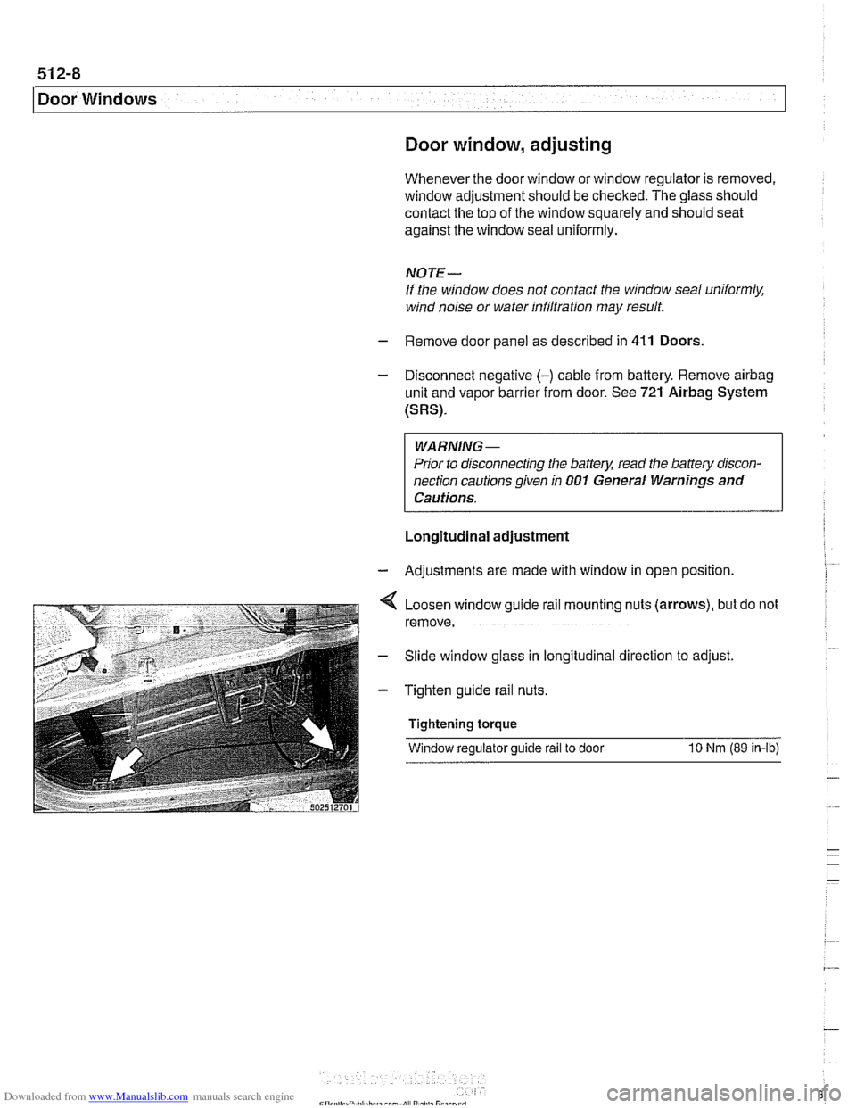
Loosen window guide rail mounting nuts (arrows), but do not
remove.
Slide window glass in longitudinal direction to adjust
Tighten guide rail nuts.
Tightening torque
Window regulator guide rail to door
10 Nrn (89 in-ib)
Page 873 of 1002
Downloaded from www.Manualslib.com manuals search engine
512-9
Door Windows
Vertical adjustment
- Adjustments are made with window in open position
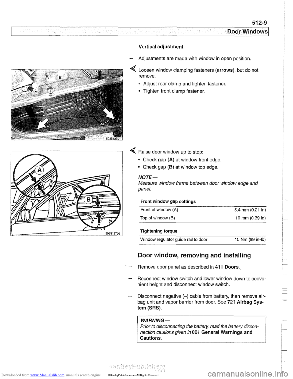
4 Loosen window clamping fasteners (arrows), but do not
remove.
Adjust rear clamp and tighten fastener.
Tighten front clamp fastener.
4 Raise door window up to stop:
Check gap (A) at window front edge,
Checlc gap (5) at window top edge.
NOJE-
Measure window frame between door window edge and
panel.
Front window gap settings
Front of window
(A) 5.4 mm (0.21 in)
Top of window
(6) 10 mm (0.39 in)
Tightening torque Window regulator guide
rail to door 10 Nm (89 in-lb)
Door window, removing and installing
- Remove door panel as described in 411 Doors
- Reconnect window switch and lower window down to conve-
nient height and disconnect window switch.
- Disconnect negative (-) cable from battery, then remove air-
bag unit and vapor barrier from door. See 721 Airbag Sys-
tem (SRS).
WARNING -
Prior to disconnecting the battery, read the battery discon-
nection cautions given
in 001 General Warnings and
Cautions.
Page 876 of 1002
Downloaded from www.Manualslib.com manuals search engine
512-12
I Door Windows
- Disconnect window from window guide rail as described in
Door window, removing
and installing. Do not remove
window from door.
* Push window up and use wedge to hold in position.
- If necessary, remove speaker unit from door.
- Removing window regulator from door:
Disconnect window motor electrical harness connector.
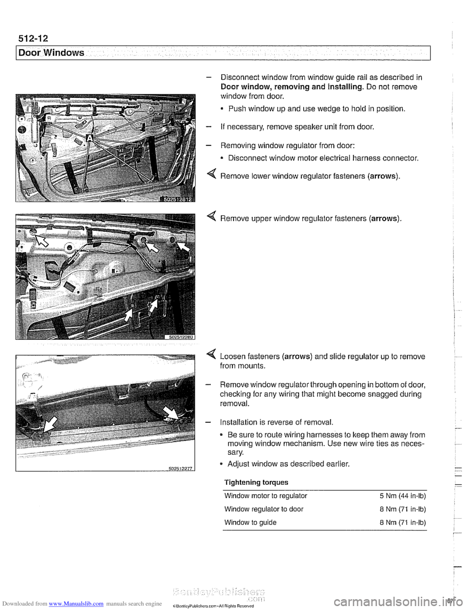
4 Remove lower window regulator fasteners (arrows).
Remove window regulator fasteners (arrows)
Loosen fasteners (arrows) and slide regulator up to remove
from mounts.
- Remove window regulatorthrough opening in bottom of door,
checking for any wiring that might become snagged during
removal.
- Installation is reverse of removal.
Be sure to route wiring harnesses to keep them away from
moving window mechanism. Use new wire ties as neces-
sary.
-
Tightening torques -
Window motor to regulator 5 Nm (44 in-lb)
502512211
Window regulator to door 8 Nm (71 in-lb)
Adjust window
as described earlier.
- -
W~ndow to guide 8 Nm (71 in-lb)
--
Page 877 of 1002
Downloaded from www.Manualslib.com manuals search engine
Door windows1
Rear window regulator, removing and
installing
NOTE-
BMW recommends removing the window regulator and mo-
tor as one unit, then separating the
two on the bench.
- Disconnect negative (-) cable from battery
- Remove door panel as described in 411 Doors
- Remove airbag unit and vapor barrier from door. See 721
Airbag System (SRS).
- Disconnect window from window guide rail as described in
Door window, removing and installing. Do not remove
window from door.
Push window up and use wedge to
hold in position.
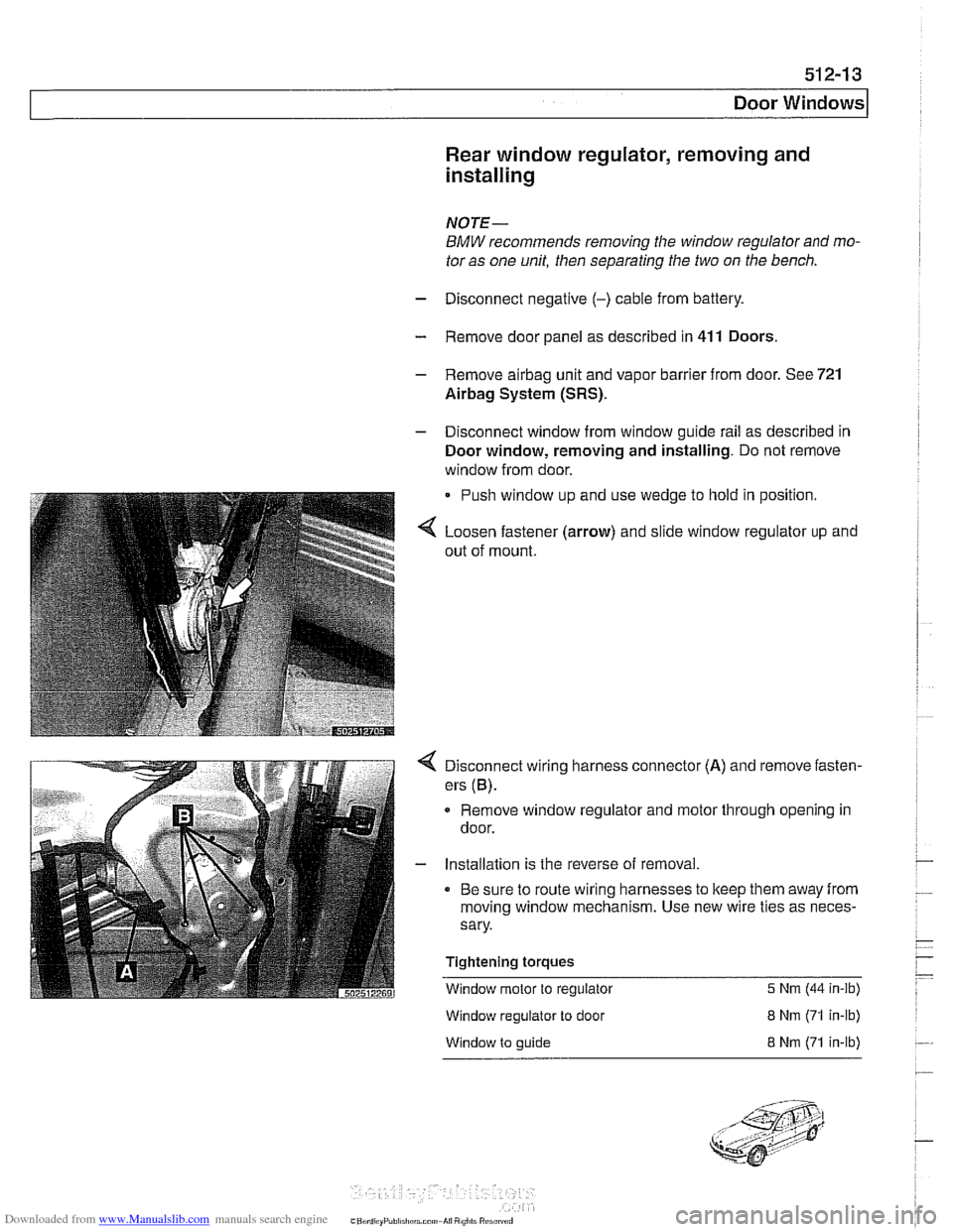
Loosen fastener (arrow) and slide window regulator up and
out of mount.
Disconnect wiring harness connector (A) and remove fasten-
ers
(6).
Remove window regulator and motor through opening in
door.
- Installation is the reverse of removal.
Be sure to route wiring harnesses to keep them away from
moving window mechanism. Use new wire ties as neces-
sary.
Tightening torques
Window motor to regulator
5 Nrn (44 in-ib)
Window regulator to door
Window to guide
8 Nrn (71 in-lb)
8 Nrn (71 in-lb)
Page 910 of 1002
Downloaded from www.Manualslib.com manuals search engine
51 5-1 6
Central Locking and Anti-Theft
DOOR HANDLES AND LOCKS
In the procedures that follow, door handle removal, door lock
cylinder removal and door latch removal are covered for the
left front door. Other doors are similar although simpler, due
to the
lack of lock cylinder.
Inside door release removal is covered in the procedure for
inner door
ane el removal. See 411 Doors.
Door handle (outer), removing and
installing
NOTE-
IfBMWspecial tools 51 3201 and51 3 203 are available, the
door handle can be removed without removing the door trim
panel or door
airbag. Use the access hole behind the rubber
sealing plug on the door edge.
- Close window on front door.
- Disconnect battery negative (-) cable.
CAUTlOG
Prior to disconnecting the batter)! read the battery discon-
nection cautions given
in 001 General Warnings and Cau-
tions.
Remove front door trim panel. See 411 Doors.
Remove door-mounted air bag. See 721
Airbag System
(SRS).
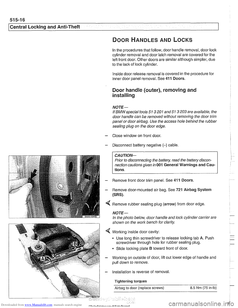
Remove rubber sealing plug (arrow) from door edge
NOTE-
In the photo below, door handle and lock cylinder carrier are
shown on the work bench for clarity.
Working inside door cavity:
- Use long thin screwdriver to release locking tab A. Push
screwdriver through hole for rubber sealing plug.
Slide locking plate
B toward front of door.
Working on outside of door, lift out lower edge of handle and
pull down to remove.
Installation is reverse of removal,
Tightening torques
Airbag to door (replace screws) 8.5 Nrn (75 in-lb)
Page 912 of 1002
Downloaded from www.Manualslib.com manuals search engine
51 5-1 8
I Central Locking and Anti-Theft
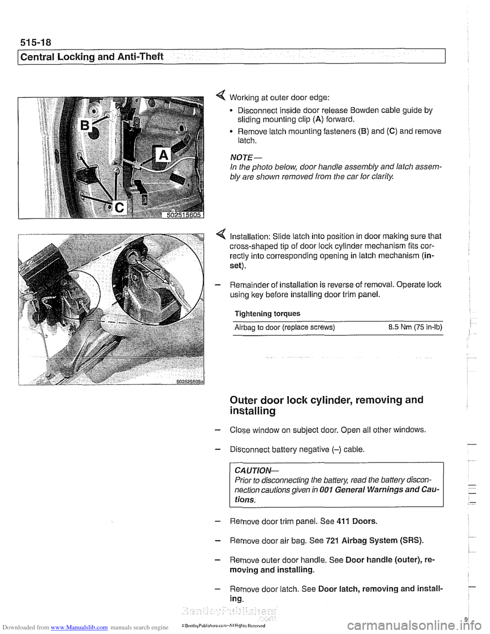
< Working at outer door edge:
Disconnect inside door release
Bowden cable guide by
sliding mounting clip (A) forward.
Remove latch mounting fasteners
(B) and (C) and remove
latch.
NOTE-
In the photo below, door handle assembly and latch assem-
bly are shown removed from the car
for clarity.
Installation: Slide latch into position in door making sure that
cross-shaped tip of door
loclc cylinder mechanism fits cor-
rectly into corresponding opening in latch mechanism (in-
set).
Remainder of installation is reverse of removal. Operate
loclc
using key before installing door trim panel.
Tightening torques
Airbag to door (replace screws) 8.5 Nm (75 in-lb)
Outer door lock cylinder, removing and
installing
- Close window on subject door. Open all other windows
- Disconnect battery negative (-) cable.
CA UTIOIG
Prior to disconnecting the baffeg read the battery discon-
nection cautions given in
001 General Warnings and Cau-
tions.
- Remove door trim panel. See 411 Doors.
- Remove door air bag. See 721 Airbag System (SRS).
- Remove outer door handle. See Door handle (outer), re-
moving and installing.
- Remove door latch. See Door latch, removing and install-
ing.
Page 913 of 1002
Downloaded from www.Manualslib.com manuals search engine
Central Locking and Anti-Theft
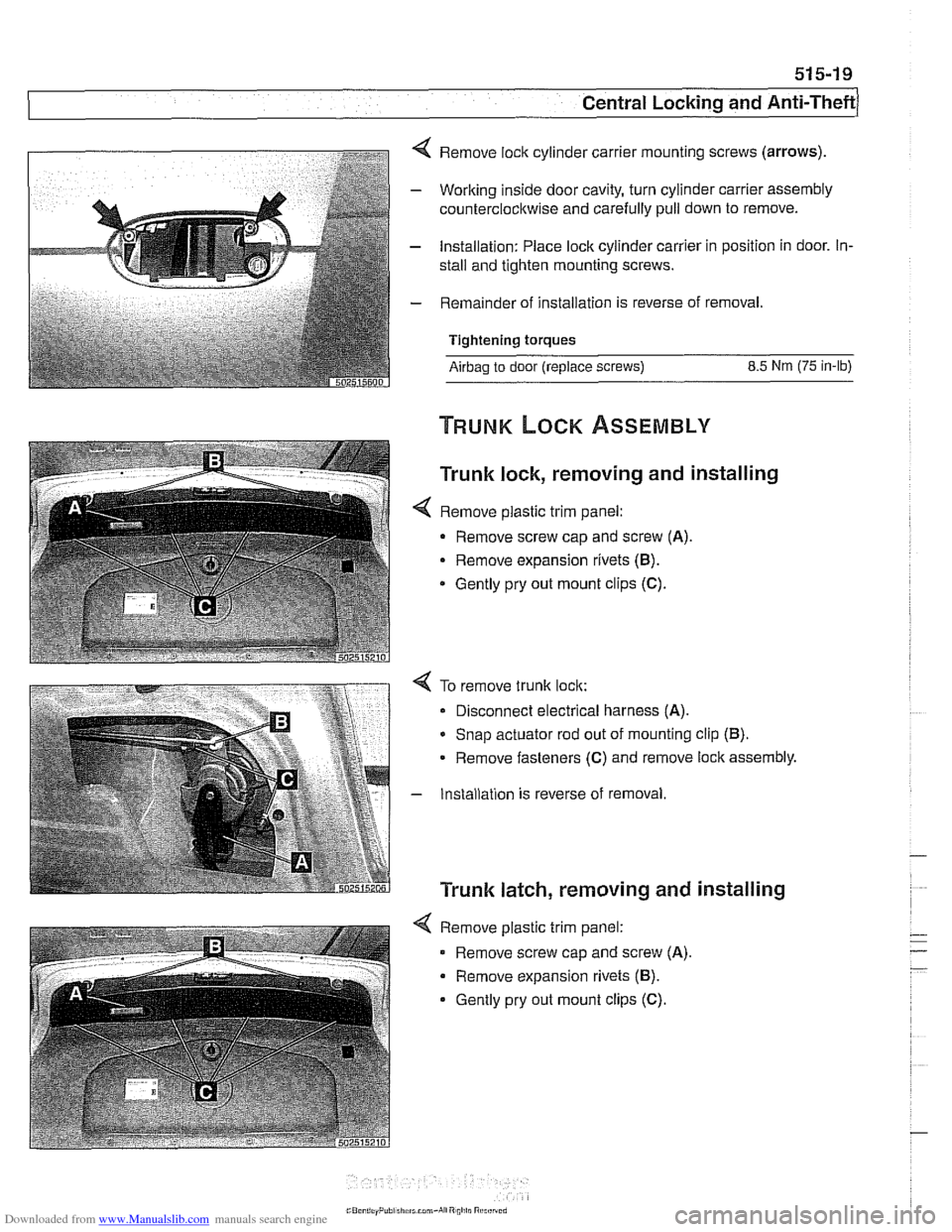
4 Remove lock cylinder carrier mounting screws (arrows).
- Working inside door cavity, turn cylinder carrier assembly
counterclockwise and carefully pull down to remove.
- Installation: Place lock cylinder carrier in position in door. In-
stall and tighten mounting screws.
- Remainder of installation is reverse of removal.
Tightening torques
Airbag to door (replace screws) 8.5 Nm (75 in-lb)
Trunk lock, removing and installing
< Remove plastic trim panel:
- Remove screw cap and screw (A).
Remove expansion rivets (B).
* Gently pry out mount clips (C).
4 To remove trunk lock:
Disconnect electrical harness
(A).
* Snap actuator rod out of mounting clip (B).
Remove fasteners (C) and remove lock assembly.
- Installation is reverse of removal
Trunk latch, removing and installing
4 Remove plastic trim panel:
Remove screw cap and screw
(A).
Remove expansion rivets (B).
Gently pry out mount clips (C).
Page 927 of 1002
Downloaded from www.Manualslib.com manuals search engine
Seats
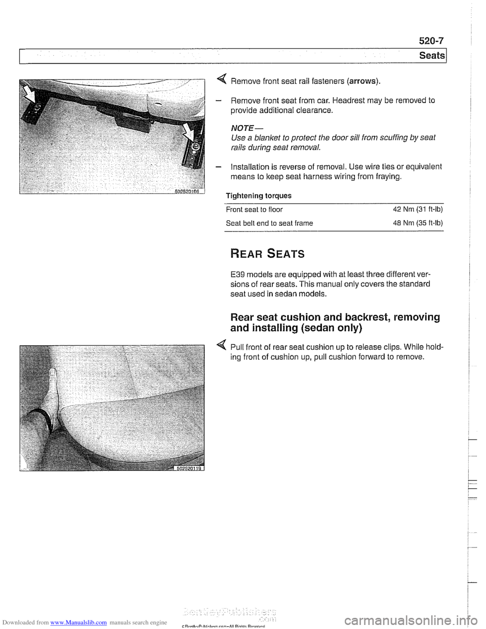
< Remove front seat rail fasteners (arrows)
- Remove front seat from car. Headrest may be removed to
provide additional clearance.
NOTE-
Use a blanket to protect the door sill from scuffing by seat
rails
during seat removal.
- Installation is reverse of removal. Use wire ties or equivalent
means to keep seat harness wiring from fraying.
Tightening torques
Front seat to floor
42 Nm (31 ft-lb)
Seat belt end to seat frame
48 Nm (35 ft-lb)
E39 models are equipped with at least three different ver-
sions of rear seats. This manual only covers the standard
seat used in sedan models.
Rear seat cushion and backrest, removing
and installing (sedan only)
4 Pull front of rear seat cushion up to release clips. While hold-
ing front of cushion up, pull cushion forward to remove.