Vanos BMW 540i 2000 E39 Owner's Manual
[x] Cancel search | Manufacturer: BMW, Model Year: 2000, Model line: 540i, Model: BMW 540i 2000 E39Pages: 1002
Page 148 of 1002
Downloaded from www.Manualslib.com manuals search engine
. ." ".
[Cylinder Head Removal and Installation - .. - -1 -
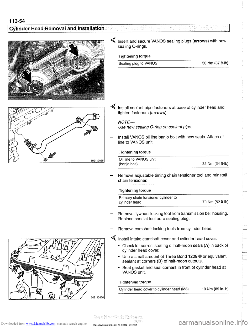
4 Insert and secure VANOS sealing plugs (arrows) with new
sealing O-rings.
Tightening torque Sealing
plug to VANOS 50
Nm (37 ft-lb)
4 Install coolant pipe fasteners at base of cylinder head and
tighten fasteners (arrows).
NOTE-
Use new sealing O-ring on coolant pipe.
- lnstall VANOS oil line banjo bolt with new seals. Attach oil
line to VANOS unit.
Tightening torque Oil line to VANOS unit
(banjo bolt) 32
Nm (24 ft-ib)
- Remove adjustable timing chain tensioner tool and reinstall
chain tensioner.
Tightening torque Primary chain tensioner cylinder to
cylinder head 70
Nm
(52 fi-ib)
- Remove flywheel locking tool from transmission bell housing.
Replace special tool bore sealing plug.
- Remove camshaft locking tools from cylinder head
4 lnstall intake camshaft cover and cylinder head cover.
0 Check for correct seating of half-moon seals (A) in back of
cylinder head cover.
Use a small amount of Three Bond
1209 8 or equivalent
sealant at corners
(B) of half-moon cutouts.
Seat gasket and seal corners in front of cylinder head at
VANOS unit.
Tightening torque
Cylinder head cover to cylinder head
(M6) 10 Nm (89 in-lb)
Page 150 of 1002
Downloaded from www.Manualslib.com manuals search engine
11 3-56
I Cvlinder Head Removal and Installation
- Installation of the remaining parts is reverse or removal, not-
ing the following:
- Refill cooling system as described in 170 Radiator and
Cooling System.
Change engine oil and filter as described in
020 Mainte-
nance.
If necessary, adjust accelerator cable.
a Reconnect battery.
CAUTION- To prevent damaging the engine electronic systems, installall
ground wire previously removed, including the ground wires
for the
ionition coils.
Tightening torque Coolant drain
pluq to cylinder bloclc 25 Nm (1 8 ft-lb)
Radiator cooling fan to coolant pump 40 Nm (30 ft-lb) -
Radiator drain screw to radiator 2.5
Nm (22 in-lb)
spark plug to cylinder head 25
Nm (1 8 ft-lb)
CYLINDER MEAD REMOVAL AND
INSTALLATION (M62 ENGINE)
This procedure covers cylinder head removal and installation
for the
M62 V-8 engine. Procedures forthe M62 TU VANOS
engine are not covered in this manual.
Intake manifold, left cylinder head, and right cylinder head re-
moval and installation are written as separate procedures.
The intake manifold must be removed before the cylinder
heads can be removed.
WARNING
-
Due to risk of personal injuv be sure the engine is cold be-
fore beginning the removal procedure.
Cylinder head removal and installation requires multiple spe-
cial service tools. Read the entire procedure before beginning
the repair.
Intake manifold, removal and installation,
M62 engine
- Disconnect negative (-) battery cable.
CAUTION- Prior to disconnecting the
batterj read the baitery discon-
nection cautions
in 001 General Cautions and Warnings.
Page 177 of 1002
Downloaded from www.Manualslib.com manuals search engine
11 6 Cylinder Head and Valvetrain
........................... General ............................ 1 16-2 Valves 116-56
.................... Special Tools ........................ 11 6-2 Valves. leak test 11 6-56
......... Valves. removing and installing 11 6-56 Cylinder Head ..................... .I1 6.5 ....................... Valve guides 11 6-57
Valves. leak test ...................... 11 6-6
Valve stem oil seals .................. 11 6-58 ...... ..""""."""ll 6.6 Valveseats ........................ 116-59 Hydraulic lifters, checking and replacing .. .I1 6-7 Valve ....................... 6-60 . .
Camshaft andLifter Removal
and Installation
.................... 11 6-1 1
Camshaft and lifter removal and
installation
(M52 engine) ............. .I1 6.12
Camshaft and lifter. removal and
installation (M52
TU and M54 engine) .... 11 6-1 9
Double VANOS timing chain components
. 11 6-28
Camshaft removal and installation
(M62 engine)
....................... 11 6-39
Page 178 of 1002
Downloaded from www.Manualslib.com manuals search engine
This group covers cylinder head and valvetrain service and
repair. Some of the repair procedures described here require
that the cylinder head first be removed as described in
113
Cylinder Head Removal and Installation.
NOTE- For timing chain and
VANOS repair information, see 117
Camshaft Timing Chain.
If it is
determined that the cylinder head will require signif-
icant reconditioning work, a remanufactured cylinder head
may be a good alternative. Remanufactured cylinder
heads are available from an authorized
BMW dealer.
The information given in this repair group is organized ac-
cording to engine code. For engine application information,
see
I00 Engine-General.
For specific repair procedures, refer to the appropriate repair
group:
* 020 Maintenance
100 Engine-General
113 Cylinder Head Removal and Installation
117 Camshafi Timing Chain
= 170 Radiator and Coo!ing System
Special Tools
Special BMW tools are required for most cylinder head ser-
vice described in this repair group. Many of these tools are ex-
pensive and only available through an authorized
BMW
dealer. If the special tools are not available, have the cylinder
head removed and disassembled by an authorized BMW
dealer. Be sure to read each procedure thoroughly before
starting a job to determine which special tools and equipment
will be necessary.
Most of the repairs to a cylinder head require precision
rna-
chine work to specific tolerances. This type of work should be
performed by an authorized BMW repairfacility or an ASE
certified machinist.
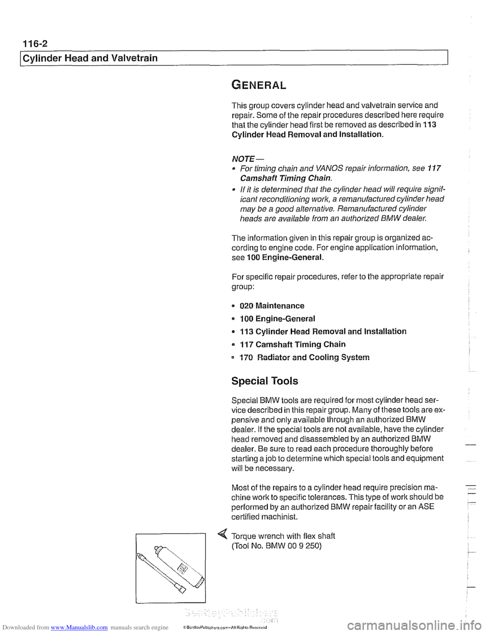
71 Torque wrench with flex shaft
Page 180 of 1002
Downloaded from www.Manualslib.com manuals search engine
/cylinder Head and Valvetrain
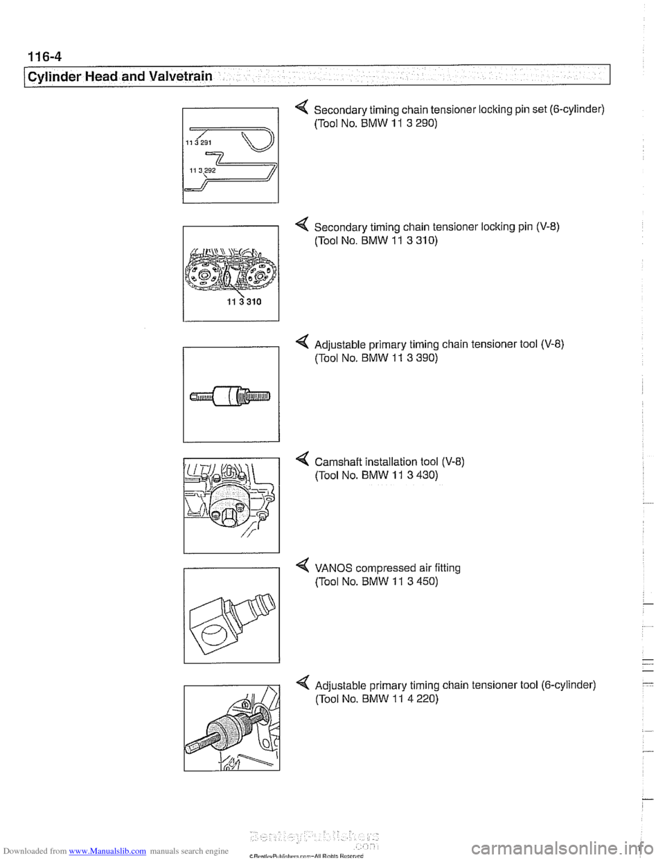
Secondary timing chain tensioner locking pin set (6-cylinder)
- 4 Secondary timing chain tensioner locking pin (V-8)
(Tool No. BMW
11 3 310)
4 Adjustable primary timing chain tensioner tool (V-8)
(Tool No. BMW
11 3 390)
4 Camshaft installation tool (V-8)
(Tool No.
BMW 11 3 430)
4 VANOS compressed air fitting
7 (Tool No. BMW 11 3 450)
Adjustable primary timing chain tensioner tool (6-cylinder) (Tool No. BMW
11 4 220)
Page 187 of 1002
Downloaded from www.Manualslib.com manuals search engine
Cylinder Head and Valvetrain
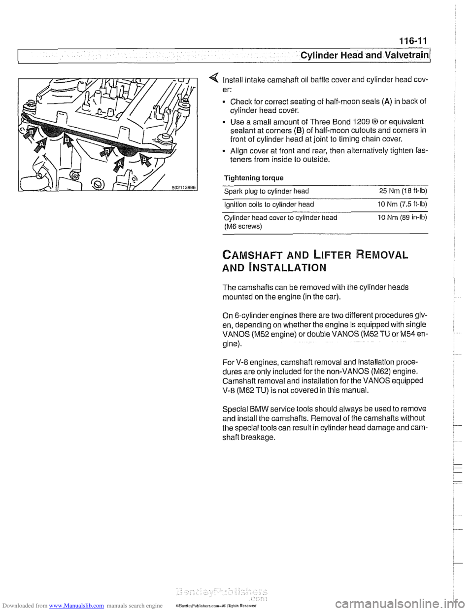
4 Install intake camshaft oil baffle cover and cylinder head cov-
er:
= Checlc for correct seating of half-moon seals (A) in back of
cylinder head cover.
Use a small amount of Three Bond 1209
@or equivalent
sealant at corners
(B) of half-moon cutouts and corners in
front of cylinder head at joint to timing chain cover.
Align cover at front and rear, then alternatively tighten fas-
teners from inside to outside.
Tightening torque
Sparic plug to cylinder head 25 Nm (18 it-lb)
Ignition coils to cylinder head 10 Nrn (7.5 ft-lb)
Cylinder head cover to cylinder iiead 10 Nrn (89 in-lb)
fM6 screws)
CAMSHAFT AND LIFTER REMOVAL
AND ~NSTALLATION
The camshafts can be removed with the cylinder heads
mounted on the engine (in the car).
On 6-cylinder engines there are two different procedures giv-
en, depending on whether the engine is equipped with single
VANOS (M52 engine) or double VANOS
(M52TU or M54 en-
gine).
For V-8 engines, camshaft removal and installation proce-
dures are
only included for the non-VANOS (M62) engine.
Camshaft removal and installation for the
VANOS eq;ipped
V-8 (M62TU) is not covered in this manual.
Special BMW service tools should always be used to remove
and install the camshafts. Removal of the camshafts without
the special tools can result in cylinder head damage and cam-
shaft breakage.
Page 188 of 1002
Downloaded from www.Manualslib.com manuals search engine
116-12
I Cylinder Head and Valvetrain
Camshaft and lifter removal and installation
(M52 engine)
Camshafts and lifters, removing (M52 engine)
WARNING
-
The process of evenly loosening the camshaft bearing cap
nuts is NOT an acceptable method of removing the cam-
shafts. Special tools should always be used to remove the
camshafts. Be sure to read the procedure
tlirough before
starting a job.
I Allow engine to cool before beginning this procedure. /
- Disconnect negative (-) cable from battery.
CAUTION-
Prior to disconnecting the batfew read the battery discon-
nection cautions given in
001 General Cautions and
Warnings.
- Remove VANOS control unit from cylinder head. See 117
Camshaft Timing Chain.
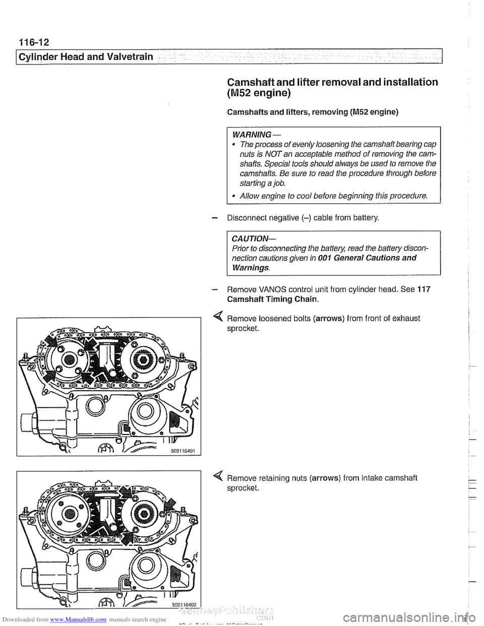
I I 4 Remove loosened bolts (arrows) from front of exhaust
sprocket
nuts
(arrows) from intake camshaft
Page 191 of 1002
Downloaded from www.Manualslib.com manuals search engine
116-15
Cylinder Head and Valvetrain
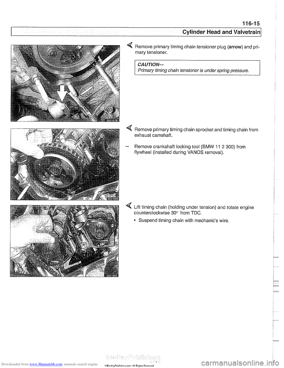
4 Remove primary timing chain tensioner plug (arrow) and pri-
mary tensioner.
CAUTION-
Primary timinq chain tensioner is under sarina aressure.
4 Remove primary timing chain sprocket and timing chain from
exhaust camshaft.
- Remove crankshaft locking tool (BMW 11 2 300) from
flywheel (installed during
VANOS removal).
Lift timing chain (holding under tension) and rotate engine
counterclockwise 30" from
TDC.
- Suspend timing chain with mechanic's wire
Page 195 of 1002
Downloaded from www.Manualslib.com manuals search engine
Cylinder Head and valvetrain1
- Remainder of installation is reverse of removal, noting the
following:
See
117 Camshaft Timing Chain for VANOS control unit
installation.
Tightening torques
Camshaft bearing caps
to cylinder head (M7) 15 Nm (1 1 ft-lb)
Cylinder head cover to cylinder head (M6) 10 Nm (89 in-lb)
Sparic plugs (M12) 23 Nm (17 ft-lb)
Camshaft and lifter, removal and
installation
(M52 TU and M54 engine)
Camshafts and lifters, removing
(M52 TU and M54 engine)
WARNING-
Allow engine fo cool before beginning this procedure.
- Disconnect negative (-) cable from battery.
CAUTION--
Prior to disconnecting the battea read the battery discon-
nection cautions in
001 General Cautions and Warnings.
Remove VANOS control unit. See 117 Camshaii Timing
Chain.
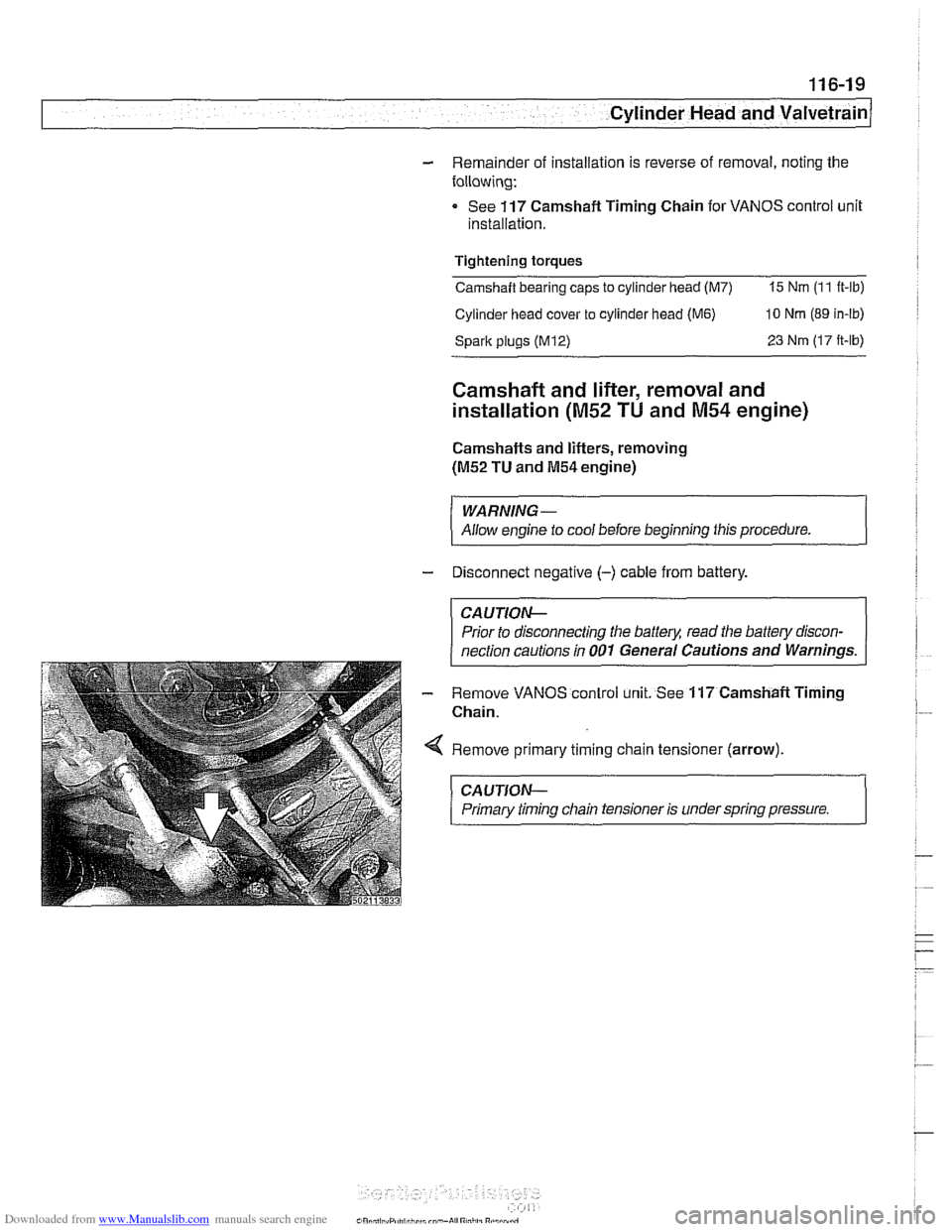
Remove primary timing chain tensioner (arrow).
CAUTION-
Primary timing chain tensioner is under spring pressure. 1
Page 204 of 1002
Downloaded from www.Manualslib.com manuals search engine
11 6-28
Cylinder Head and Valvetrain
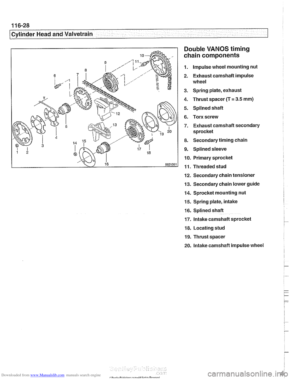
Double
VANOS timing
chain components
1. Impulse wheel mounting nut
2. Exhaust camshaft impulse
wheel
3. Spring plate, exhaust
4. Thrust spacer (T
= 3.5 mm)
5. Splined shaft
6. Torx screw
7. Exhaust camshaft secondary
sprocket
8. Secondary timing chain
9. Splined sleeve
10. Primary sprocket
11. Threaded stud
12. Secondary chain tensioner
13. Secondary chain lower guide
14. Sprocket mounting nut
15. Spring plate, intake
16. Splined shaft
17. Intake camshaft sprocket
18. Locating stud
19. Thrust spacer
20. lntake camshaft impulse wheel