Belts BMW 540i 2000 E39 Workshop Manual
[x] Cancel search | Manufacturer: BMW, Model Year: 2000, Model line: 540i, Model: BMW 540i 2000 E39Pages: 1002
Page 3 of 1002
Downloaded from www.Manualslib.com manuals search engine
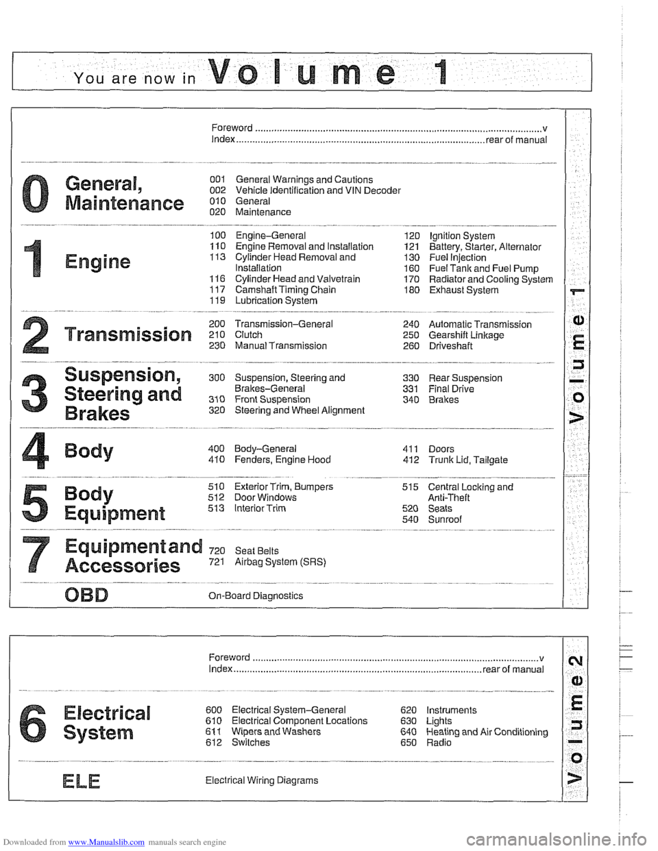
YOU are now in Volume I
I
Foreword ................... .. ........................................................................\
.......... v
Index
........................ .. ................................................................ rear of manual
General, 001 General Warnings and Cautions 002 Vehicle Identification and VIN Decoder
Maintenance OiO 020 Maintenance
Engine
100 Engine-General 110 Engine Removal and Installation
113 Cylinder Head Removal and
Installation
116 Cyiinder Head and Valvetrain 117 Camshaft Timing Chain
119 Lubrication System
200 Transmission-General
2 Transmission 210 clutch 230 ManualTransmission
I20 Ignition System
121 Battery, Starter, Alternator
130 Fuel Injection
160 Fuel Tank and Fuel Pump 170 Radiator and Cooling System
180 Exhaust System
240 Automatic Transmission
250 Gearshift Linkage 260 Driveshaft
Suspension, 300 Suspension, Steering and 330 Rear Suspension
Brakes-General 331 Final Drive
Steering and No Front Suspension 340 Brakes
320 Steering and Wheel Alignment
400 Body-General
410 Fenders, Engine Hood 411 Doors
412 Trunk Lid, Tailgate
510 Exterior Trim, Bumpers 512 Door Windows
Equipment 513 Interior Trim
7
Equipment and 720 seat Belts
Accessories 721 Airbag System (SRS)
OBD On-Board Diagnostics
. ............ ..
515 Central Lociting and
Anti-Theft
520 Seats 540 Sunroof
.................................................................... Foreword .............................. .. v
Index ................... .. ................................................................ rear of manual
Electrical
6 system
600 Electrical System-General 620 Instruments
610 Electrical Comoonent Locations 630 Liohts
611 wipers and washers 612 Switches eati in^ and Air Conditioning
Radio
. ........... ........ .........................
Electrical Wiring Diagrams
Page 9 of 1002
Downloaded from www.Manualslib.com manuals search engine
002 Vehicie identification and
VlN Decoder
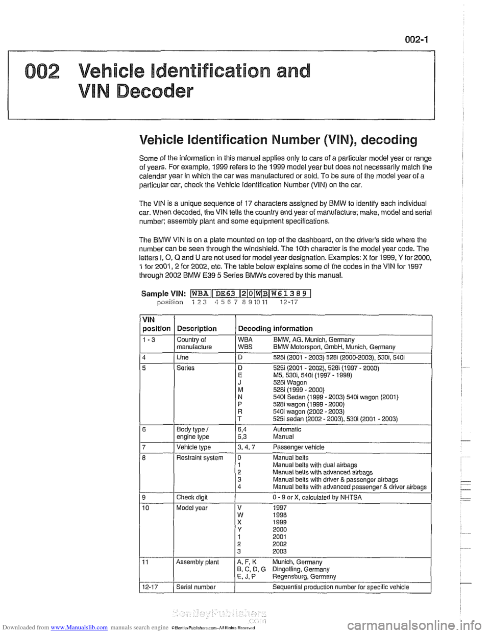
Vehicle identification Number (VIN), decoding
Some of the information in this manual applies only to cars of a parlicuiar model year or range
of vears. For
examole. 1999 refers to the 1999 model vear but does not necessarilv malch the
caiendsr year in which the car was manufactured or sold. To be sure of the model year of a
particular car,
checic the Vehicle ldentification Number (VIN) on the car.
The VIN is a unique sequence of 17 characters assigned by BMW lo identify each individual
car. When decoded, the VIN tells the country and year of manufacture; make, model and serial
number: assembly
plant and some equipment specifications.
The BMW VIN is on a plate mounted on top of the dashboard, on the driver's side where the
number can be seen through the windshield, The 10th character is the model year code. The
letters
I. 0, Q and U are not used for model year designation. Examples: X for 1999, Y for 2000,
1 for 2001,2 for 2002, etc. The table below explains some of the codes in the VIN for 1997
through 2002 BMW
E39 5 Series BMWs covered by this manual.
Sample
VIN: ~~Iz~o~w~B~w~ 13 8 9 1 lposition 1 2 3 zi 5 6 7 8 9 10 11 12-17
VIN
position Description Decoding information
1-3 Countrv of WBA B
I J 1 znan~+q ;BT BMW Molorsporl. Gmon, ~;nch Gerrn;!n,
Linc 525 (2UU1 - 2003) 528 (2000-2003. 530; 540 i
5
1
Manual belts with dual airbags Manual belts with advanced airbaos
Series
Body
type
i engine lype . ..
D 5251 (2001 - 2002), 528i (1997 - 2000) E MS. 530i, 540i (1997 - 1998) J 5251 Wagon
M 528i (1999 - 2000) N 5401 Sedan (1999 - 2003) 540i wagon (2001)
P 528i wagon (1999 - 2000) R 540i waaon 12002 - 20031
6,4 Aulomatic 5,3 Manual
Vehicle type 3.4.7 Passenger vehicle
Checlr digit
Model year Restraint
system
1 0 Manual belts
3 Manual belts wilh driver
& passenger airbags 4
Manual belts with advanced passenger B driver airbags
0 - 9 or X, calculated by NHTSA
V 1997 W 1RRR
Assembly plant A, F, K Munich, Germany
B, C, D, G Dingolfing. Germany E, J. P Reqensburq. Germany .
Serial number
Sequential produclion number lor specific vehicle
Page 14 of 1002
Downloaded from www.Manualslib.com manuals search engine
.
General
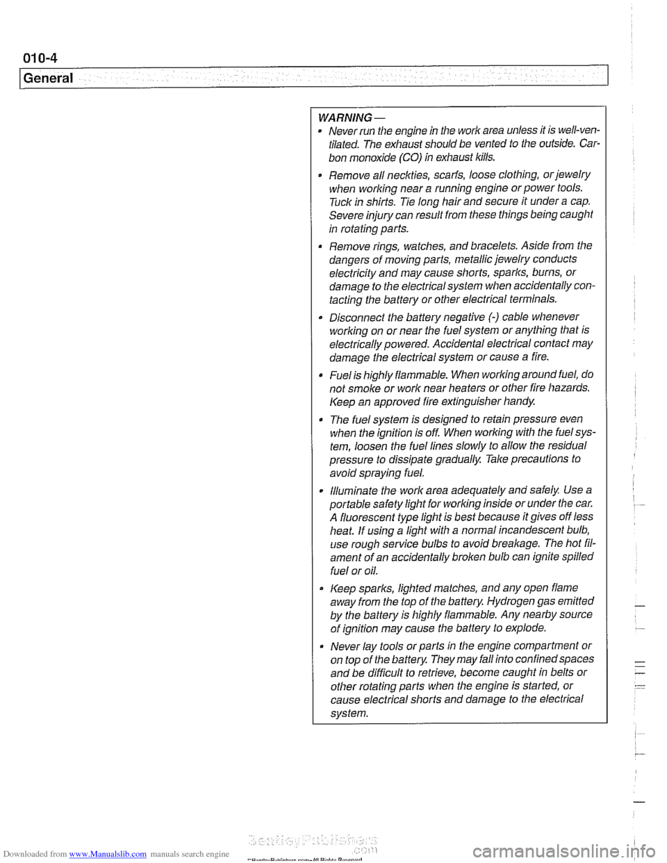
WARNING-
Never run the engine in tile work area unless it is well-ven-
tilated. The exhaust should be vented to the outside. Car-
bon monoxide (CO) in exhaust kills.
Remove all neckties,
scarfs, loose clothing, or jewelry
when working near a running engine or power tools.
Tuck in shirts. Tie long hair and secure it under a cap.
Severe injury can result from these things being
caugiit
in rotating parts.
Remove rings, watches, and bracelets. Aside from the
dangers of moving parts, metallic jewelry conducts
electricity and may cause shorts, sparks, burns, or
damage to the electricalsystem when accidentally con-
tacting the battery or other electrical terminals.
Disconnect the battery negative
(-) cable whenever
working on or near the fuel system or anything that is
electrically powered. Accidental electrical contact may
damage the electrical system or cause a fire.
Fuelis highly flammable. When working around fuel, do
not
smoke or work near heaters or other fire hazards.
Keep an approved fire extinguisher handy.
The fuel system is designed to retain pressure even
when the ignition is off When worlcing with the
fuelsys-
tem, loosen the fuel lines slowly to allow the residual
pressure to dissipate gradually. Take precautions to
avoid spraying fuel.
. Illuminate the worlc area adequately and safely Use a
portable safety light for worlcing inside or under the car.
A fluorescent type
light is best because it gives off less
heat. If using a light with a normal incandescent bulb,
use rough service bulbs to avoid
breakage. The hot fil-
ament of an accidentally broken bulb can ignite spilled
fuel or oil.
Keep sparks, lighted matches, and any open flame
away from the top of the battery. Hydrogen gas
emitted
by the battery is highly flammable. Any nearby source
of ignition may cause the battery to explode.
Never lay
tools or parts in the engine compartment or
on top of the battery. They may
fallinto confinedspaces
and be difficult to retrieve, become caught in belts or
other rotating parts when the engine is started, or
cause electrical shorts and damage to the electrical
system.
Page 33 of 1002
Downloaded from www.Manualslib.com manuals search engine
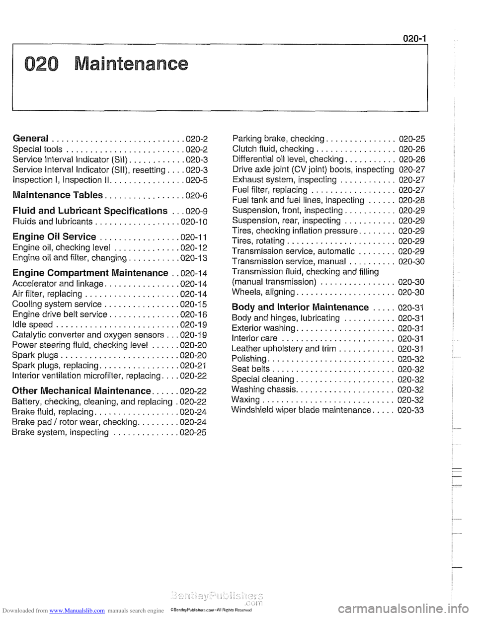
020 Maintenance
General ........................... .02 0.2
Special tools ........................ .02 0.2
Service Interval Indicator (Sll) ........... .02 0.3
Service Interval Indicator (Sll), resetting ... .02 0.3
Inspection I, Inspection 11 ............... .02 0.5
Maintenance Tables ................ .02 0.6
Fluid and Lubricant Specifications .. .02 0.9
Fluids and lubricants ................. .02 0.10
Engine Oil Service ................ .02 0.1 I
Engine oil. checking level ............. .02 0.12
Engine oil and filter. changing .......... .02 0-13
Engine Compartment Maintenance . .02 0.14
Accelerator and linkage ............... .02 0.14
Air filter. replacing ................... .02 0.1 4
Cooling system service ............... .02 0.15
Engine drive belt service .............. .02 0.16
Idlespeed .......................... 020-19
Catalytic converter and oxygen sensors .. .02 0.19
Power steering fluid, checking level ..... .02 0.20
Spark plugs ........................ .02 0.20
Spark plugs, replacing ................ .02 0.21
Interior ventilation microfilter, replacing ... .02 0.22
Other Mechanical Maintenance ..... .02 0.22
Battery, checking. cleaning. and replacing .02 0-22
Brake fluid. replacing ................. .02 0-24
Brake pad 1 rotor wear. checking ........ .02 0.24
Brake system, inspecting ............. .02 0.25
Parking brake. checking ............... 020-25
Clutch fluid. checking ................. 020-26
Differential oil level. checking ........... 020-26
Drive axle joint (CV joint) boots. inspecting 020-27
Exhaust system. inspecting ............ 020-27
Fuel filter. replacing .................. 020-27
Fuel tank and fuel lines. inspecting ...... 020-28
Suspension. front. inspecting ........... 020-29
Suspension. rear. inspecting ........... 020-29
Tires. checking inflation pressure ........ 020-29
Tires. rotating ....................... 020-29
Transmission service. automatic ........ 020-29
Transmission service. manual .......... 020-30
Transmission fluid. checking and filling
(manual transmission)
................ 020-30
Wheels. aligning ..................... 020-30
Body and Interior Maintenance ..... 020-31
Body and hinges. lubricating ........... 020-31
Exterior washing ..................... 020-31
Interior care ........................ 020-31
Leather upholstery and trim ............ 020-31
Polishing ........................... 020-32
Seat belts .......................... 020-32
Special cleaning ..................... 020-32
Washing chassis ..................... 020-32
Waxing ............................ 020-32
Windshield wiper blade maintenance ..... 020-33
Page 48 of 1002
Downloaded from www.Manualslib.com manuals search engine
020-1 6
Maintenance
loose, hose is damaged, or connection is dirty or corroded.
Dried coolant has achalky appearance. Hoses should be firm
and springy. Replace any hose that is cracked, has become
soft and limp, or has been contaminated by oil.
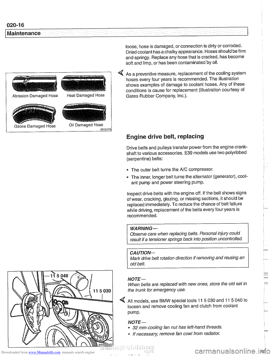
4 As a preventive measure, replacement of the cooling system
hoses every four years is recommended. The illustration
shows examples of damage to coolant hoses. Any of these
conditions is cause for replacement (illustration courtesy of
/ Abrasion Damaged Hose Heat Damaged Hose 1 Gates Rubber Company, I~c.).
Engine drive belt, replacing
Drive belts and pulleys transfer power from the engine crank-
shaft to various accessories.
E39 models use two polyribbed
(serpentine) belts:
The outer belt turns the
NC compressor.
0 The inner, longer belt turns the alternator (generator), cool-
ant pump and power steering pump.
Inspect drive belts with the engine off. If the belt shows signs
of wear, cracking, glazing, or missing sections, it should be
replaced
immediately. To reduce the chance of belt failure
while driving, replacement of the belts every four years is
recommended.
WARNING -
Observe care when replacing belts. Personal injury could
result if a tensioner springs back into position uncontrolled.
CA UTIOI\C
Mark drive belt rotation direction if removing and reusing an
old belt.
NOTE-
When belts are replaced with new ones, store the old set in
the trunk for emergency use.
All models, use
BMW special tools 11 5 030 and 11 5 040 to
loosen and remove cooling fan and clutch from coolant
pump.
NOTE-
32 mm cooling fan nut has left-hand threads
If necessary, remove fan cowl from radiator.
Page 64 of 1002
Downloaded from www.Manualslib.com manuals search engine
020-32
Maintenance
using a soft cloth. Regular use of a good quality leather condi-
tioner will reduce drying and cracking of the leather.
Polishing
Use paint polish only if the finish assumes a dull loolc afler
long service. Polish can be used to remove tar spots and tar-
nish, but
afleiwards a coat of waxshould be applied to protect
the clean finish. Do not use abrasive polish or cleaners on
aluminum trim or accessories.
Seat belts
Dirt and other abrasive particles will damage seat belt web-
bing. If it is necessary to clean seat belts, use a mild soap so-
lution. Bleach and other strong cleaning agents may weaken
the belt webbing and should be avoided.
WARNING-
Do not clean the seat belt webbing using dry cleaning or oth-
er chemicals. Allow wet belts to
dry before allowing them to
retract.
-
The condition of the belt webbing and the function of the re-
tractor mechanisms should be inspected. See
720 Seat Belts
for seat belt inspection information.
Speciai cieaning
Tarspots can be removed with a bug and tar remover. Never
use gasoline,
lterosene, nail polish remover, or other unsuit-
able solvents. Insect spots also respond to tar remover.
A bit
of baking soda dissolved in the wash water will facilitate their
removal. This method can also be used to remove tree sap
spots.
Washing chassis
Periodic washing of the underside of the car, especially in
winter, will help prevent accumulation of road salt and rust.
The best time to wash the underside is just afler the car has
been driven in wet conditions. Spray the chassis with a pow-
erful jet of water. Commercial or self-service carwashes may
not be bestforthis, as they may recycle the salt-contaminated
water.
Waxing
For a long-lasting, protective, and glossy finish, apply a hard
wax after the car has been washed and dried. Use carnauba
or synthetic based products. Waxing is not needed after
every washing. You can tell when waxing is required by
look-
Page 85 of 1002
Downloaded from www.Manualslib.com manuals search engine
Engine Removal and Installation
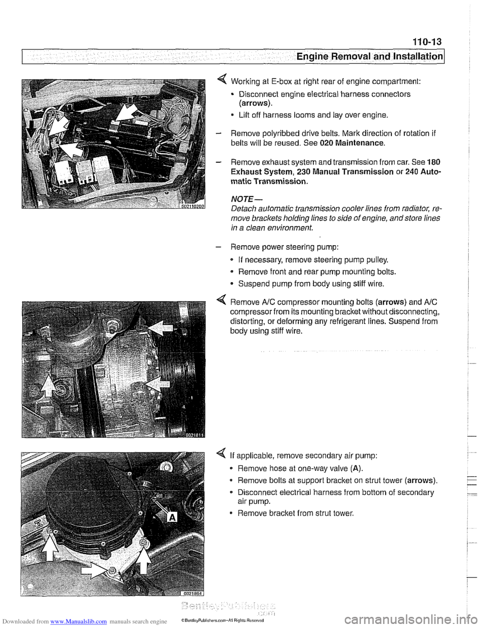
4 Working at E-box at right rear of engine compartment:
Disconnect engine electrical harness connectors
(arrows).
Lift off harness looms and lay over engine.
- Remove polyribbed drive belts. Mark direction of rotation if
belts will be reused. See 020 Maintenance.
- Remove exhaust system and transmission from car. See 180
Exhaust System, 230 Manual Transmission or 240 Auto-
matic Transmission.
NOJE-
Detach automatic transmission cooler lines from radiator, re-
move brackets holding lines to side of engine, andstore lines
in a clean environment.
- Remove power steering pump:
If necessary, remove steering pump pulley.
Remove front and rear pump mounting bolts.
Suspend pump from body using stiff wire.
4 Remove A/C compressor mounting bolts (arrows) and AIC
compressor from its mounting bracketwithoutdisconnecting,
distorting, or deforming any refrigerant lines. Suspend from
body using stiff wire.
4 If applicable, remove secondary air pump:
Remove hose at one-way valve
(A).
Remove bolts at support bracket on strut tower (arrows).
- Disconnect electrical harness from bottom of secondary
air pump.
Remove bracket from strut tower.
Page 87 of 1002
Downloaded from www.Manualslib.com manuals search engine
110-15
Engine Removal and lnstallation
- Installation is reverse of removal, noting the following:
Replace all gaskets. O-rings and seals.
Use new fuel injector seals
Check that engine drive belts properly engage pulley
grooves.
Inspect O-ring seal between mass air flow sensor and air
filter housing. To facilitate reassembly, coat seal with acid-
free grease.
Change engine oil and filter and
check all other fluid levels.
See
020 Maintenance.
Refill and bleed cooling system. See
170 Radiator and
Cooling System.
CAUTION--
When reattaching throttle assembly harness connectoc con-
nector is
fuNy tightened when arrows on connector and plug
line up.
Tightening torques
Coolant drain plug to cylinder block
25 Nm (18 ft-lb)
Engine mount to
subframe (M10) 45 Nm (33 ft-ib)
Exhaust manifold to cylinder head
M6 10 Nm (89 in-lb)
M7 or ME 20 Nm (15 ft-lb)
Intake manifold to cylinder head
M7 15 Nm (I 1 ft-lb)
ME 22 Nm (16 ft-lb)
Radiator cooling fan to coolant pump
40 Nm (30 ft-lb)
Radiator drain screw to radiator
2.5 Nm (22 in-lb)
Page 93 of 1002
Downloaded from www.Manualslib.com manuals search engine
--
-- Engine Removal and installation' -
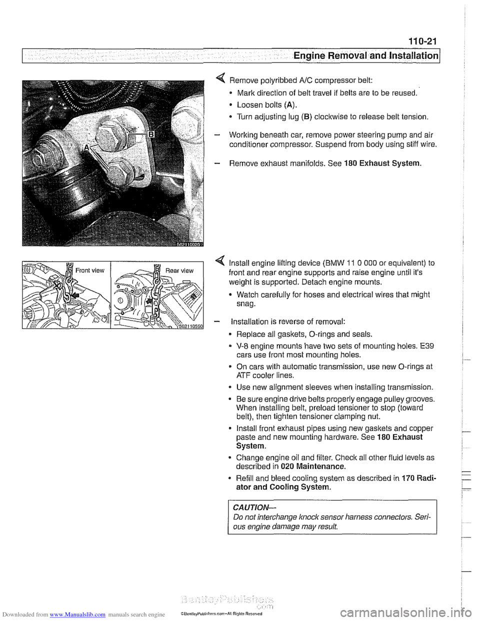
Remove polyribbed A/C compressor belt:
Mark direction of belt travel if belts are to be reused.
Loosen bolts
(A).
Turn adjusting lug (B) clocltwise to release belt tension.
Working beneath car, remove power steering pump and air
conditioner compressor. Suspend from body using stiff wire.
Remove exhaust manifolds. See
180 Exhaust System.
< lnstall engine lifting device (BMW 11 0 000 or equivalent) to
front and rear engine supports and raise engine until it's
weight is supported. Detach engine mounts.
a Watch carefully for hoses and electrical wires that might
snag.
- installation is reverse of removal:
Replace all gaskets, O-rings and seals.
V-8 engine mounts have two sets of mounting holes. E39
cars use front most mounting holes.
* On cars with automatic transmission, use new O-rings at
ATF cooler lines.
Use new alignment sleeves when installing transmission.
Be sure engine drive belts properly engage pulley grooves.
When installing belt, preload tensioner to stop (toward
belt), then tighten tensioner clamping nut.
lnstall front exhaust pipes using new gasltets and copper
paste and new mounting hardware. See
180 Exhaust
System.
Change engine oil and filter. Check all other fluid levels as
described in
020 Maintenance.
Refill and bleed cooling system as described in
170 Radi-
ator and Cooling System.
CAUTION-
Do not interchange knoclc sensor harness connectors. Seri-
ous engine damage may result
Page 124 of 1002
Downloaded from www.Manualslib.com manuals search engine
Cylinder Head Removal and installation - - .- - - - -
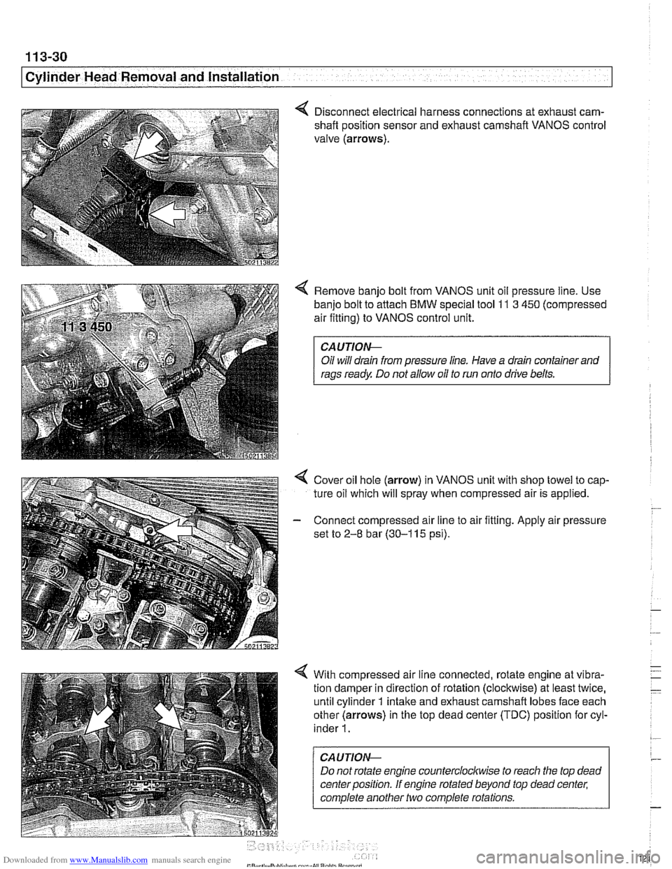
4 Disconnect electrical harness connections at exhaust cam-
shaft position sensor and exhaust camshaft VANOS control
valve (arrows).
4 Remove banjo bolt from VANOS unit oil pressure line. Use
banjo bolt to attach
BMW special tool 11 3 450 (compressed
air fitting) to VANOS control unit.
CAUTIOI\C
Oil will drain from pressure line. Have a drain container and
rags ready Do not allow oil to run onto drive belts.
4 Cover oil hole (arrow) in VANOS unit with shop towel to cap-
ture oil which will spray when compressed air is applied.
- Connect compressed air line to air fitting. Apply air pressure
set to
2-8 bar (30-1 15 psi).
4 With compressed air line connected, rotate engine at vibra-
tion damper in direction of rotation (clockwise) at least twice,
until cylinder 1 intake and exhaust camshaft lobes face each
other (arrows) in the top dead center (TDC) position for cyl-
inder
1.
CAUTION--
Do not rotate engine counterclocltwise to reach the top dead
center position. If engine rotated beyond top dead center;
complete another two complete rotations.