coolant level BMW 540i 2000 E39 Workshop Manual
[x] Cancel search | Manufacturer: BMW, Model Year: 2000, Model line: 540i, Model: BMW 540i 2000 E39Pages: 1002
Page 39 of 1002
Downloaded from www.Manualslib.com manuals search engine
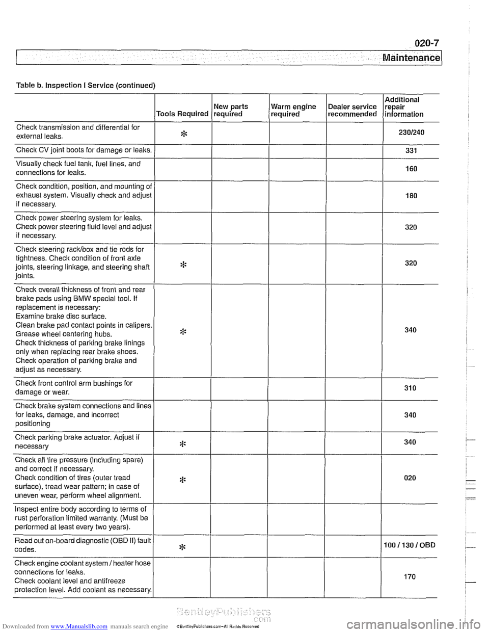
Table b. Inspection I Service (continued)
Checlt transmission and differential for
external lealts.
Check CV joint boots for damage or leaks.
Visually
check fuel tank, fuel lines, and
connections for
leaks.
New parts
Tools Required required
Check condition, position, and mounting
ol
exhaust system. Visually check and adjusl
if necessary.
Check power steering system for lealts.
Check power steering
fluid level and adjust
if necessary.
Check steering racidbox and tie rods for
tightness. Checit condition of front axle
joints, steering
linkage, and steering shaft
joints.
Check overall thickness of front and rear
bralte pads using
BMW special tool. If
replacement is necessary:
Examine brake disc surface.
Clean brake pad contact points in calipers
Grease wheel centering hubs.
Checlt thickness of parking brake linings
only when replacing rear brake shoes.
Checit operation of pariting brake and
adjust as necessary.
Checlt front control arm bushings for
damage or wear.
Check brake system connections and
lines
for leaks, damage, and incorrect
positioning Warm
engine
(~ealer service Irepair , required recommended lnformat~on
Check parking braite actuator. Adjust if
necessary
Check ail tire pressure (including spare)
and correct if necessary.
Checlt condition of tires (outer tread
surface), tread wear pattern: in case of
uneven wear, perform wheel alignment.
inspect entire body according to terms of
rust oerforation limited warrantv. (Must be
*:
4:
2 ~ perfdrmed at least every two years). I
Read out on-board diagnostic (OBD 11) fault
codes.
Checkengine coolant
system1 heater hose
connections for
leaks.
Checit coolant level and antifreeze
protection level. Add coolant as necessary.
* 100113010BD
I
170
Page 43 of 1002
Downloaded from www.Manualslib.com manuals search engine
020-1 1
Maintenance
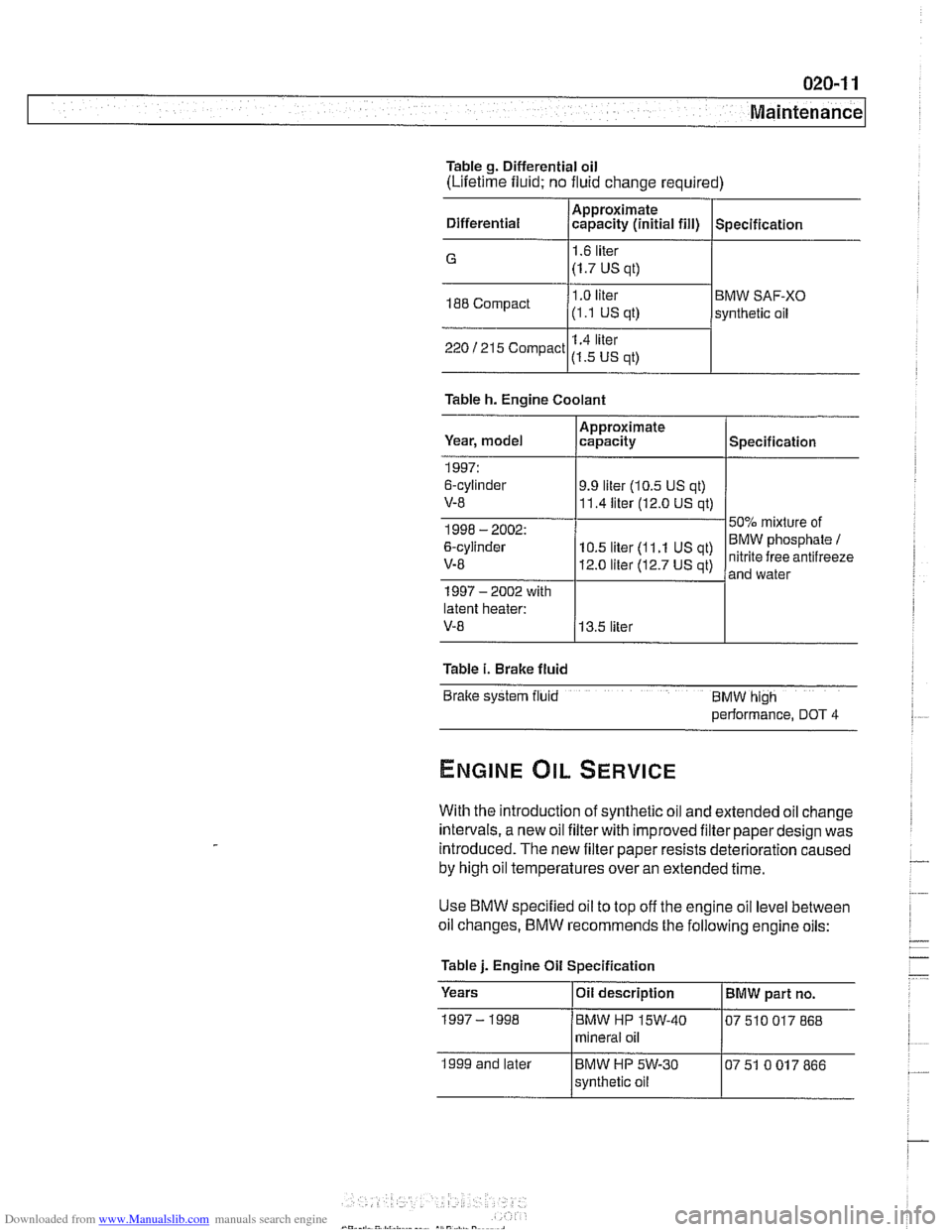
Table g. Differential oil
(Lifetime fluid; no fluid change required)
Differential
/Approximate. capaclty (in~t~al fill) I Spec~f~cat~on , , .
G 1.6 liter
(1.7 US
at) I
188 Compact I .O liter BMW SAF-XO
(1 .I US ql) synthetic oil
1.4
liler 220 1215 Compact US qt) I
Table h. Engine Coolant
Year, model
latent heater:
V-8 13.5 liter
1997:
6-cylinder
V-8
Table
i. Brake fluid
Bralte system fiuld BMW hlgh
performance, DOT 4
Approximate
capacity
9.9 liter (10.5 US qt)
11.4 liter (12.0 US qt)
With the introduction of synthetic oil and extended oil change
intervals, a new oil filterwith improved filter paper design was
introduced. The new filter paper resists deterioration caused
by high oil temperatures over an extended time.
Specification
Use BMW specified oil to top off the engine oil level between
oil changes.
BMW recommends the following engine oils:
Table
j. Engine Oil Specification
Years
IOii description I BMW part no.
1999 and later mineral
oil
BMW
HP 5W-30
svnthetic oil 07
51 0 017 866
Page 47 of 1002
Downloaded from www.Manualslib.com manuals search engine
Maintenance
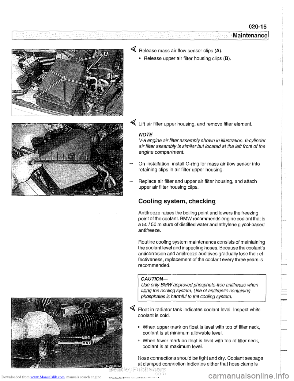
< Release mass air flow sensor clips (A).
Release upper air filter housing clips (B).
4 Lift air filter upper housing, and remove filter element.
NOTE-
V-8 engine air filter assembly shown in illustration. 6-cylinder
air filter assembly is similar but located at the left front of the
engine compartment.
- On installation, install O-ring for mass air flow sensor into
retaining clips in air filter upper housing.
- Replace air filter and upper air filter housing, and attach
upper air filter housing clips.
Cooling system, checking
Antifreeze raises the boiling point and lowers the freezing
~oint of the coolant. BMW recommends enaine coolantthat is
a 50 150 mixture of distilled water and ethGene glycol-based
antifreeze.
Routine cooling system maintenance consists of maintaining
the coolant level and inspecting hoses. Because the coolant's
anticorrosion and antifreeze additives gradually lose their ef-
fectiveness, replacement of the coolant every three years is
recommended.
CAUJION-
Use only BMWapprovedphosphate-free antifreeze when
filing the cooling system. Use of antifreeze containing
phosphates is harmful to the cooling system.
4 Float in radiator tank indicates coolant level. Inspect while
coolant is cold.
When upper mark on float is level with top of filler neck,
coolant is at minimum allowable level.
When lower mark on float is level with top of filler neck,
coolant is at maximum level.
Hose connections should be tight and dry. Coolant seepage
nnection indicates either that hose clamp is
Page 87 of 1002
Downloaded from www.Manualslib.com manuals search engine
110-15
Engine Removal and lnstallation
- Installation is reverse of removal, noting the following:
Replace all gaskets. O-rings and seals.
Use new fuel injector seals
Check that engine drive belts properly engage pulley
grooves.
Inspect O-ring seal between mass air flow sensor and air
filter housing. To facilitate reassembly, coat seal with acid-
free grease.
Change engine oil and filter and
check all other fluid levels.
See
020 Maintenance.
Refill and bleed cooling system. See
170 Radiator and
Cooling System.
CAUTION--
When reattaching throttle assembly harness connectoc con-
nector is
fuNy tightened when arrows on connector and plug
line up.
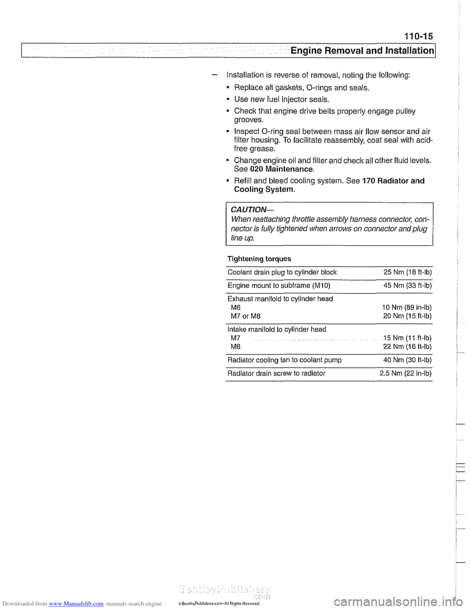
Tightening torques
Coolant drain plug to cylinder block
25 Nm (18 ft-lb)
Engine mount to
subframe (M10) 45 Nm (33 ft-ib)
Exhaust manifold to cylinder head
M6 10 Nm (89 in-lb)
M7 or ME 20 Nm (15 ft-lb)
Intake manifold to cylinder head
M7 15 Nm (I 1 ft-lb)
ME 22 Nm (16 ft-lb)
Radiator cooling fan to coolant pump
40 Nm (30 ft-lb)
Radiator drain screw to radiator
2.5 Nm (22 in-lb)
Page 92 of 1002
Downloaded from www.Manualslib.com manuals search engine
11 0-20
Engine Removal and Installation
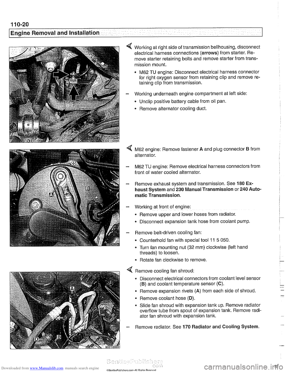
Working at right side of transmission bellhousing, disconnect
electrical harness connections (arrows) from starter. Re-
move starter retaining bolts and remove starter from trans-
mission mount.
M62 TU engine: Disconnect electrical harness connector
for right oxygen sensor from retaining clip and remove re-
taining clip from transmission.
- Working underneath engine compartment at left side:
Unclip positive battery cable from oil pan.
. Remove alternator cooling duct.
4 M62 engine: Remove fastener A and plug connector B from
alternator.
- M62 TU engine: Remove electrical harness connectors from
front of water cooled alternator.
- Remove exhaust system and transmission. See 180 Ex-
haust System and 230 Manual Transmission or 240 Auto-
matic Transmission.
- Working at front of engine:
Remove upper and lower hoses from radiator.
D~sconnect expansion tank hose from coolant pump.
- Remove belt-driven cooling fan:
Counterhold fan with special tool
11 5 050.
Turn fan mounting nut (32 mm) clockwise (left hand
threads) to loosen.
Rotate fan clockwise to remove.
Remove cooling fan shroud:
Disconnect electrical connectors from coolant level sensor
(B) and coolant temperature sensor (C).
. Remove expansion rivets (A) from each side of shroud
Remove coolant hose
(D).
Slide fan shroud with expansion tank up. Remove radiator
overflow tube from spout of expansion tank. Remove radi-
ator fan shroud with expansion tank.
Remove radiator. See
170 Radiator and Cooling System.
Page 433 of 1002
![BMW 540i 2000 E39 Workshop Manual Downloaded from www.Manualslib.com manuals search engine
130-43
Fuel Injection ]
I I I
12 llnput IFeedback signal, engine start /Starter
Table c. Siemens MS 42.0 and MS 43.0 ECM pin assignments BMW 540i 2000 E39 Workshop Manual Downloaded from www.Manualslib.com manuals search engine
130-43
Fuel Injection ]
I I I
12 llnput IFeedback signal, engine start /Starter
Table c. Siemens MS 42.0 and MS 43.0 ECM pin assignments](/img/1/2822/w960_2822-432.png)
Downloaded from www.Manualslib.com manuals search engine
130-43
Fuel Injection ]
I I I
12 llnput IFeedback signal, engine start /Starter
Table c. Siemens MS 42.0 and MS 43.0 ECM pin assignments (continued)
I I - I
13 Input /I Alternator (generator) Notes
Throttle
valve
Crankshaft position sensor
Throttle valve (MS
42.0)
Throttle valve
Pin
6
7
8
9
10
11
14
15
16
17
18
19
20
I 1- I
23 l~round I~round, intaite air temperature sensor /Intake air temperature sensor
Signal
Output
Input
Input
Input
I I I
Component/function
Not used
Throttle valve supply potentiometer
2
Signal, crankshaft position sensor
Signal,
pedal position sensor 2 (MS 42.0)
Signal, throttle position sensor 1
Not used
Ground
Ground
Input
Ground
Ground
Input
Ground Cranltshaft position sensor
21
24
25
26
27
28
29
30
I 1- I
33 1 input ISignal, cylinder 1 fuel injector /cylinder 1 fuel injector
Ground, throttle position sensor (MS
42.0)
Ground, exhaust camshaftsensor I
Signal, pedal position sensor 1 (MS 42.0)
Ground, mass air flow sensor
Ground, intake camshaft sensor
1
Signal, throttle potentiometer 1
Ground, throttle position sensor
22 loutput I~ignal, intake air temperature Ilntake air temperature sensor
I I - I
Throttle
valve (MS 42.0)
Camshaft position sensor I
Throttle valve (MS
42.0)
Hot film mass air flow sensor
Camshaft position sensor i
Throttle valve
Throttle valve
Ground
Output
Ground Input
Output
Ground
Output
Out~ut
Ground, crankshaft position sensor
Knoclt sensor
31
34
35
36
37
38
39
Signal, coolant temperature sensor
Ground, coolant temperature sensor
Signal,
oil pressure
Signal, engine
oil temperature sensor
Ground, engine oil temperature sensor
Signal, knock sensor
Signal, knock sensor
32 loutput ISignal, ltnock sensor l~nock sensor
40
41
Coolant temperature sensor
Coolant temperature sensor
Oil pressure switch
Oil temperature sensor
Oil temperature sensor
Knoclt sensor
I
Input
input
Input
Input
Input
Inout
Signal, knock sensor
Input
Input Signal, cylinder
2 fuel injector
Signal, cylinder
3 fuel injector
Signal, cylinder
4 fuel injector
Signal, cylinder
5 fuel injector
Signal, cylinder
6 fuel injector
Sianai, oil level sensor Cylinder
2 fuel
injector
Cylinder
3 fuel injector
Cylinder
4 fuel injector
Cylinder
5 fuel injector
Cylinder
6 fuel injector
Oil level sensor
-
Signal. VANOS inlet valve
Signal. VANOS outlet valve VANOS
inlet valve
VANOS outlet valve
Page 469 of 1002
Downloaded from www.Manualslib.com manuals search engine
Fuel Injection I
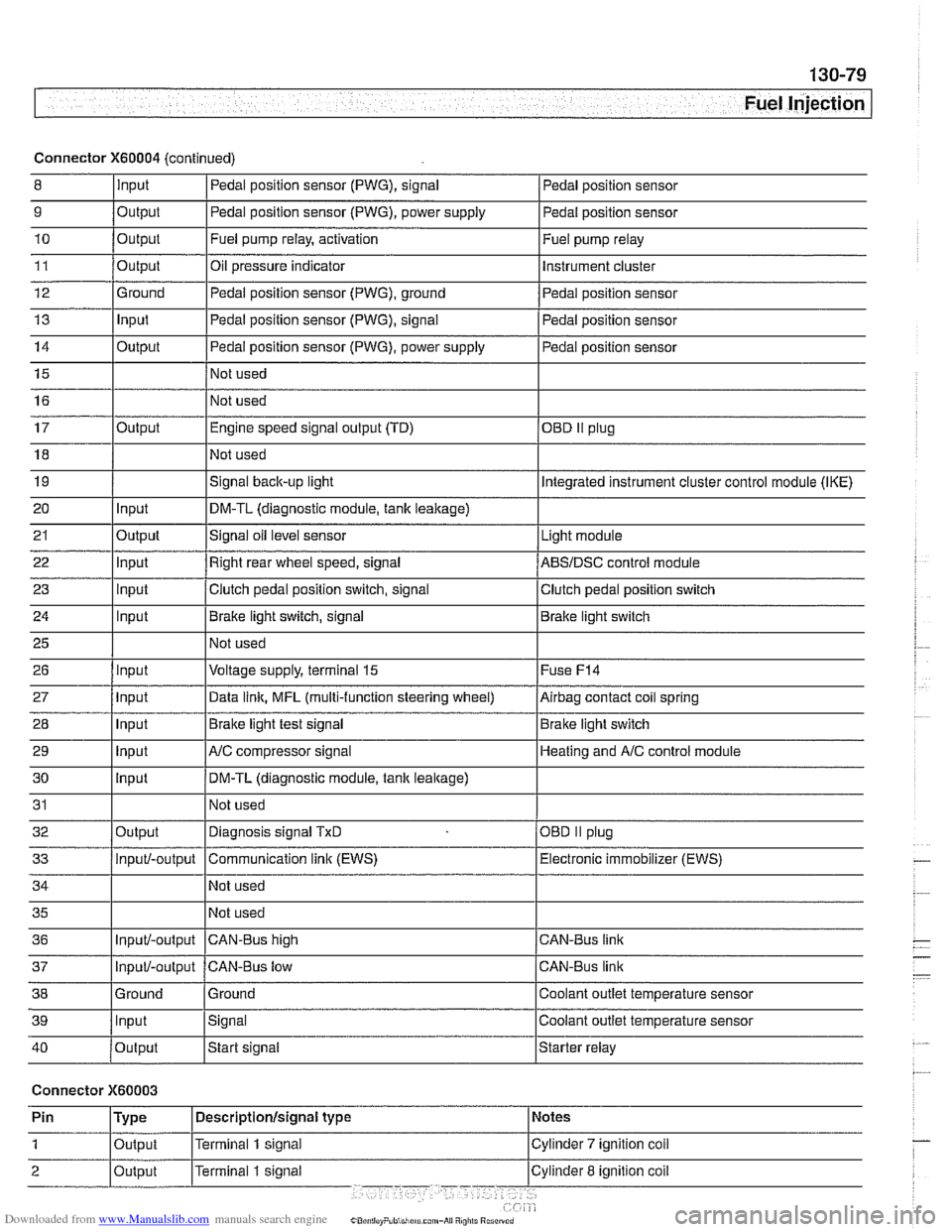
Connector X60004 (continued)
8 10
11
12
13
14
15
16
9
Output 0
Input
17
18
19
20
21
22
23
24
25
26
27
28
29
30
31
32
33
34
35
36
39
llnput lsignal l~oolant outlet temperature sensor
Output
Output
Ground
Input
Output
I I - I
40 /output Istart signal Istarter relay
Pedal position sensor (PWG), signal
Output Input
Output
input
Input
Input
Input
Input
Input
input
Input
Output
Input/-output
Input/-output
37
Connector X60003
Pedal position sensor
Fuel pump relay, activation
Oil pressure indicator Pedal position sensor (PWG), ground
Pedal position sensor (PWG), signal
Pedal position sensor (PWG), power supply
Not used
Not used Fuel
pump relay
Instrument cluster
Pedal position sensor
Pedal position sensor
Pedal position sensor
Engine speed signal output (TD)
Not used
Signal
back-up light
DM-TL (diagnostic module,
tank leakage)
Signal oil level sensor
Right rear wheel speed, signal
Clutch pedal position switch, signal
Brake light switch, signal
Not used
Voltage supply, terminal
15
Data link, MFL (multi-function steering wheel)
Brake light test signal
AJC compressor signal
DM-TL (diagnostic module, tank
leakage)
Not used
Diagnosis signal
TxD
Communication link (EWS)
Not used
Not used
CAN-BUS hiqh
38 1 Ground l~round I Coolant outlet temperature sensor
OED II plug
Integrated instrument cluster control module (IKE)
Light module
ABSIDSC control module
Clutch pedal position switch
Brake light switch
Fuse
F14
Airbag contact coil spring
Brake light switch
Heating and
A/C control module
OBD
II plug
Electronic immobilizer (EWS)
CAN-Bus link
CAN-Bus link
Input/-output CAN-Bus low
Page 500 of 1002
Downloaded from www.Manualslib.com manuals search engine
-
I Radiator and Cooling System
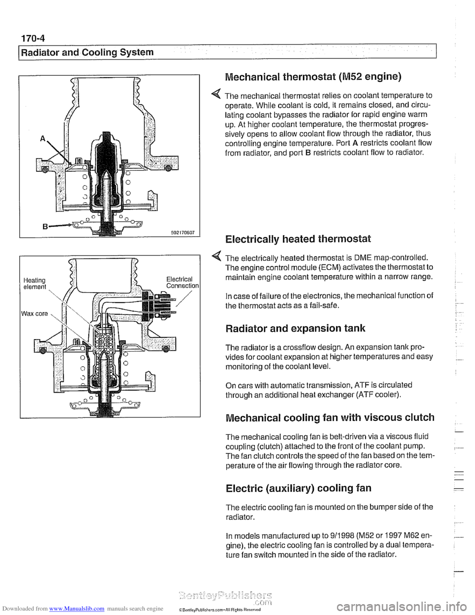
Mechanical thermostat
(M52 engine)
4 The mechanical thermostat relies on coolant temperature to
operate. While coolant is cold, it remains closed, and circu-
lating coolant bypasses the radiator for rapid engine warm
up. At higher coolant temperature, the thermostat progres-
sively opens to allow coolant flow through the radiator, thus
controlling engine temperature. Port
A restricts coolant flow
from radiator, and port
B restricts coolant flow to radiator.
Electrically heated thermostat
4 The electrically heated thermostat is DME map-controlled.
The engine control module (ECM) activates the thermostat to
maintain engine coolant temperature within a narrow range.
In case of failure of the electronics, the mechanical function of
the thermostat acts as a fail-safe.
Radiator and expansion tank
The radiator is a crossflow design. An expansion tank pro-
vides for coolant expansion at higher temperatures and easy
monitoring of the coolant level.
On cars with automatic transmission, ATF is circulated
through an additional heat exchanger (ATF cooler).
Mechanical cooling fan with viscous clutch
The mechanical cooling fan is belt-driven via a viscous fluid
coupling (clutch) attached to the front of the coolant pump.
The fan clutch controls the speed of the fan based on the tem-
perature of the air flowing through the radiator core.
Electric (auxiliary) cooling fan
The electric cooling fan is mounted on the bumper side of the
radiator.
In models manufactured up to
911 998 (M52 or 1997 M62 en-
gine), the electric cooling fan is controlled by a dual tempera-
ture fan switch mounted in the side of the radiator.
Page 504 of 1002
Downloaded from www.Manualslib.com manuals search engine
170-8
I Radiator and Cooling System
Common cooling system faults can be grouped into one of 4
categories:
Cooling system
lealts
Poor coolant circulation
Radiator cooling fan faults
Electrical/electronic faults
Cooling system inspection
- Check that coolant pump drive belt tensioner is functioning
properly and that belt tension is correct. Belt tensioner sys-
tems for the different models are shown in
020 Maintenance.
- Check condition of coolant pump drive belt.
- Checlc coolant hoses for cracks or softness. Checlc clamps
for looseness. Check coolant level and check for evidence of
coolant
lealts from engine.
- Check that radiator fins are not blocked with dirt or debris.
Clean radiator using low-pressure water or compressed air.
Blow outward, from engine side out.
- To check coolant pump:
Remove mechanical cooling fan. See Mechanical
(vis.
cous clutch) cooling fan, removing and installing.
Remove drive belt from coolant pump pulley. See
020
Maintenance.
Firmly grasp opposite sides of pulley and check for play in
all directions.
Spin pulley and check that shaft runs smoothly without
play.
NOTE-
The coolant provides lubrication for the pump shaft, so an oc-
casional drop of coolant
lealing from the pump is acceptable.
If coolant drips steadily from the vent hole, replace the pump.
- At normal engine operating temperature, cooling system is
pressurized. This raises boiling point of coolant.
Leaks may
prevent system from becoming pressurized. If visual evi-
dence is inconclusive, pressure test cooling system as de-
scribed later to help pinpoint hard-to-find leaks.
- If cooling system is full of coolant and holds pressure:
- Use an appropriate scan tool to interrogate engine control
module (ECM) for radiator fan or DME control circuit faults.
Checlc for loose or worn drive belt.
0 Test for failed thermostat or coolant pump impeller. Some
pumps may be fitted with plastic impellers.
Page 510 of 1002
Downloaded from www.Manualslib.com manuals search engine
Radiator and Cooling System
Cooling system, bleeding
Trapped air in the cooling system can prevent proper coolant
circulation and overheating. Wheneverthe coolant is drained
and filled, bleed the cooling system to remove trapped air.
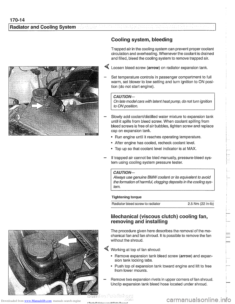
4 Loosen bleed screw (arrow) on radiator expansion tank.
- Set temperature controls in passenger compartment to full
warm, set blower to low setting and turn ignition to
ON posi-
tion (do not start engine).
CAUTIOIG
On late model cars with latent heat pump, do not turn ignition
to ON position.
- Slowly add coolanUdistilled water mixture to expansion tank
until it spills from bleed screw. When coolant spilling from
bleed screws is free of air bubbles, tighten screw and replace
cap on expansion tank.
Run engine until it reaches operating temperature,
- After engine has cooled, recheck coolant level.
Top up so that coolant level indicator is at MAX.
- If trapped air cannot be bled manually, pressure-bleed sys-
tem using cooling system pressure tester.
CA UTlON--
Always use genuine BMW coolant or its equivalent to avoid
the formation of harmful, clogging deposits
in the cooling sys-
tem.
Tightening torque
Radiator bleed screw to radiator 2.5 Nm (22 in-lb)
Mechanical (viscous clutch) cooling fan,
removing and installing
The procedure given here describes the removal of the me-
chanical fan and fan shroud. It is possible to remove the fan
without the shroud.
< Working at top of fan shroud:
Remove expansion tank bleed screw (arrow) and expan-
sion tank locking tabs.
Push top of expansion
tank toward engine and lift to free
from lower mounts.
- Remove two expansion rivets in upper corners of fan shroud.
Unclip expansion tank bleed hose located under shroud.