glove box BMW 540i 2000 E39 Workshop Manual
[x] Cancel search | Manufacturer: BMW, Model Year: 2000, Model line: 540i, Model: BMW 540i 2000 E39Pages: 1002
Page 40 of 1002

Downloaded from www.Manualslib.com manuals search engine
--- -
Maintenance
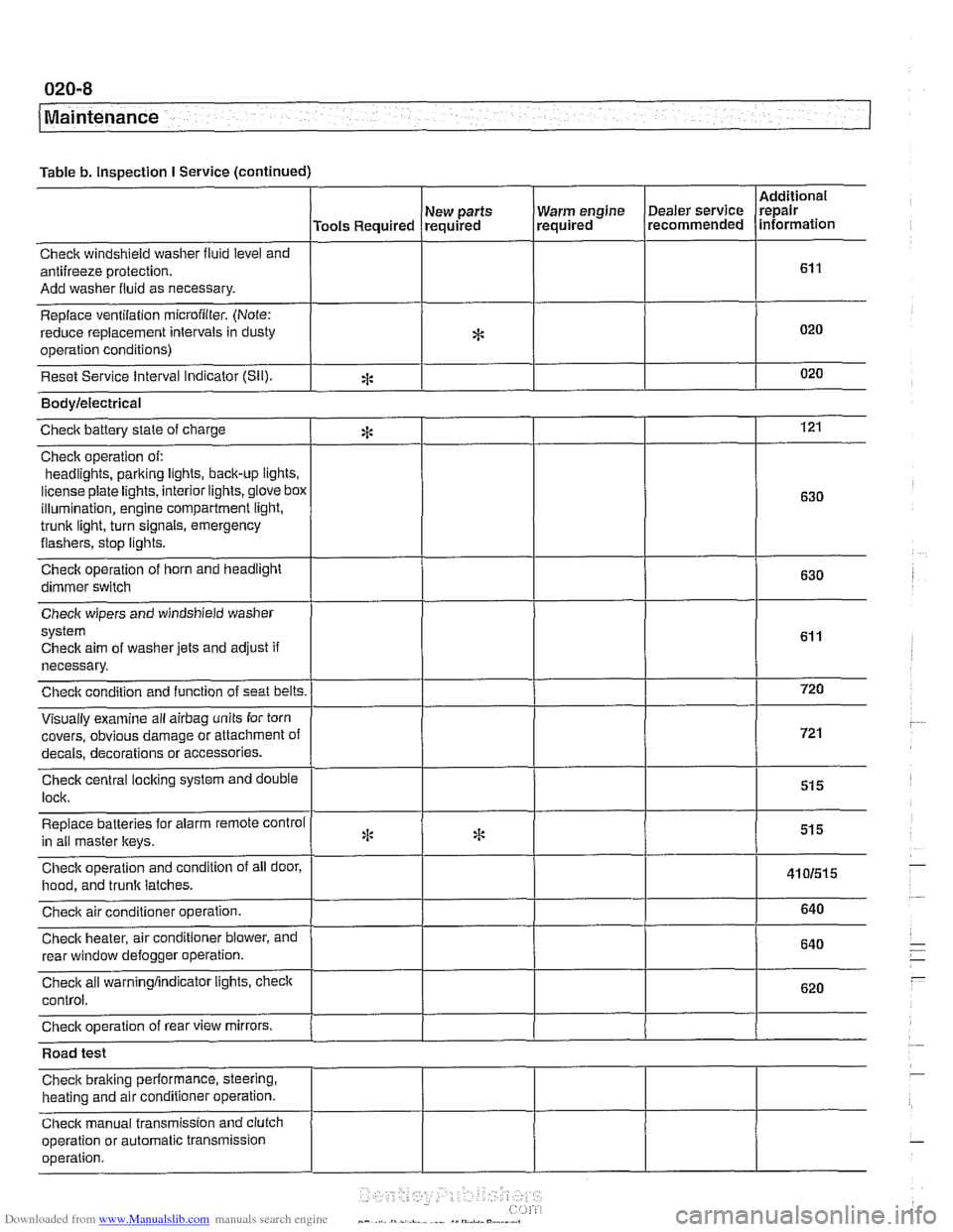
Table b. Inspection I Service (continued)
I I I I
Warm engine Dealer service
required recommended
Check windshield
washer fluid level and
antifreeze protection.
Add washer fluid as necessary.
Replace ventilation
microfilter. (Note:
reduce replacement intervals in dusty
operation conditions)
Reset Service interval Indicator
(Sil).
Additional
repair
information
Tools Required
*
eck aim of washer jets and adjust if
necessary.
covers, obvious damage or attachment o
s or accessories.
Road test
Check braking performance, steering,
heating and air conditioner operation.
Check manual transmission and clutch
operation or automatic transmission
operation. New
parts
required
*
Bodylelectrical
121
630
630
Checic battery state of charge
Check operation of:
headlights,
parking iights, back-up lights.
license plate lights, interior lights,
glove box
illumination, engine compartment light,
trunk light, turn signals, emergency
flashers, stop iights.
Check operation of horn and headlight
dimmer switch
:i:
Page 462 of 1002

Downloaded from www.Manualslib.com manuals search engine
130-72
Fuel Injection
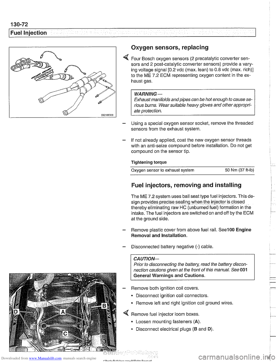
I Oxygen sensors, replacing
4 Four Bosch oxygen sensors (2 precatalytic converter sen-
sors and
2 post-catalytic converter sensors) provide a vary-
ing voltage signal
[0.2 vdc (max. lean) to 0.8 vdc (max. rich)]
to the ME
7.2 ECM representing oxygen content in the ex-
haust gas.
WARNING-
Exhaust manifolds and pipes can be hot enough to cause se-
rious burns. Wear suitable heavy gloves and other appropri-
ate protection.
- Using a special oxygen sensor socltet, remove the threaded
sensors from the exhaust system.
- If not already applied, coat the new oxygen sensor threads
with an anti-seize compound before installation. Do not get
compound on the sensor tip.
Tightening torque
Oxygen sensor to exhaust system
50 Nm (37 ft-lb)
Fuel injectors, removing and installing
The ME 7.2 system uses ball seat type fuel injectors. This de-
sign
prov:des precise seal'ng when the iniector is closed
therebv eiminalinq raw HC (unb~rned fue ) formalion in tne
intake.-~he fuel inkctors areswitched on and off by the ECM
at the ground side.
- Remove plastic cover from above fuel rail. See100 Engine
Removal and Installation.
- Disconnected battery negative (-) cable.
CAUTION-
Prior to disconnecting the battea read the battery discon-
nection cautions given at the front of this manual. See 001
General Warnings and Cautions.
- Remove both ignition coil covers.
Disconnect ignition coil connectors.
Remove left and right ignition coil ground wires,
4 Remove fuel injector loom boxes.
Loosen mounting fasteners
(A).
Disconnect electrical plugs (B and D).
Page 882 of 1002

Downloaded from www.Manualslib.com manuals search engine
51 3-4
/Interior Trim
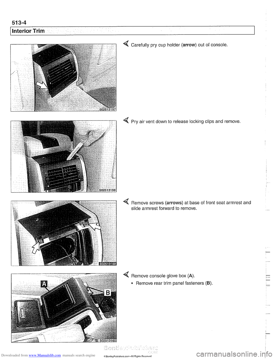
Carefully pry cup holder (arrow) out of console,
4 Pry air vent down to release locking clips and remove.
< Remove screws (arrows) at base of front seat armrest and
slide armrest forward to remove.
4 Remove console glove box (A).
Remove rear trim panel fasteners (B).