immobilizer BMW 540i 2000 E39 Workshop Manual
[x] Cancel search | Manufacturer: BMW, Model Year: 2000, Model line: 540i, Model: BMW 540i 2000 E39Pages: 1002
Page 369 of 1002
Downloaded from www.Manualslib.com manuals search engine
Battery, Starter, ~lternatorl
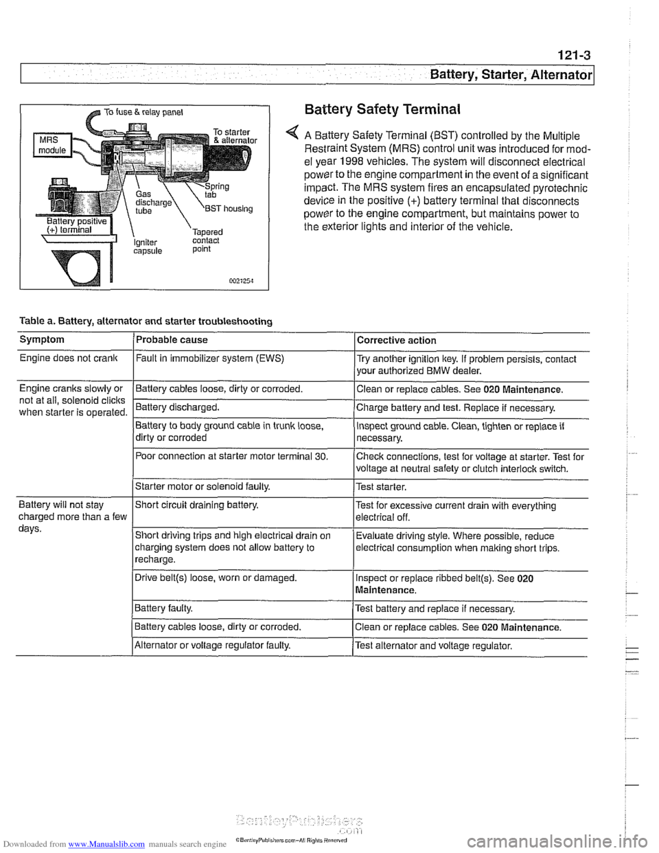
@ TO fuse & relay panel Battery Safety Terminal
A Battery Safety Terminal (BST) controlled by the Multiple
Restraint System (MRS) control unit was introduced for mod-
el year 1998
vehicles. The system will disconnect electrical
power to the engine compartment
in the event of a significant
impact. The MRS system fires an encapsulated pyrotechnic
device
in the positive (+) battery terminal that disconnects
power to the engine compartment, but maintains power to
the exterior lights and interior of the vehicle.
point
002125~1
Table a. Battery, alternator and starter troubleshooting
1-
/Starter motor or solenoid faulty. l~est starter.
Symptom
Engine does not crank
Engine cranks slowly or
not at all, solenoid
clicits
when starter is operated.
I I
Battery will not stay IShort circuit draining battery. l~est for excessive current drain with everything
Probable cause
Fault
in immobilizer system (EWS)
-Clean Battery cables loose, dirty or corroded.
Battery discharged.
Battery to body ground cable in trunk
loose,
dirty or corroded
Poor connection at starter motor terminal
30.
Corrective action
Try another ignition key. If problem persists, contact
your authorized BMW dealer.
or replace cables. See 020
~aintenance.
Charge battery and test. Replace if necessary.
inspect ground cable. Clean, tighten or replace if
necessary.
Checlc connections, test for voltage at starter. Test for
voltage at neutral safety or clutch
interloclc switch.
charged more than a few
days.
I~atter~ faulty. /Test battery and replace if necessary.
Short driving trips and high electrical drain
on
charging system does not allow battery to
recharge.
. I
I Battery cables loose, dirty or corroded. Iclean or replace cables. See 020 Maintenance.
Evaluate driving
style. Where possible, reduce
electrical
consumption when malting short trips.
Drive
belt@) loose, worn or damaged.
IAlternator or voltage regulator faulty. /Test alternator and voltage regulator.
Inspect
or replace ribbed
belt@). See 020
Maintenance.
Page 409 of 1002
Downloaded from www.Manualslib.com manuals search engine
Fuel Injection I
- As an alternative, harness connector housing can be sepa-
rated so that electrical
checlts can be made from backof con-
nector.
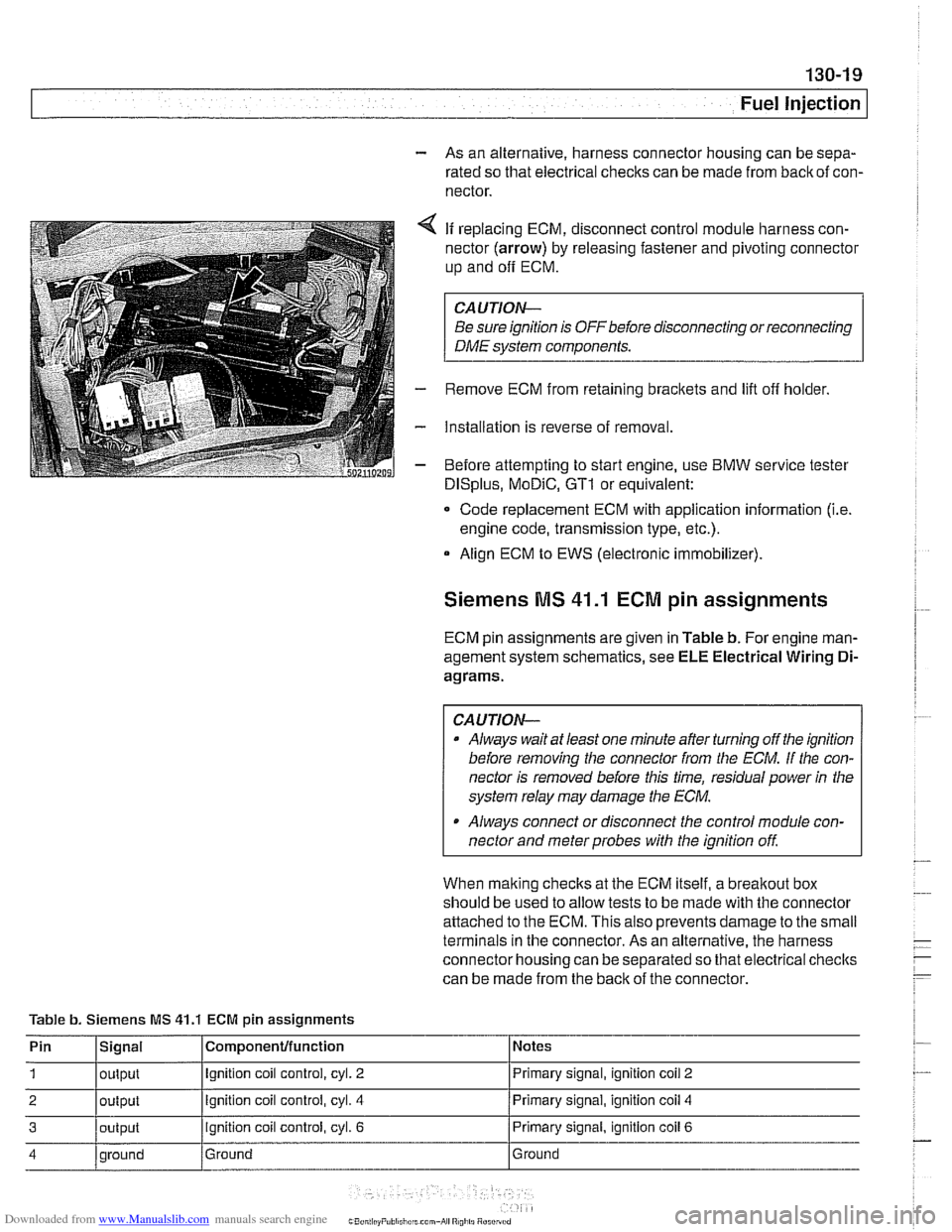
4 If replacing ECM, disconnect control module harness con-
nector (arrow) by releasing fastener and pivoting connector
up and
off ECM.
CAUTION-
Be sure ignition is OFF before disconnecting or reconnecting
DME system components.
- Remove ECM from retaining brackets and lift off holder.
- Installation is reverse of removal.
- Before attempting to start engine, use BMW service tester
DISplus, MoDiC, GTI or equivalent:
- Code replacement ECM with application information (i.e.
engine code, transmission type, etc.).
Align ECM to EWS (electronic immobilizer).
Siemens MS 41.1 ECM pin assignments
ECM pin assignments are given in Table b. For engine man-
agement system schematics, see ELE Electrical Wiring
Di-
agrams.
CAUTION-
a Always wait at least one minute after turning off the ignition
before removing the connector from the
ECM. If the con-
nector is removed before this time, residual power
in the
system relay may damage the
ECM.
Always connect or disconnect the control module con-
nector and meter probes with the ignition
off
When malting checks at the ECM itself, a breakout box
should be used to allow tests to be made with the connector
attached to the ECM. This also prevents damage to the small
terminals in the connector. As an alternative, the harness
connector housing can be separated so that electrical checlts
can be made from the back of the connector.
Table b. Siemens MS
41.1 ECM pin assignments
Pin
1
2
3
4
Signal
output
output
output
qround Componenfffunction
Ignition coil control, cyl. 2
Ignition coil control, cyl. 4
ignition coil control, cyl. 6
Ground Notes
Primary signal,
ignition
coil 2
Primary signal, ignition coil 4
Primary signal, ignition coil 6
Ground
Page 410 of 1002
Downloaded from www.Manualslib.com manuals search engine
I Fuel Injection
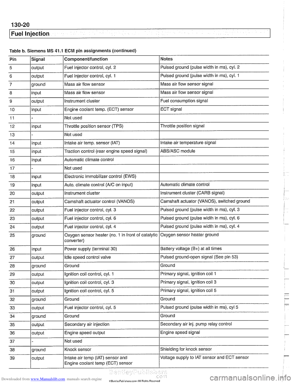
Table b. Siemens MS 41.1 ECM pin assignments (continued)
Pin
l~iqnal I Componentlfunction 1 Notes I - I I
5 loutput I Fuel injector control, cyl. 2 I Pulsed ground (pulse width in ms), cyl. 2 I I I
6 loutput /Fuel injector control, cyi. 1 I Pulsed ground (pulse width in ms), cyl. 1
I I I
14 linput I Intake air temp. sensor (IAT) I Intake air temperature signal
- 7
8
9
10
11
12
13
ground
input
output
input
input
15
16
17 18
19
20
21
22
I - I I
35 loutput /Secondary air injection ISecondary air inj. pump relay control
25
26
27
28
29
30
31
32
33
36
/output I Engine speed output IEngine speed signal
Mass air flow sensor
Mass air flow sensor
instrument cluster
Engine coolant
temp.
(ECT) sensor
Not used
Throttle position sensor (TPS)
Not used
input
input
input
input
output
output
out~ut
37 1 - /Not used I
Mass air flow sensor signal
Mass air flow sensor signal
Fuel consumption signal
ECT signal
Throttle position signal
ground
input
output
ground
output
output
output
ground
output
Traction control (rear engine speed signal) Automatic climate control
Not used Electronic immobilizer control (EWS)
Auto. climate control
(AIC on input)
instrument
cluster
Camshaft actuator control (VANOS)
Fuel iniector control, cvl.
3
AES/ASC module
Automatic climate control instrument cluster (CARE signal)
Camshaft actuator (VANOS), switched ground
Pulsed ground (pulse width in
ms), cyl. 3
Oxygen sensor heater (no. 1 in front of catalytic
converter)
Power supply (terminal
30)
Idle speed control valve
Ground
Ignition coil control, cyl.
1
Ignition coil control, cyl. 3
Ignition coil control, cyl. 5
Ground Fuel injector control, cyl.
5
Oxygen sensor heater ground
Battery voltage
(E+) at all times
Pulsed ground-open signal (See pin
53)
Ground
Primary signal, ignition coil
1
Primary signal, ignition coil 3
Primary signal, ignition coil 5
Ground
Pulsed ground (pulse width in ms), cyl
5
Page 414 of 1002
Downloaded from www.Manualslib.com manuals search engine
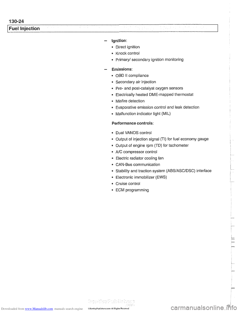
Fuel Injection
- Ignition:
Direct ignition
Knock control
4 Primary1 secondary ignition monitoring
- Emissions:
OBD II compliance
Secondary air injection
Pre- and post-catalyst oxygen sensors
0 Electrically heated DME-mapped thermostat
Misfire detection
Evaporative emission control and
leak detection
Malfunction indicator light (MIL)
Performance controls:
Dual VANOS control
Output of injection signal (TI) for fuel economy gauge
Output of engine rpm (TD) for tachometer
AIC compressor control
0 Electric radiator cooling fan
CAN-Bus communication
Stability and traction system
(ABSIASCIDSC) interlace
Electronic immobilizer (EWS)
Cruise control
ECM programming
Page 431 of 1002
Downloaded from www.Manualslib.com manuals search engine
. -
Fuel Injection I
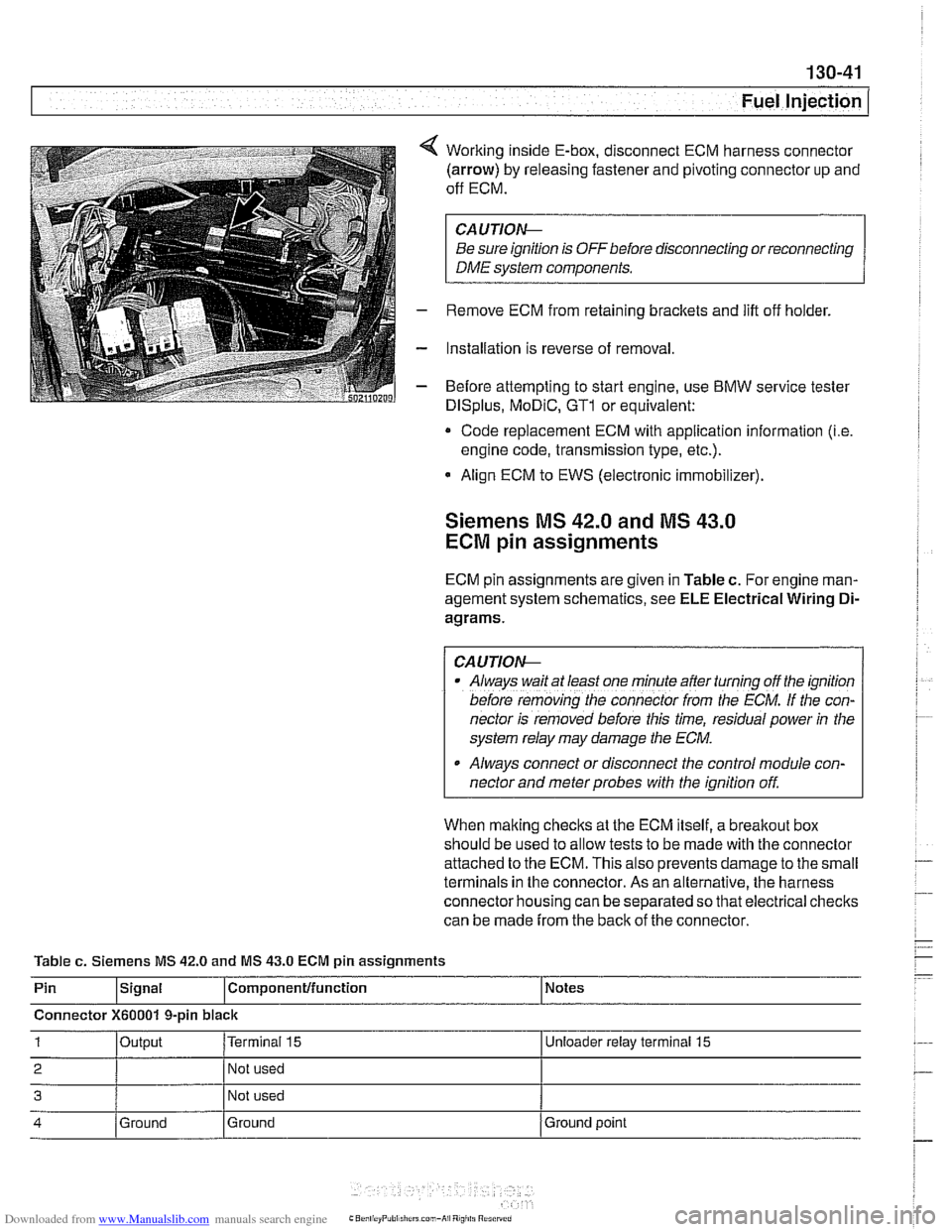
Working inside E-box, disconnect ECM harness connector
(arrow) by releasing fastener and pivoting connector up and
off ECM.
CA UTIOW
Be sure ignition is OFF before disconnecting or reconnecting
DME system components.
Remove ECM from retaining brackets and lift off holder.
Installation is reverse of removal
Before attempting to start engine, use
BMW service tester
DISplus, MoDiC, GTl or equivalent:
* Code replacement ECM with application information (i.e
engine code, transmission type, etc.).
Align ECM to EWS (electronic immobilizer).
Siemens MS 42.0 and MS 43.0
ECM pin assignments
ECM pin assignments are given in Table c. For engine man-
agement system schematics, see
ELE Electrical Wiring Di-
agrams.
/ CAUTIOW I
Al~ays wait at least one mfnule after turning off the ignition
before
remov;ng [he connecror irom rhe ECM. If the con-
nector is removed before this time, residual power
in the
system relay may damage the
ECM.
Always connect or disconnect the control module con-
nector and meter probes with the ignition off.
When making checks at the ECM itself, a
breakout box
should be used to allow tests to be made with the connector
attached to the ECM. This also prevents damage to the small
terminals in the connector. As an alternative, the harness
connector housing can be separated so that electrical checks
can be made from the back of the connector.
Table
c. Siemens MS 42.0 and MS 43.0 ECM pin assignments
Pin
lslgnal l~om~onentlfunction 1 Notes
Connector
X60001 9-pin black
1 loutput I~erminai 15 I Unloeder relay terminal 15
2 I 1 Not used I
3 Not used
4 Ground
Ground Ground
point
Page 449 of 1002
Downloaded from www.Manualslib.com manuals search engine
130-59
Fuel Injection
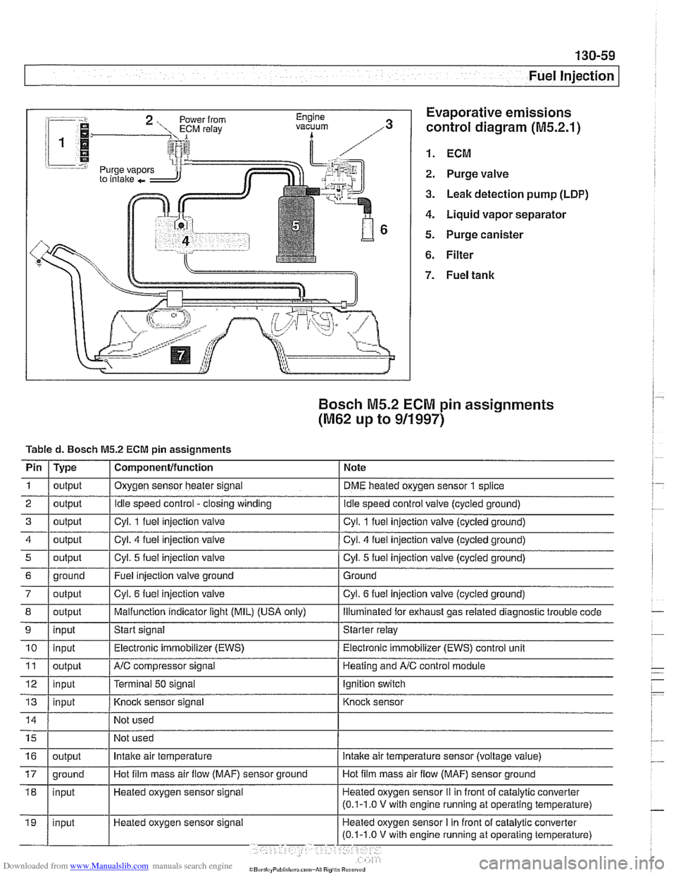
:-- -i. Evaporative emissions
1.
control diagram (M5.2.1)
i 1
i I @ 1. ECM r.=.:-:, 2. Purge valve
3. Leak detection pump (LDP)
4. Liquid vapor separator
5. Purge canister
6. Filter
Bosch M5.2 ECM pin assignments
(M62 up to 911997)
Tabled. Bosch M5.2 ECM pin assignments
I' 1- 1. . . -
4 1 output / Cyl. 4 fuel injection valve I Cyl. 4 fuel injection valve (cycled ground)
Pin
1
2
3
i I
I
7 / output I Cyl. 6 fuel injection valve I Cyl. 6 fuel injection valve (cycled ground)
Type
output
output
output
I I ,
8 1 output I Malfunction indicator light (MIL) (USA only) I lliumlnated for exhaust gas related diagnostic trouble code
5
Component/function
Oxygen sensor heater signal
Idle speed control -closing winding
Cvl. 1 fuel iniection valve Note
DME heated oxygen sensor
1 splice
idle speed control valve (cycled ground)
Cvl. 1 fuel iniection valve lcvcled around)
6 1 ground I Fuel injection valve ground 1 Ground
output
9
Not
used
Not used
11
12
13
Cyl. 5 fuel injection valve
10 1 input I Electronic immobilizer (EWS) / Electronic immobilizer (EWS) control unit
input
Heated oxygen sensor signal Cyl.
5 fuel injection
valve (cycled ground)
output
input
input
16
Start signal Starter relay
NC compressor signal
Terminal
50 signal
Knock sensor signal
17 1 ground I Hot film mass air flow (MAF) sensor ground I Hot film mass air flow (MAF) sensor ground
output Heating and
A/C control module
Ignition switch
Knock sensor
Intake air temperature intake air temperature sensor (voltage value)
Page 455 of 1002
Downloaded from www.Manualslib.com manuals search engine
Fuel Injection
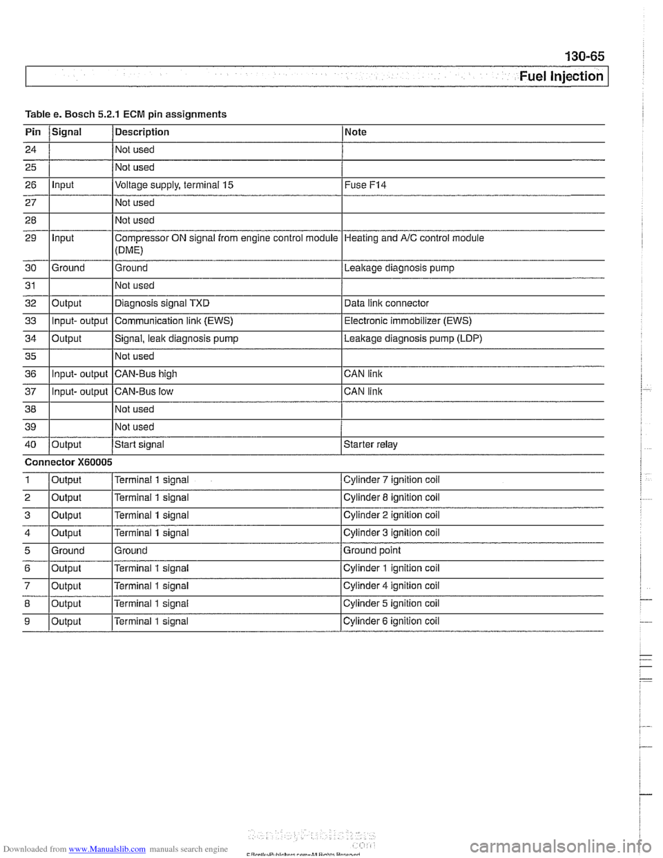
Table Pin
24
25
26
27
28
29
30
31
32
33
34
35
36
37
38
39
40
1
2
3
4
5
6
7
8
9
e. Bosch 5.2.1
Signal
Input
Input
Ground
Output Input- output
Output
Input- output
Input- output
Output
Connector
X60005
Output
Output
Output
Output
Ground
Output
Output
Output
Output
ECM pin assignments
Description
Not used
Not used
Voltage supply, terminal
15
Not used
Not used
Compressor ON signal from engine control module
(DME)
Ground
Not used
Diagnosis signal TXD
Communication
link (EWS)
Signal, leak diagnosis pump
Not used
CAN-Bus high
CAN-Bus low Not used
Not used
Start
signal
Terminal 1 signal
Terminal
1 signal
Terminal
1 signal
Terminal
1 signal
Ground
Terminal
1 signal
Terminal
1 signal
Terminal
1 signal
Terminal 1 signal Note
Fuse
F14
Heating
and AIC control module
Lealtage diagnosis pump
Data
iinit connector
Electronic immobilizer (EWS)
Leakage diagnosis pump (LDP)
CAN link
CAN link
Starter relay
Cylinder
7 ignition coil
Cylinder 8 ignition coil
Cylinder
2 ignition coil
Cylinder
3 ignition coil
Ground point
Cylinder
1 ignition coil
Cylinder
4 ignition coil
Cylinder 5 ignition coil
Cylinder
6 ignition coil
Page 469 of 1002
Downloaded from www.Manualslib.com manuals search engine
Fuel Injection I
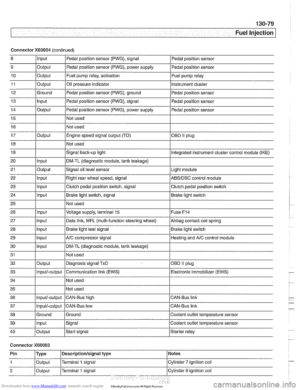
Connector X60004 (continued)
8 10
11
12
13
14
15
16
9
Output 0
Input
17
18
19
20
21
22
23
24
25
26
27
28
29
30
31
32
33
34
35
36
39
llnput lsignal l~oolant outlet temperature sensor
Output
Output
Ground
Input
Output
I I - I
40 /output Istart signal Istarter relay
Pedal position sensor (PWG), signal
Output Input
Output
input
Input
Input
Input
Input
Input
input
Input
Output
Input/-output
Input/-output
37
Connector X60003
Pedal position sensor
Fuel pump relay, activation
Oil pressure indicator Pedal position sensor (PWG), ground
Pedal position sensor (PWG), signal
Pedal position sensor (PWG), power supply
Not used
Not used Fuel
pump relay
Instrument cluster
Pedal position sensor
Pedal position sensor
Pedal position sensor
Engine speed signal output (TD)
Not used
Signal
back-up light
DM-TL (diagnostic module,
tank leakage)
Signal oil level sensor
Right rear wheel speed, signal
Clutch pedal position switch, signal
Brake light switch, signal
Not used
Voltage supply, terminal
15
Data link, MFL (multi-function steering wheel)
Brake light test signal
AJC compressor signal
DM-TL (diagnostic module, tank
leakage)
Not used
Diagnosis signal
TxD
Communication link (EWS)
Not used
Not used
CAN-BUS hiqh
38 1 Ground l~round I Coolant outlet temperature sensor
OED II plug
Integrated instrument cluster control module (IKE)
Light module
ABSIDSC control module
Clutch pedal position switch
Brake light switch
Fuse
F14
Airbag contact coil spring
Brake light switch
Heating and
A/C control module
OBD
II plug
Electronic immobilizer (EWS)
CAN-Bus link
CAN-Bus link
Input/-output CAN-Bus low
Page 900 of 1002
Downloaded from www.Manualslib.com manuals search engine
51 5-6
(Central Locking and Anti-Theft
Each rear door is equipped with the child lock-out lever, pre-
venting the door from being opened from the inside regard-
less of loclc button position.
Starting with models produced afler
911997, the General
Module and electronic immobilizer (EWS) interface via the
K-
Bus to monitor double lock status and to initiate double loclc
override. This feature allows the doors to be opened from the
inside if a key accepted by EWS is switched on in the ignition.
See Single lock and double lock function.
The door loclc buttons are mechanically uncoupled from the
actuators when locked. The remote keyless entry system
(FZV) is standard equipment. This allows for elimination of
the passengers side door
loclt cylinder.
Another function of the locking system is the
sofl close trunk
(SCA) system, where applicable.
Single lock and double lock function
(2000 and later models)
On models produced after
911999, each door lock actuator in-
corporates two motors:
Single lock motor controls the mechanical loclc mechanism
when the central lock switch is pressed to single loclc the
vehicle. The loclc mechanism is fully locked at this point but
can stil. be openeo from
the interor by pulng the appropri-
are interior door nandle lwce or by pressing rhe central
lock switch again. When single
lock'function is activated,
the fuel filler flap actuator is not locked.
Double lock motor, also known as central arrest, is activat-
ed only when the vehicle is locked from the outside at the
driver's door lock with a key or when the GM receives a
lock request from the remote entry (FZV) system. In this
case the double lock motor is activated simultaneously
with the single lock motor. The function of the double loclc
motor is to mechanically offset an internal rod in the loclc
actuator, disabling it from unlocking the vehicle from the in-
terior. This prevents the doors from being unloclted by any
means except from an unlock request at the driver's door
or via the FZV remote key.
Lock cylinder safety
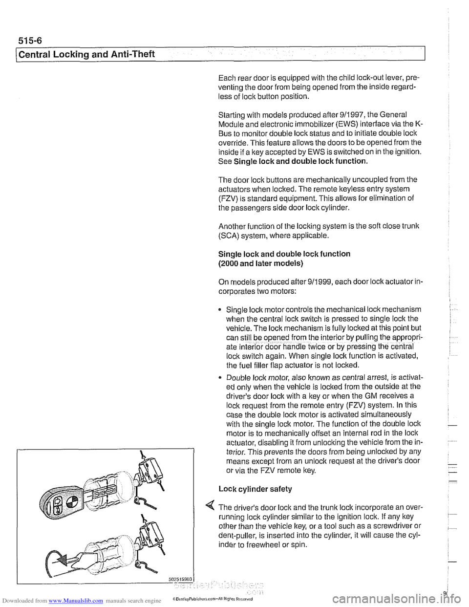
4 The driver's door loclc and the trunk loclc incorporate an over-
running loclc cylinder similar to the ignition lock. If any key
other than the vehicle key, or a tool such as a screwdriver or
dent-puller, is inserted into the cylinder, it will cause the cyl-
inder to freewheel or spin.
Page 904 of 1002
Downloaded from www.Manualslib.com manuals search engine
1 Central Locking and Anti-Theft
NOJE-
A single unlock request from the driver's door with the FZV
key unlocks the driver's door only.
A second unlock request
unlocls the remaining doors and trunk. This feature can be
modified for individual users with the Key Memory capabil-
ities to activate all lock actuators simultaneously See Car
Memory
/ Key Memory later in this section.
Starting with 2000 models, the battery in the FZV ignition
Icey is recharged by the ignition switch ring antenna while
the ley is in the ignition switch.
Transmitter self-test (models to
1999)
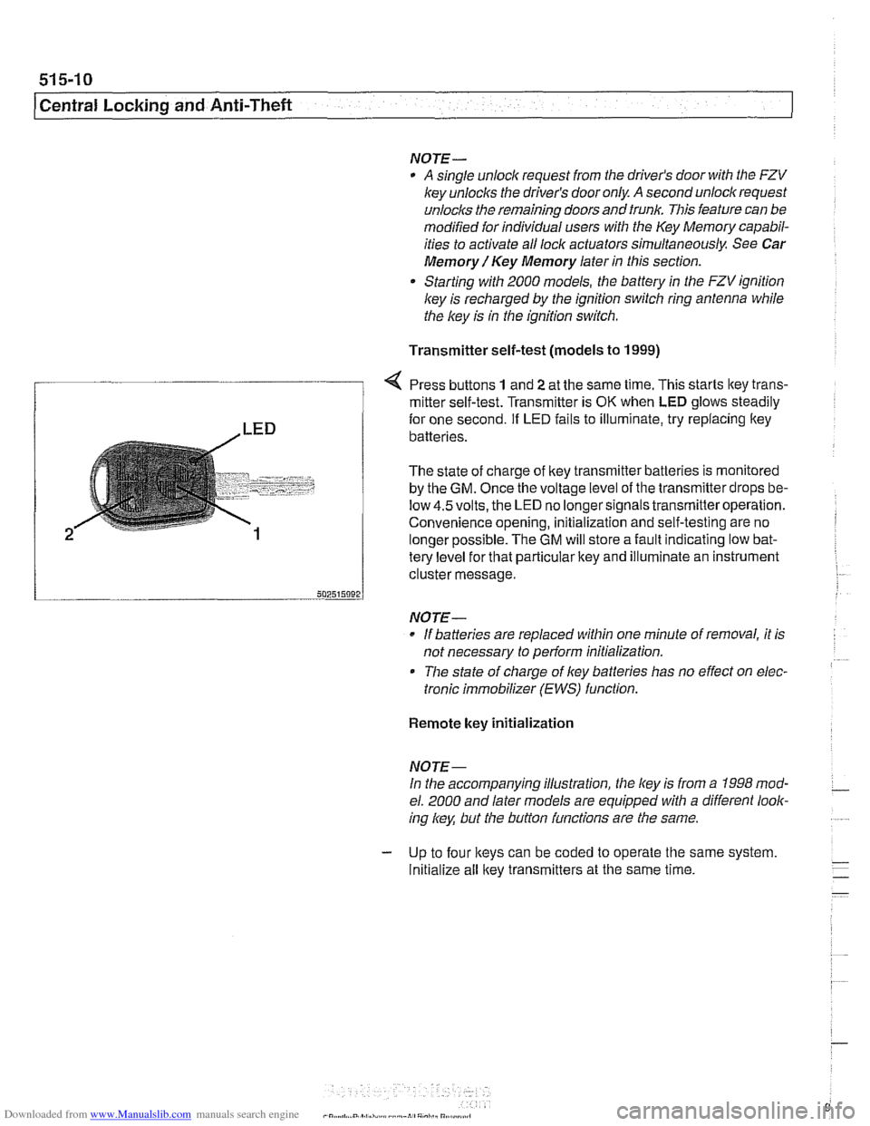
Press buttons 1 and 2 at the same time. This starts ltey trans-
/ mitter self-test. Transmitter is OK when LED glows steadily
te{le"el for that particular key and illuminate an instrument
cluster message.
-- 502515092 J
NO JE-
If batteries are replaced within one minute of removal, it is
not necessary to
periorm initialization.
Tlie state of charge of key batteries has no effect on elec-
tronic immobilizer (EWS) function.
2
Remote key initialization
for one second. If LED fails to illuminate, try replacing ltey~
batteries.
The state of charge of key transmitter batteries is monitored
by the
GM. Once the voltage level of the transmitter drops be-
low
4.5volts, the LED no longersignals transmitteroperation.
Convenience opening, initialization and self-testing are no
lonaer ~ossible. The GM will store a fault indicatina low bat-
NOJE-
In the accompanying illustration, the key is from a 1998 mod-
el. 2000 and later models are equipped with a different look-
ing
/
Initialize all key transmitters at the same time.