sensor BMW 540i 2000 E39 Workshop Manual
[x] Cancel search | Manufacturer: BMW, Model Year: 2000, Model line: 540i, Model: BMW 540i 2000 E39Pages: 1002
Page 29 of 1002
Downloaded from www.Manualslib.com manuals search engine
General
Cars with discharged or dead batteries can be jump-started
using the good battery from another car. See owner's manual
for proper instruction on jump starting. When jump-starling
the engine, always note the following warnings.
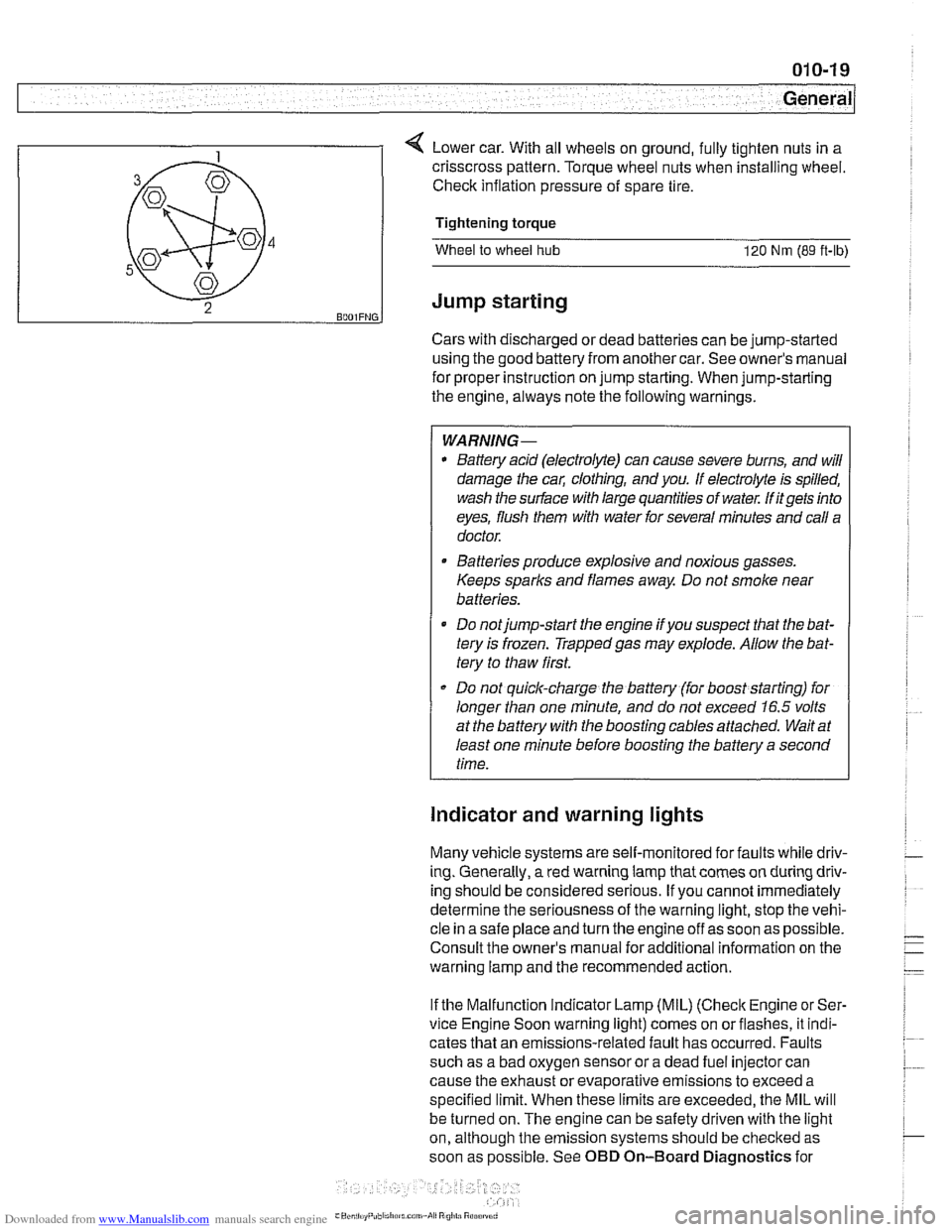
4 Lower car. With all wheels on ground, fully tighten nuts in a
WARNING-
* Battery acid (electrolyte) can cause severe burns, and will
damage the
cal; clothing, and you. If electrolyte is spilled,
wash the surface with large quantities of water.
M itgets into
eyes, flush them with water for several minutes and call a
doctor.
B4
5
43
2 BOOIFNG.
Batteries produce explosive and noxious gasses.
Keeps sparks and flames away. Do not smoke near
batteries.
Do notjump-start the engine
ifyou suspect that the bat-
tery is frozen. Trappedgas may explode. Allow the bat-
tery to thaw first.
Do not quick-charge the battery (for boost starting) for
longer than one minute, and do not exceed
16.5 volts
at the battery with the boosting cables attached. Wait at
least one minute before boosting the battery a second
time.
crisscross pattern.
Torque wheel nuts when installing wheel.
Check inflation pressure of spare tire.
Tightening torque
Wheel to wheel hub 120 Nm (89 ft-ib)
Jump starting
Indicator and warning lights
Many vehicle systems are self-monitored for faults while driv-
ing. Generally,
a red warning lamp that comes on during driv-
ing should be considered serious. If you cannot immediately
determine the seriousness of the warning light, stop the vehi-
cle in a safe place and turn the engine off as soon as possible.
Consult the owner's manual for additional information on the
warning lamp and the recommended action.
If the Malfunction Indicator Lamp (MIL)
(Check Engine or Ser-
vice Engine Soon warning light) comes on orflashes, it indi-
cates that an emissions-related fault has occurred. Faults
such as a bad oxygen sensor or a dead fuel injector can
cause the exhaust or evaporative emissions to exceed a
specified limit. When these limits are exceeded, the MIL will
be turned on. The engine can be safety driven with the light
on, although the emission systems should be
checked as
soon as possible. See OBD On-Board Diagnostics for
Page 33 of 1002
Downloaded from www.Manualslib.com manuals search engine
020 Maintenance
General ........................... .02 0.2
Special tools ........................ .02 0.2
Service Interval Indicator (Sll) ........... .02 0.3
Service Interval Indicator (Sll), resetting ... .02 0.3
Inspection I, Inspection 11 ............... .02 0.5
Maintenance Tables ................ .02 0.6
Fluid and Lubricant Specifications .. .02 0.9
Fluids and lubricants ................. .02 0.10
Engine Oil Service ................ .02 0.1 I
Engine oil. checking level ............. .02 0.12
Engine oil and filter. changing .......... .02 0-13
Engine Compartment Maintenance . .02 0.14
Accelerator and linkage ............... .02 0.14
Air filter. replacing ................... .02 0.1 4
Cooling system service ............... .02 0.15
Engine drive belt service .............. .02 0.16
Idlespeed .......................... 020-19
Catalytic converter and oxygen sensors .. .02 0.19
Power steering fluid, checking level ..... .02 0.20
Spark plugs ........................ .02 0.20
Spark plugs, replacing ................ .02 0.21
Interior ventilation microfilter, replacing ... .02 0.22
Other Mechanical Maintenance ..... .02 0.22
Battery, checking. cleaning. and replacing .02 0-22
Brake fluid. replacing ................. .02 0-24
Brake pad 1 rotor wear. checking ........ .02 0.24
Brake system, inspecting ............. .02 0.25
Parking brake. checking ............... 020-25
Clutch fluid. checking ................. 020-26
Differential oil level. checking ........... 020-26
Drive axle joint (CV joint) boots. inspecting 020-27
Exhaust system. inspecting ............ 020-27
Fuel filter. replacing .................. 020-27
Fuel tank and fuel lines. inspecting ...... 020-28
Suspension. front. inspecting ........... 020-29
Suspension. rear. inspecting ........... 020-29
Tires. checking inflation pressure ........ 020-29
Tires. rotating ....................... 020-29
Transmission service. automatic ........ 020-29
Transmission service. manual .......... 020-30
Transmission fluid. checking and filling
(manual transmission)
................ 020-30
Wheels. aligning ..................... 020-30
Body and Interior Maintenance ..... 020-31
Body and hinges. lubricating ........... 020-31
Exterior washing ..................... 020-31
Interior care ........................ 020-31
Leather upholstery and trim ............ 020-31
Polishing ........................... 020-32
Seat belts .......................... 020-32
Special cleaning ..................... 020-32
Washing chassis ..................... 020-32
Waxing ............................ 020-32
Windshield wiper blade maintenance ..... 020-33
Page 41 of 1002
Downloaded from www.Manualslib.com manuals search engine
--- -
Maintenance
Table c. Inspection II Service
Additional
New parts Warm engine Dealer service repair
Tools required required required recommended information
Engine compartment maintenance
Replace air filter element. (Note: reduce
replacement intervals in dusty operating
conditions).
Replace brake
fluid every 2 years (time
interval begins from vehicle production
date).
Cooling system service
Spark plug service
Brake
system maintenance
:j:
*
Replace coolant every 3 years (time
interval begins from vehicle production
date).
Replace oxygen sensor every 160,000
itm
(1 00,000 miles).
020
FLUID AND LUBRICANT
SPECIFICATIONS
:I:
Oxygen sensor service
*
x:
Spark plugs:
M52
1 M62 engine:
Replace every 60,000 itm (48.000 miles).
M52
TU I M54 1 M62 TU engine:
Replace every 160,000
ltm (100.000
miles).
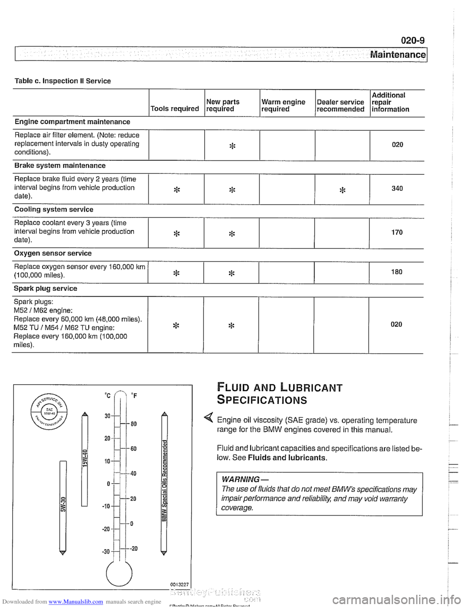
< Engine oil viscosity (SAE grade) vs. operating temperature
range for the BMW engines covered in this manual.
Fluid and lubricant capacities and specifications are listed be-
low. See
Fluids and lubricants.
:I:
*
*
*
WARNING -
The use of fluids that do not meet BMW" specifications may
impair performance and
reliabilitl: and may void warranty
coverage.
340
170
180
* 020
Page 47 of 1002
Downloaded from www.Manualslib.com manuals search engine
Maintenance
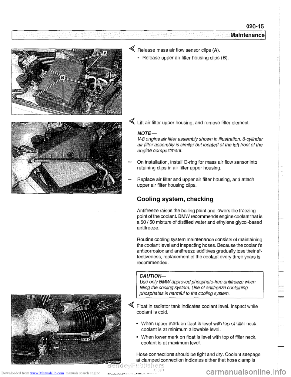
< Release mass air flow sensor clips (A).
Release upper air filter housing clips (B).
4 Lift air filter upper housing, and remove filter element.
NOTE-
V-8 engine air filter assembly shown in illustration. 6-cylinder
air filter assembly is similar but located at the left front of the
engine compartment.
- On installation, install O-ring for mass air flow sensor into
retaining clips in air filter upper housing.
- Replace air filter and upper air filter housing, and attach
upper air filter housing clips.
Cooling system, checking
Antifreeze raises the boiling point and lowers the freezing
~oint of the coolant. BMW recommends enaine coolantthat is
a 50 150 mixture of distilled water and ethGene glycol-based
antifreeze.
Routine cooling system maintenance consists of maintaining
the coolant level and inspecting hoses. Because the coolant's
anticorrosion and antifreeze additives gradually lose their ef-
fectiveness, replacement of the coolant every three years is
recommended.
CAUJION-
Use only BMWapprovedphosphate-free antifreeze when
filing the cooling system. Use of antifreeze containing
phosphates is harmful to the cooling system.
4 Float in radiator tank indicates coolant level. Inspect while
coolant is cold.
When upper mark on float is level with top of filler neck,
coolant is at minimum allowable level.
When lower mark on float is level with top of filler neck,
coolant is at maximum level.
Hose connections should be tight and dry. Coolant seepage
nnection indicates either that hose clamp is
Page 51 of 1002
Downloaded from www.Manualslib.com manuals search engine
Maintenance
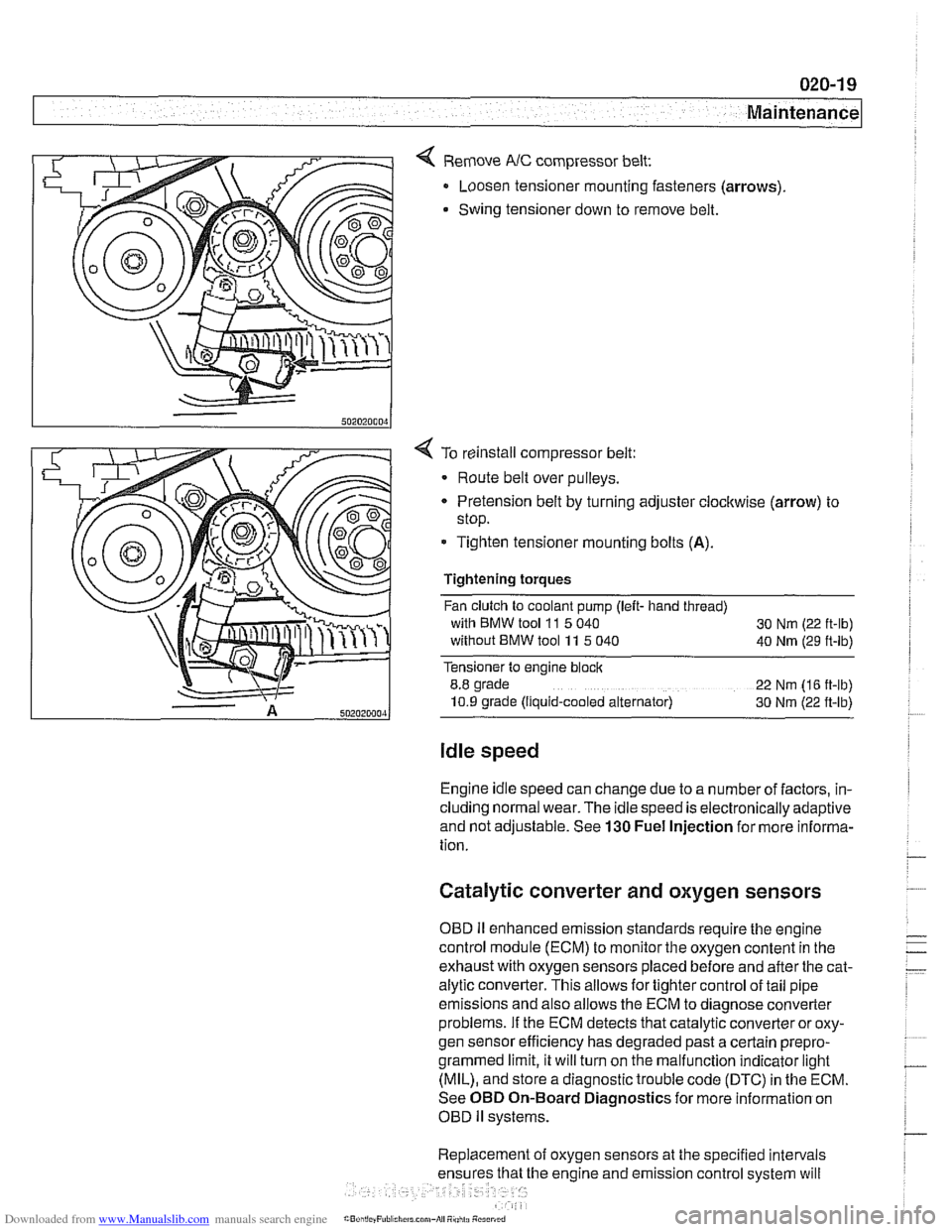
< Remove NC compressor belt:
Loosen tensioner mounting fasteners (arrows)
Swing tensioner down to remove belt.
4 To reinstall compressor belt:
Route belt over pulleys.
* Pretension belt by turning adjuster clockwise (arrow) to
stop.
- Tighten tensioner mounting bolts (A).
Tightening torques
Fan clutch to coolant pump (left- hand thread)
with BMW tool
11 5 040
30 Nm (22 ft-lb)
without BMW tool 11 5 040
40 Nm (29 ft-lb)
Tensioner to engine block
8.8 grade
22 Nm (16 ft-lb)
10.9 grade (Ilquid-cooled alternator) 30 Nm (22 ft-lb)
Idle speed
Engine idle speed can change due to a number of factors, in-
cluding normal wear. The idle speed is electronically adaptive
and not adjustable. See
130 Fuel Injection for more informa-
tion.
Catalytic converter and oxygen sensors
OBD II enhanced emission standards require the engine
control module (ECM) to monitor the oxygen content in the
exhaust with oxygen sensors placed before and after the cat-
alytic converter. This allows for tighter control of tail pipe
emissions and also allows the ECM to diagnose converter
problems. If the ECM detects that catalytic converter or oxy-
gen sensor efficiency has degraded past a certain
prepro-
grammed limit, it will turn on the malfunction indicator light
(MIL), and store a diagnostic trouble code (DTC) in the ECM.
See OBD On-Board Diagnostics for more information on
OBD
ll systems.
Replacement of oxygen sensors at the specified intervals
he engine and emission control system will
Page 52 of 1002
Downloaded from www.Manualslib.com manuals search engine
Maintenance
continue to operate as designed. Extending the replacement
interval may void the emission control warranty coverage.
See
180 Exhaust System for information on replacing the
oxygen sensors.
Tightening torque
Oxvoen sensor to exhaust
manifold 50 Nrn (37 ft-lb)
NOTE-
A special soclet for replacing the oxygen sensor is available
from most automotive parts stores. The soclet has
a groove
cut down one side to allow the sensor to be installed without
damaging the wire harness.
Power steering fluid, checking level
The power steering system is permanently filled and does not
have a drain. Routinely adding ATF is not required unless the
system is leaking.
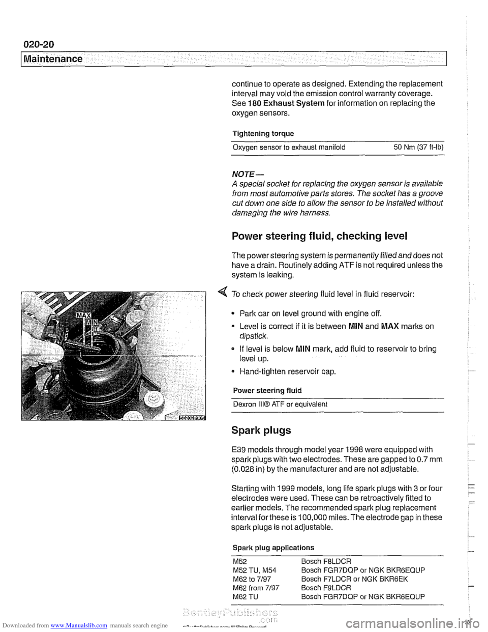
4 To check power steering fluid level in fluid reservoir:
Park car on level ground with engine off.
Level is correct
if it is between MlN and MAX marks on
dipstick.
If level is below
MlN mark, add fluid to reservoir to bring
level up.
* Hand-tighten reservoir cap.
Power steering fluid
Dexron
1iiO ATF or equivalent
Spark plugs
E39 models through model year 1998 were equipped with
spark plugs with two electrodes. These are gapped to
0.7 mm
(0.028 in) by the manufacturer and are not adjustable.
Starting with 1999 models, long life spark plugs with
3 or four
electrodes were used. These can be retroactively fitted to
earlier
models. The recommended spark plug replacement
interval
forthese is 100,000 miles.The electrode gap in these
spark plugs is not adjustable.
Spark plug applications
M52 Bosch FBLDCR
M52 TU, M54 Bosch FGR7DQP or NGK BKRBEQUP
M62 to 7/97 Bosch F7LDCR or NGK BKR6EK
M62 from 7/97 Bosch F9LDCR
M62 TU Bosch FGR7DQP or NGK BKRGEQUP
Page 69 of 1002
Downloaded from www.Manualslib.com manuals search engine
Engine identifying features
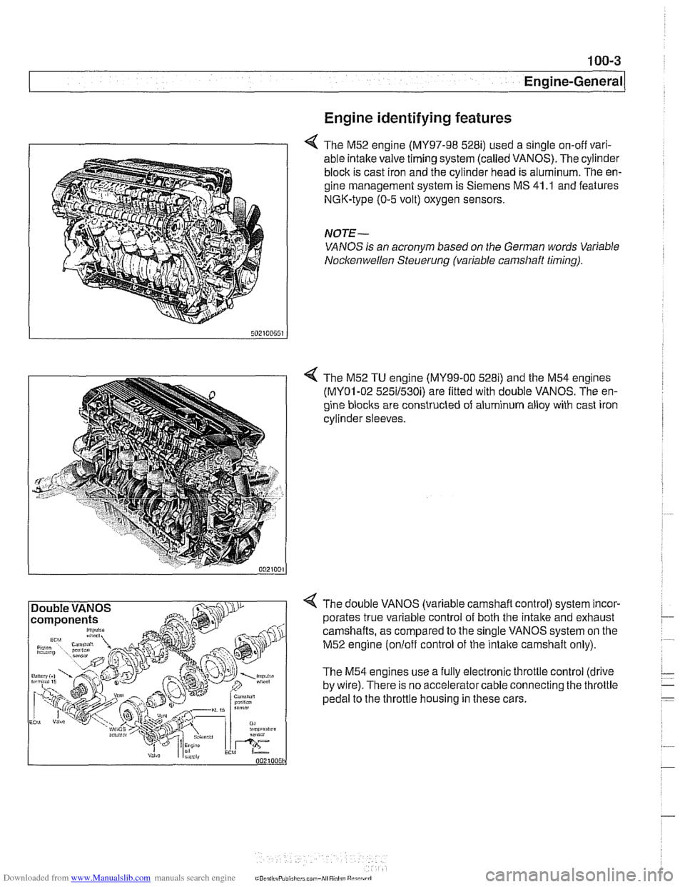
4 The M52 engine (MY97-98 528i) used a single on-off vari-
able intake valve timing system (called VANOS). The cylinder
block is cast iron and the cylinder head is aluminum. The en-
gine management system is Siemens MS 41
.I and features
NGK-type (0-5 volt) oxygen sensors.
NOTE-
VANOS is an acronym based on the German words Variable
Nocltenwellen Steuerung (variable camshaft timing).
4 The M52 TU engine (MY99-00 5281) and the M54 engines
(MY01-02 525il530i) are fitted with double VANOS. The en-
gine
blocits are constructed of aluminum alloy with cast iron
cylinder sleeves.
4 The double VANOS (variable camshaft control) system incor-
porates true variable control of both the
intake and exhaust
camshafts, as compared to the single VANOS system on the
M52 engine
(onloff control of the intaite camshaft only).
The M54 engines use a fully electronic throttle control (drive
by wire). There is no accelerator cable connecting the throttle
pedal to the throttle housing in these cars.
Page 77 of 1002
Downloaded from www.Manualslib.com manuals search engine
Engine Removal and lnstallationl
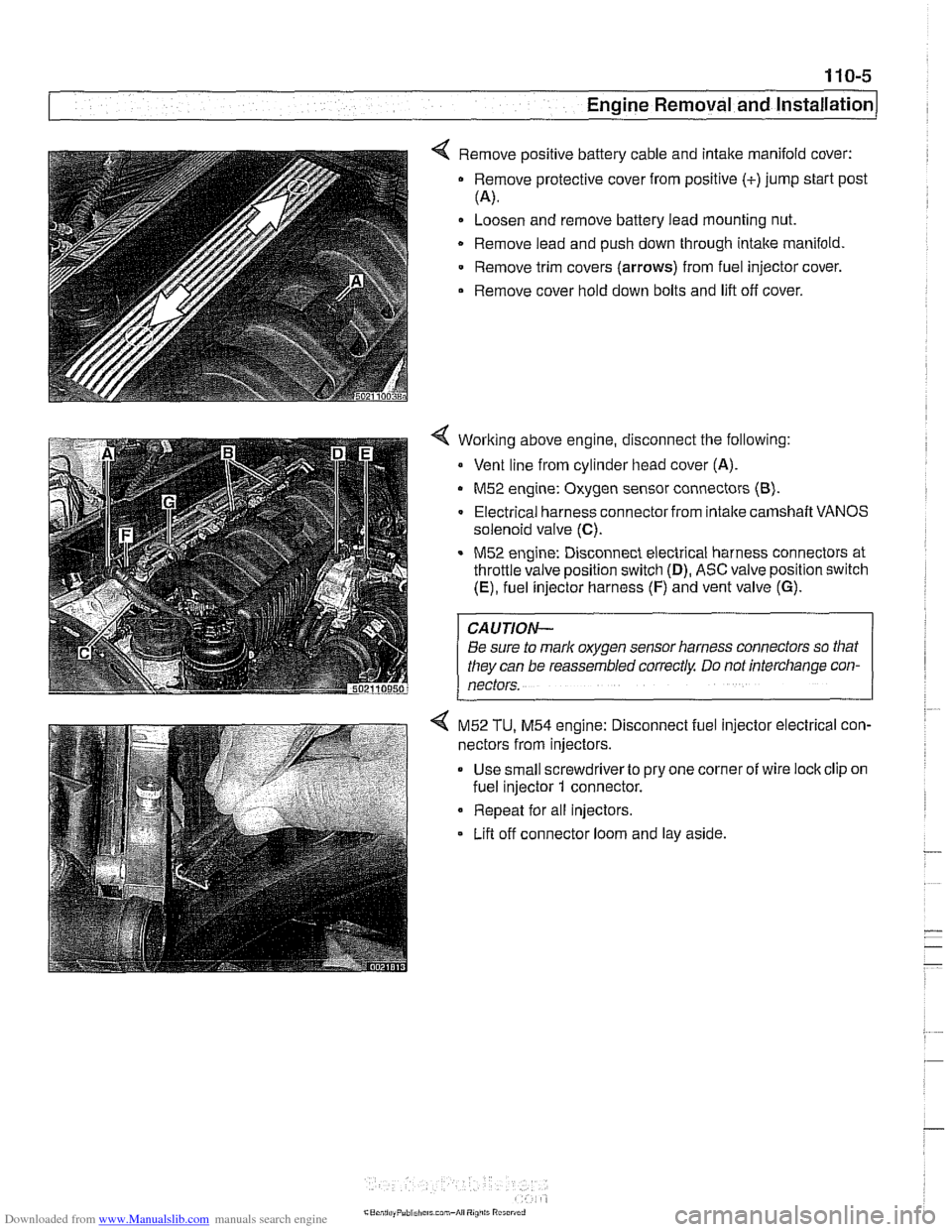
< Remove positive battery cable and intake manifold cover:
Remove protective cover from positive (+)jump start post
(4.
Loosen and remove battery lead mounting nut.
Remove lead and push down through intake manifold
Remove trim covers
(arrows) from fuel injector cover.
Remove cover hold down bolts and lift off cover.
Working above engine, disconnect the following:
Vent line from cylinder head cover (A).
M52 engine: Oxygen sensor connectors (8).
Electrical harness connector from intalte camshaft VANOS
solenoid valve
(C).
M52 engine: Disconnect electrical harness connectors at
throttle valve position switch
(D), ASC valve position switch
(E), fuel injector harness (F) and vent valve (G).
CAUTION-
Be sure to mark oxygen sensor harness connectors so that
they can be reassembled correctly Do not interchange con-
nectors.
4 M52 TU, M54 engine: Disconnect fuel injector electrical con-
nectors from injectors.
Use small screwdriverto pry one corner of wire lock clip on
fuel injector
1 connector.
Repeat for all injectors.
Lifl off connector loom and lay aside.
Page 81 of 1002
Downloaded from www.Manualslib.com manuals search engine
Engine Removal and lnstallationl
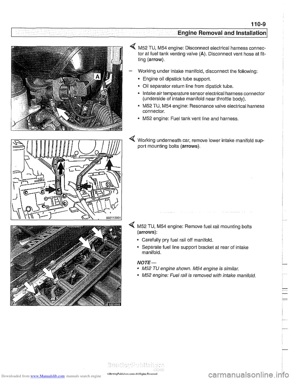
M52 TU, M54 engine: Disconnect electrical harness connec-
tor at fuel tank venting valve
(A). Disconnect vent hose at fit-
ting (arrow).
- Working under intake manifold, disconnect the following:
Engine oil dipstick tube support.
Oil separator return line from
dipsticlc tube.
Intake air temperature sensorelectrical harness connector
(underside of intake manifold near throttle body).
M52 TU, M54 engine: Resonance valve electrical harness
connector.
M52 engine: Fuel tank vent line and harness.
< Working underneath car, remove lower intalte manifold sup-
port mounting bolts (arrows).
4 M52 TU. M54 engine: Remove fuel rail mounting bolts
(arrows):
Carefully pry fuel rail off manifold.
Separate fuel line support bracket at rear of intake
manifold.
NOTE-
* M52 TU engine shown. M54 engine is similar.
M52 engine: Fuel rail is removed with intalte manifold.
Page 86 of 1002
Downloaded from www.Manualslib.com manuals search engine
110-14
I Engine Removal and Installation
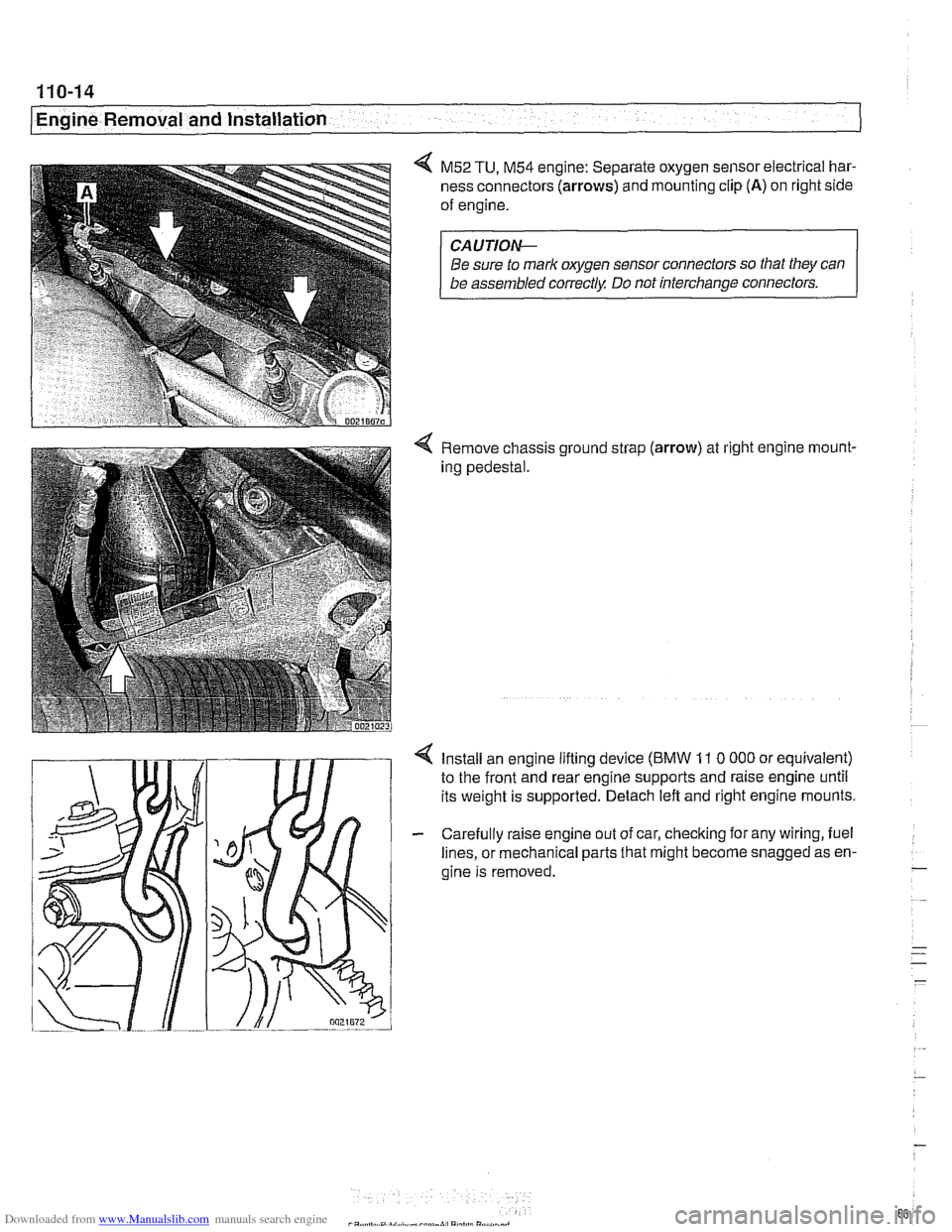
4 M52 TU, M54 engine: Separate oxygen sensor electrical har-
ness connectors
(arrows) and mounting clip (A) on right side
of engine.
CA UTIOW
Be sure to mark oxygen sensor connectors so that they can
be assembled correctly Do not interchange connectors.
4 Remove chassis ground strap (arrow) at right engine rnount-
ing pedestal.
4 Install an engine lifting device (BMW 11 0 000 or equivalent)
to the front and rear engine supports and raise engine until
its weight is supported. Detach left and right engine mounts.
- Carefully raise engine out of car, checking for any wiring, fuel
lines, or mechanical parts that might become snagged as en-
gine is removed.
-
. ..
- .- -
-