stop start BMW 540i 2000 E39 Workshop Manual
[x] Cancel search | Manufacturer: BMW, Model Year: 2000, Model line: 540i, Model: BMW 540i 2000 E39Pages: 1002
Page 29 of 1002

Downloaded from www.Manualslib.com manuals search engine
General
Cars with discharged or dead batteries can be jump-started
using the good battery from another car. See owner's manual
for proper instruction on jump starting. When jump-starling
the engine, always note the following warnings.
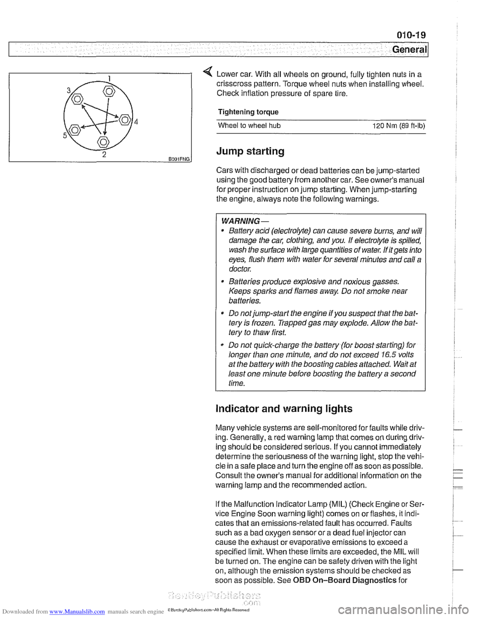
4 Lower car. With all wheels on ground, fully tighten nuts in a
WARNING-
* Battery acid (electrolyte) can cause severe burns, and will
damage the
cal; clothing, and you. If electrolyte is spilled,
wash the surface with large quantities of water.
M itgets into
eyes, flush them with water for several minutes and call a
doctor.
B4
5
43
2 BOOIFNG.
Batteries produce explosive and noxious gasses.
Keeps sparks and flames away. Do not smoke near
batteries.
Do notjump-start the engine
ifyou suspect that the bat-
tery is frozen. Trappedgas may explode. Allow the bat-
tery to thaw first.
Do not quick-charge the battery (for boost starting) for
longer than one minute, and do not exceed
16.5 volts
at the battery with the boosting cables attached. Wait at
least one minute before boosting the battery a second
time.
crisscross pattern.
Torque wheel nuts when installing wheel.
Check inflation pressure of spare tire.
Tightening torque
Wheel to wheel hub 120 Nm (89 ft-ib)
Jump starting
Indicator and warning lights
Many vehicle systems are self-monitored for faults while driv-
ing. Generally,
a red warning lamp that comes on during driv-
ing should be considered serious. If you cannot immediately
determine the seriousness of the warning light, stop the vehi-
cle in a safe place and turn the engine off as soon as possible.
Consult the owner's manual for additional information on the
warning lamp and the recommended action.
If the Malfunction Indicator Lamp (MIL)
(Check Engine or Ser-
vice Engine Soon warning light) comes on orflashes, it indi-
cates that an emissions-related fault has occurred. Faults
such as a bad oxygen sensor or a dead fuel injector can
cause the exhaust or evaporative emissions to exceed a
specified limit. When these limits are exceeded, the MIL will
be turned on. The engine can be safety driven with the light
on, although the emission systems should be
checked as
soon as possible. See OBD On-Board Diagnostics for
Page 46 of 1002

Downloaded from www.Manualslib.com manuals search engine
020-1 4
Maintenance
- When oil flow has diminished to an occasional drip, reinstall
drain plug with a new metal sealing washer and torque plug.
Tightening torque Engine oil drain plug to oil pan
25 Nrn (1.8 ft-lb)
6-cylinder oil filter assembly
r------ 1
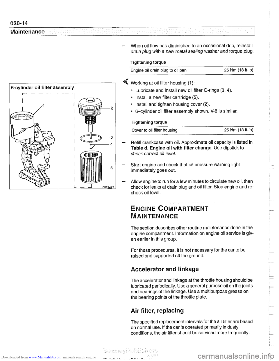
< Working at oil filter housing (1):
Lubricate and install new oil filter O-rings (3, 4).
Install a new filter cartridge (5).
lnstall and tighten housing cover (2).
6-cylinder oil filter assembly shown, V-8 is similar.
Tightening torque Cover to oil filter housing
25 Nm (1.8 it-lb)
- Refill crankcase with oil. Approximate oil capacity is listed in
Tabled. Engine oil with filter change. Use dipstick to
check correct oil level.
- Start engine and check that oil pressure warning light
immediately goes out.
- Allow engine to run fora few minutes to circulate new oil, then
check for leaks at drain plug and oil filter. Stop engine and re-
check oil level
The section describes other routine maintenance done in the
engine compartment. Information on engine oil service is
giv-
enkar~ier inthis group.
For these procedures, it is not necessary for the car to be
raised and supported off the ground.
Accelerator and linkage
The accelerator and linkage at the throttle housing should be
lubricated periodically. Use ageneral purposeoil on the joints
and bearings of the linkage. Use a multipurpose grease on
the bearing points of the throttle plate.
Air filter, replacing
The specified replacement intervals forthe air filter are based
on normal use. If the car is operated primarily in dusty
conditions, the air filter should be serviced more frequently.
Page 983 of 1002
![BMW 540i 2000 E39 Workshop Manual Downloaded from www.Manualslib.com manuals search engine
OBD-23
On-Board ~iagnostics]
I I
PI625 / 147 I Pedal Position Sensor Potentiometer Supply Channel 2 Electrical 1
Engine diagnostic troubl BMW 540i 2000 E39 Workshop Manual Downloaded from www.Manualslib.com manuals search engine
OBD-23
On-Board ~iagnostics]
I I
PI625 / 147 I Pedal Position Sensor Potentiometer Supply Channel 2 Electrical 1
Engine diagnostic troubl](/img/1/2822/w960_2822-982.png)
Downloaded from www.Manualslib.com manuals search engine
OBD-23
On-Board ~iagnostics]
I I
PI625 / 147 I Pedal Position Sensor Potentiometer Supply Channel 2 Electrical 1
Engine diagnostic trouble codes: M54 engine (continued)
P-code
BMW-FC Explanation
PI 604
PI604
PI619
PI620
PI624
PI632
PI633
PI634
P1 634
PI 634
PI 635
PI 636 50
51 123
123
146 i I
I
I Barometric Pressure Circuit Low
Control
Module Self-Test,
Speed Monitoring
Control Module Self-Test, Speed Monitoring
Map Cooling Thermostat Control Circuit Signal Low
Map Cooling Thermostat Control Circuit Signal High Pedal Position Sensor Potentiometer Supply Channel
1 Electrical (M52: Coolant Thermostat (Coolant
Temperature Below Thermostat Regulating Temperature))
115
115
115
135
136
115
109
PI639
PI675
PI694
P2088
P2089
P2090
P2091
I I
P2229 1197 I Barometric Pressure Circuit High
Throttle
Valve Adaptation Conditions Not Met
Throttle
Valve Adaptation Limp-Home Position Unknown
Throttle Valve Adaptation Spring Test Failed
Throttle
Valve Adaptation Spring Test Failed
Throttle
Valve Adaptation Spring Test Failed
Throttle Valve Adaptation Lower Mechanical Stop not Adapted
Throttle Valve Control Circuit
Throttle Valve Position Control, Control Deviation
PI 637
I I
P2270 1215 1 02 Sensor Signal Stuck Lean (Banic 1 Sensor 2)
PI 638 1160 I Throttle Valve Position Control Throttle Stucic Temporarily
162
161
135
136
21
21 19
19 Throttle
Valve Position Control Throttle
Stucic Permanently
Throttle Valve Actuator Start Test Re-Adaptation Required
Throttle Valve Actuator Start Test Spring Test and Limp-Home Position Failed
'A' Camshaft Position Actuator Control Circuit Low (Banlc 1)
'A' Camshaft Position Actuator Control Circuit High (Banlc 1)
'B' Camshaft Position Actuator Control Circuit Low (Bank 1)
'B' Camshaft Position Actuator Control Circuit High (Bank 1)
P2271
P2272
P2273
P3041
P3198 I I -
215
216
21 6
10481
10205 02
Sensor Signal Stucic Lean (Bank 1 Sensor 2)
02 Sensor Signal
Stuclc Lean (Bank 2 Sensor 2)
02 Sensor Signal Stuclc Lean (Bank 2 Sensor 2)
02 Sensor Lean and Rich Voltage Thresholds not Reached (Bank 2 Sensor 2)
Engine Coolant Temperature Gradient Too High
Engine Coolant Temperature Signal Stuck
P3199
P3238 1 10289 I Control Module Monitoring TPU Chip Defective
10207
Page 989 of 1002

Downloaded from www.Manualslib.com manuals search engine
On-Board ~ia~nosticsl
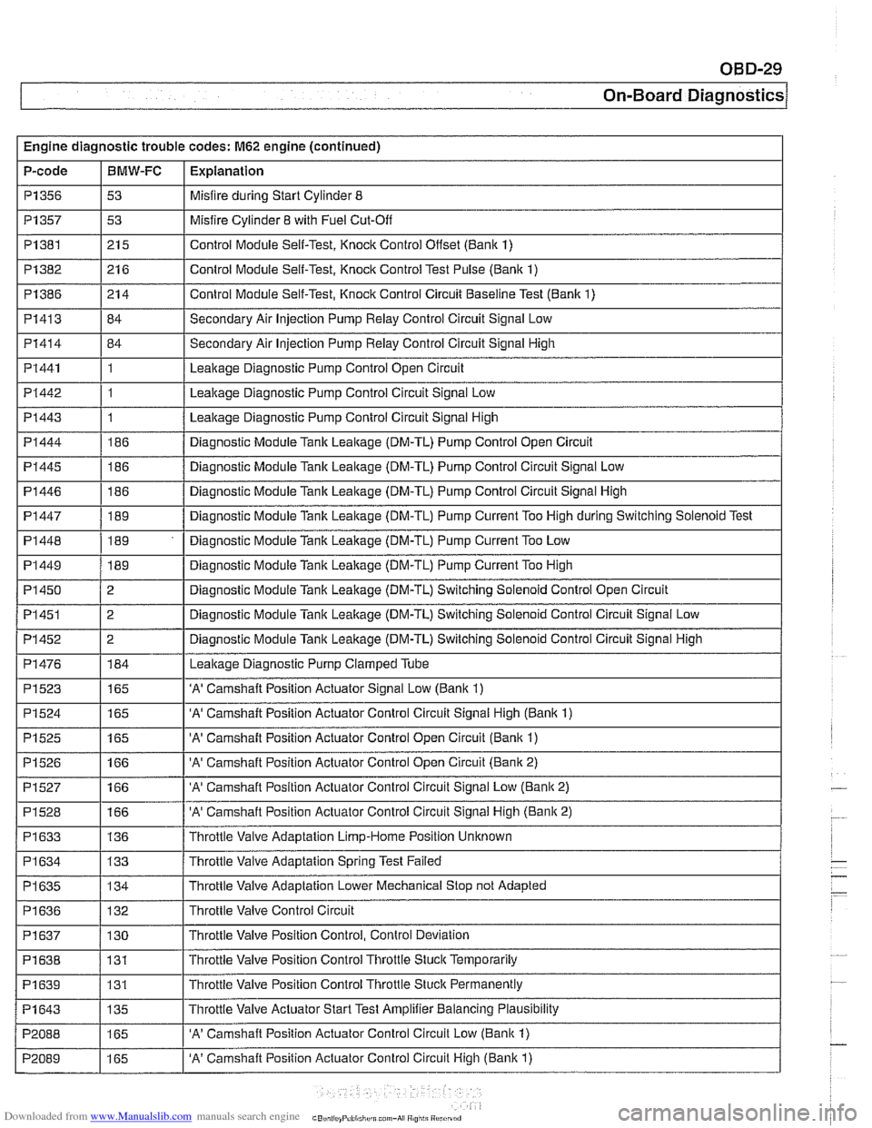
Engine diagnostic trouble codes: M62 engine (continued)
P-code
I I -
I I - -.
PI445 1186 / Diagnostic Module Tank Leakage (DM-TL) Pump Control Circuit Signal Low
PI357
PI382
PI386
PI413
PI414
PI441
PI442
PI443
PI444
P1356 1 53 I Misfire during Start Cylinder 8
BMW-FC
I P1523
I
I - -
1165 I 'A' Camshaft Position Actuator Signal Low (Banlc 1)
Explanation
P1381 1215 I Control Module Self-Test, Knock Control Onset (Bank 1)
53
21 6
21 4
84
84
1
1
1
186
PI 446
PI 447
PI 448
PI449
PI 450
PI451
PI452
PI476
Misfire Cylinder 8 with Fuel Cut-Off
Control Module Self-Test, Knock Control Test Pulse (Bank 1)
Control Module Self-Test, Knock Control Circuit Baseline Test (Bank 1)
Secondary Air Injection Pump Relay Control Circuit Signal Low
Secondary Air Injection Pump
Relay Control Circuit Signal High
Leakage Diagnostic Pump Control Open Circuit
Leakage Diagnostic Pump Control Circuit Signal Low
Leakage Diagnostic Pump Control Circuit Signal High
Diagnostic Module Tank Leakage (DM-TL) Pump Control Open Circuit
186
189
189
189
2
2
2
184
P1524
P1525
P1526
PI527
PI528
PI633
PI 634
PI 635
I I
PI 638 / 131 I Throttle Valve Position Control Throttle Stuck Temporarily
. -
Diagnostic Module Tank Leakage (DM-TL) Pump Control Circuit Signal High
Diagnostic Module
Tank Leakage (DM-TL) Pump Current Too High during Switching Solenoid Test
Diagnostic Module Tank Leakage (DM-TL) Pump Current Too Low
Diagnostic Module
Tank Leakage (DM-TL) Pump Current Too High
Diagnostic Module Tank Leakage (DM-TL) Switching Solenoid Control Open Circuit
Diagnostic Module
Tank Leakage (DM-TL) Switching Solenoid Control Circuit Signal Low
Diagnostic Module
Tank Leakage (DM-TL) Switching Solenoid Control Circuit Signal High
Leakaqe Diaqnostic Pump Clamped Tube
I I
165
165
166
166
166
136
133
134
'A' Camshaft Position Actuator Control Circuit Signal High (Banlc 1)
'A' Camshaft Position Actuator Control Open Circuit (Bank 1)
'A' Camshaft Position Actuator Control Open Circuit (Bank 2)
'A' Camshaft Position Actuator Control Circuit Signal Low (Bank 2)
'A' Camshaft Position Actuator Control Circuit Signal High (Bank 2)
Throttle Valve Adaptation Limp-Home Position Unknown
Throttle Valve Adaptation Spring Test Failed
Throttle Valve Adaptation Lower Mechanical Stop not Adapted
Throttle Valve Control Circuit
PI 636
PI639
P1643
P2088
P2089
PI 637 / 130 I Throttle Valve Position Control, Control Deviation
132
131
135
165
165 Throttle
Valve Position Control Thronle Stuck Permanently
Throttle Valve Actuator Start Test Amplifier Balancing Plausibility
'A' Camshaft Position Actuator Control Circuit Low (Banlc 1)
'A' Camshaft Position Actuator Control Circuit High (Bank 1)