trunk BMW 540i 2000 E39 Workshop Manual
[x] Cancel search | Manufacturer: BMW, Model Year: 2000, Model line: 540i, Model: BMW 540i 2000 E39Pages: 1002
Page 3 of 1002
Downloaded from www.Manualslib.com manuals search engine
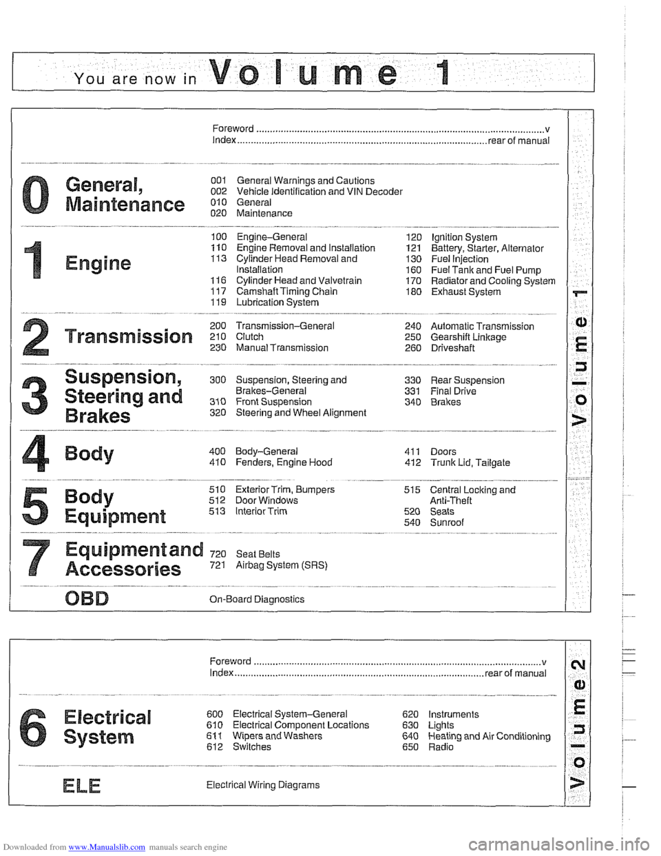
YOU are now in Volume I
I
Foreword ................... .. ........................................................................\
.......... v
Index
........................ .. ................................................................ rear of manual
General, 001 General Warnings and Cautions 002 Vehicle Identification and VIN Decoder
Maintenance OiO 020 Maintenance
Engine
100 Engine-General 110 Engine Removal and Installation
113 Cylinder Head Removal and
Installation
116 Cyiinder Head and Valvetrain 117 Camshaft Timing Chain
119 Lubrication System
200 Transmission-General
2 Transmission 210 clutch 230 ManualTransmission
I20 Ignition System
121 Battery, Starter, Alternator
130 Fuel Injection
160 Fuel Tank and Fuel Pump 170 Radiator and Cooling System
180 Exhaust System
240 Automatic Transmission
250 Gearshift Linkage 260 Driveshaft
Suspension, 300 Suspension, Steering and 330 Rear Suspension
Brakes-General 331 Final Drive
Steering and No Front Suspension 340 Brakes
320 Steering and Wheel Alignment
400 Body-General
410 Fenders, Engine Hood 411 Doors
412 Trunk Lid, Tailgate
510 Exterior Trim, Bumpers 512 Door Windows
Equipment 513 Interior Trim
7
Equipment and 720 seat Belts
Accessories 721 Airbag System (SRS)
OBD On-Board Diagnostics
. ............ ..
515 Central Lociting and
Anti-Theft
520 Seats 540 Sunroof
.................................................................... Foreword .............................. .. v
Index ................... .. ................................................................ rear of manual
Electrical
6 system
600 Electrical System-General 620 Instruments
610 Electrical Comoonent Locations 630 Liohts
611 wipers and washers 612 Switches eati in^ and Air Conditioning
Radio
. ........... ........ .........................
Electrical Wiring Diagrams
Page 28 of 1002
Downloaded from www.Manualslib.com manuals search engine
-
General
BMW special tools
Many repairs covered in this manual call for the use of BMW
special tools. Many of the BMW special tools mentioned in
this manual are simply the best thing to use to do the job cor-
rectly. In these cases, the tool is identified with a
BMW parl
number. See your authorized BMW dealer parts department
for information on how to order special tools.
There are some jobs for which expensive special tools are es-
sential, and not a cost-effective purchase for a one time repair
by the do-it-yourself owner. This manual includes such re-
pairs for the benefit of those with the necessary experience
and access to tools. For the do-it-yourselfer, the need for spe-
cial tools is noted in the text, and whether or not BMW dealer
service is recommended.
Changing a tire
- Stop car on as flat a surface as possible, in a place where you
can be easily seen by other drivers. Avoid stopping just over
the crest of a hill.
WARNING -
If a tire goes flat while driving, pull well off the road. Changing
a tire on a busy slreet or liigliway is very dangerous. If
nec-
essag drive a short distance on the flat tire to get to a safe
place. It is much better to ruin a tire or rim than to
risk being
hit.
-
- Turn on emergency flashers, and set out flares or emergency
markers well behind car.
Choclc wheel (wheel chock located
in trunk) diagonally opposite to the one being changed. Pas-
sengers should get out of car and stand well away from road.
- Take jaclc and tools from tool area beneath trunk mat. Re-
move spare tire from tire storage tray.
- Loosen wheel bolts while car is on ground, but leave them a
little snug.
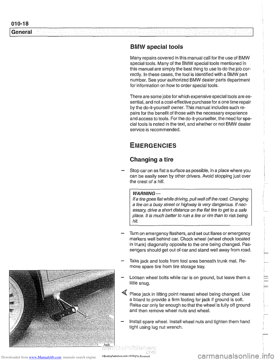
< Place jack in lifting point nearest wheel being changed. Use
a board to provide a firm footing for jack if ground is soft.
Raise car only far enough so that the wheel is fully off ground
and then remove wheel nuts and wheel.
- Install spare wheel. Install wheel nuts and tighten them hand
tight using lug nut wrench.
Page 40 of 1002
Downloaded from www.Manualslib.com manuals search engine
--- -
Maintenance
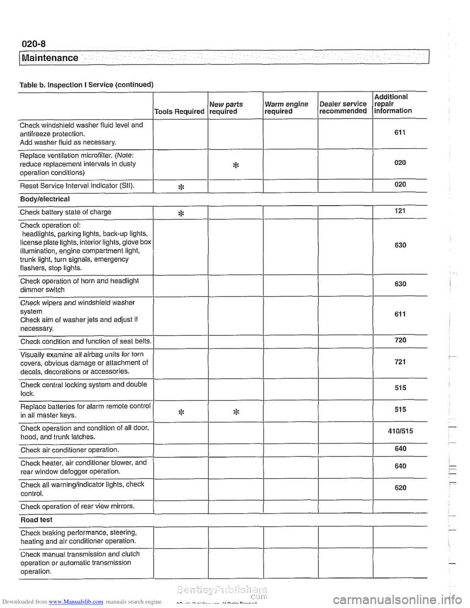
Table b. Inspection I Service (continued)
I I I I
Warm engine Dealer service
required recommended
Check windshield
washer fluid level and
antifreeze protection.
Add washer fluid as necessary.
Replace ventilation
microfilter. (Note:
reduce replacement intervals in dusty
operation conditions)
Reset Service interval Indicator
(Sil).
Additional
repair
information
Tools Required
*
eck aim of washer jets and adjust if
necessary.
covers, obvious damage or attachment o
s or accessories.
Road test
Check braking performance, steering,
heating and air conditioner operation.
Check manual transmission and clutch
operation or automatic transmission
operation. New
parts
required
*
Bodylelectrical
121
630
630
Checic battery state of charge
Check operation of:
headlights,
parking iights, back-up lights.
license plate lights, interior lights,
glove box
illumination, engine compartment light,
trunk light, turn signals, emergency
flashers, stop iights.
Check operation of horn and headlight
dimmer switch
:i:
Page 48 of 1002
Downloaded from www.Manualslib.com manuals search engine
020-1 6
Maintenance
loose, hose is damaged, or connection is dirty or corroded.
Dried coolant has achalky appearance. Hoses should be firm
and springy. Replace any hose that is cracked, has become
soft and limp, or has been contaminated by oil.
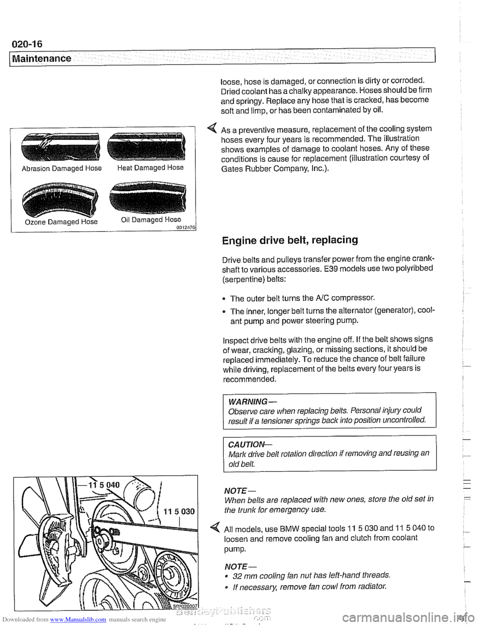
4 As a preventive measure, replacement of the cooling system
hoses every four years is recommended. The illustration
shows examples of damage to coolant hoses. Any of these
conditions is cause for replacement (illustration courtesy of
/ Abrasion Damaged Hose Heat Damaged Hose 1 Gates Rubber Company, I~c.).
Engine drive belt, replacing
Drive belts and pulleys transfer power from the engine crank-
shaft to various accessories.
E39 models use two polyribbed
(serpentine) belts:
The outer belt turns the
NC compressor.
0 The inner, longer belt turns the alternator (generator), cool-
ant pump and power steering pump.
Inspect drive belts with the engine off. If the belt shows signs
of wear, cracking, glazing, or missing sections, it should be
replaced
immediately. To reduce the chance of belt failure
while driving, replacement of the belts every four years is
recommended.
WARNING -
Observe care when replacing belts. Personal injury could
result if a tensioner springs back into position uncontrolled.
CA UTIOI\C
Mark drive belt rotation direction if removing and reusing an
old belt.
NOTE-
When belts are replaced with new ones, store the old set in
the trunk for emergency use.
All models, use
BMW special tools 11 5 030 and 11 5 040 to
loosen and remove cooling fan and clutch from coolant
pump.
NOTE-
32 mm cooling fan nut has left-hand threads
If necessary, remove fan cowl from radiator.
Page 55 of 1002
Downloaded from www.Manualslib.com manuals search engine
Maintenance
- To remove battery corrosion:
Disconnect battery cables. Disconnect negative (-)cable
first.
* Remove battery from trunk
Clean terminal posts and cable clamps with a wire brush.
Clean main chassis ground terminal next to battery.
Corrosion can be washed away with a
baking soda and
water solution that will neutralize acid.
Reinstall battery and reconnect cable clamps, positive
(+)
cable first.
Lightly coat outside of terminals, hold down screws, and
clamps with petroleum jelly, grease, or a commercial
battery terminal corrosion inhibitor.
WARNING
-
Battery acid is extremely dangerous. Take care to keep it
from contacting eyes, skin, or clothing. Wear eye protection.
Extinguish all
smolihg materials and do not work near any
oaen flames.
CAUTION-
Prior to disconnecting the batteg read the battery discon-
nection cautions given in
001 General Cautions and
Warnings.
NOTE-
The original equipment battery in E39 models is mainte-
nance free. The original electrolyte will normally last the
entire service life of the battery under moderate climate con-
ditions.
Battery electrolyte should be maintained at the correct level
just above the battery plates and theirseparators. The correct
level is approximately
5 mm ('14 in.) above the top of battery
plates or to the top of the indicator
marks (if applicable). The
battery plates and the indicator marks can be seen once the
fillercaps are removed.
if theelectrolyte level is low, replenish
it by adding distilled water only.
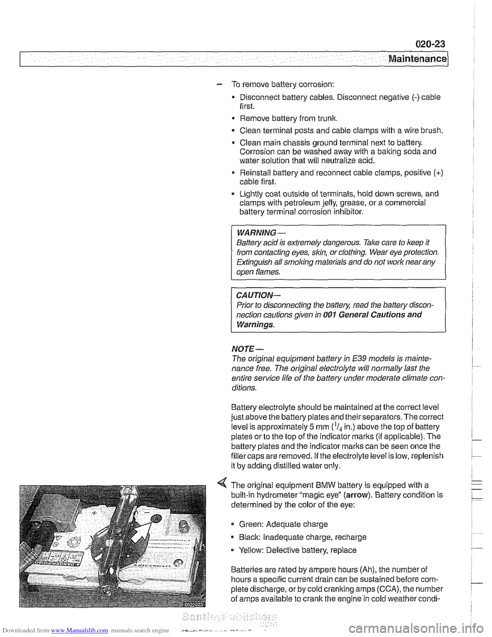
4 The original equipment BMW battery is equipped with a
built-in hydrometer "magic eye"
(arrow). Battery condition is
determined by the color of the eye:
Green: Adequate charge
* Black: Inadequate charge, recharge
Yellow: Defective battery, replace
Batteries are rated by ampere hours (Ah), the number of
hours a specific current drain can be sustained before com-
plete discharge, or by cold cranking amps (CCA), the number
of amps available to crank the engine in cold weather
condi-
Page 369 of 1002
Downloaded from www.Manualslib.com manuals search engine
Battery, Starter, ~lternatorl
@ TO fuse & relay panel Battery Safety Terminal
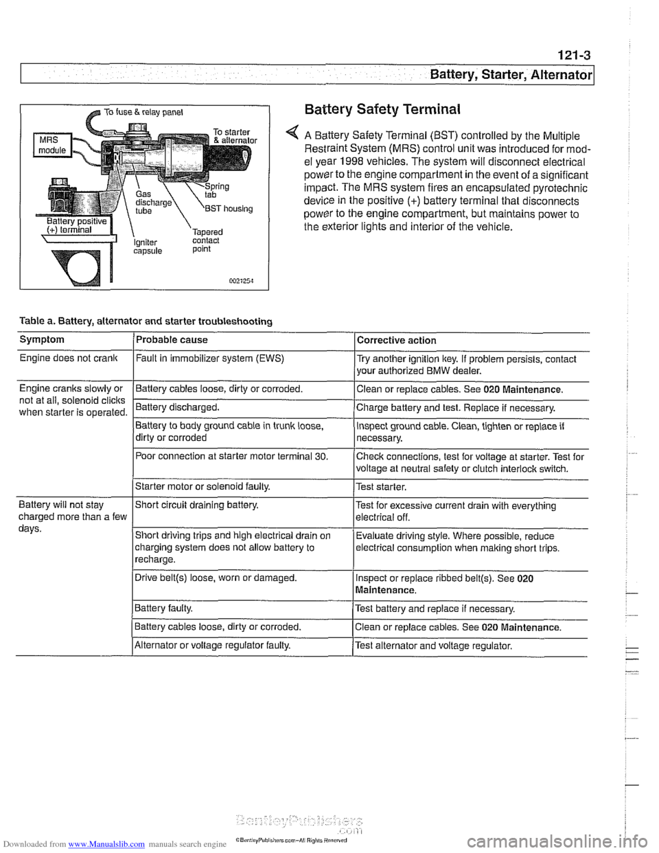
A Battery Safety Terminal (BST) controlled by the Multiple
Restraint System (MRS) control unit was introduced for mod-
el year 1998
vehicles. The system will disconnect electrical
power to the engine compartment
in the event of a significant
impact. The MRS system fires an encapsulated pyrotechnic
device
in the positive (+) battery terminal that disconnects
power to the engine compartment, but maintains power to
the exterior lights and interior of the vehicle.
point
002125~1
Table a. Battery, alternator and starter troubleshooting
1-
/Starter motor or solenoid faulty. l~est starter.
Symptom
Engine does not crank
Engine cranks slowly or
not at all, solenoid
clicits
when starter is operated.
I I
Battery will not stay IShort circuit draining battery. l~est for excessive current drain with everything
Probable cause
Fault
in immobilizer system (EWS)
-Clean Battery cables loose, dirty or corroded.
Battery discharged.
Battery to body ground cable in trunk
loose,
dirty or corroded
Poor connection at starter motor terminal
30.
Corrective action
Try another ignition key. If problem persists, contact
your authorized BMW dealer.
or replace cables. See 020
~aintenance.
Charge battery and test. Replace if necessary.
inspect ground cable. Clean, tighten or replace if
necessary.
Checlc connections, test for voltage at starter. Test for
voltage at neutral safety or clutch
interloclc switch.
charged more than a few
days.
I~atter~ faulty. /Test battery and replace if necessary.
Short driving trips and high electrical drain
on
charging system does not allow battery to
recharge.
. I
I Battery cables loose, dirty or corroded. Iclean or replace cables. See 020 Maintenance.
Evaluate driving
style. Where possible, reduce
electrical
consumption when malting short trips.
Drive
belt@) loose, worn or damaged.
IAlternator or voltage regulator faulty. /Test alternator and voltage regulator.
Inspect
or replace ribbed
belt@). See 020
Maintenance.
Page 373 of 1002
Downloaded from www.Manualslib.com manuals search engine
Battery, Starter, ~lternatorl
WARNING-
Always wear protective goggles and clothing when perform-
ing a load test.
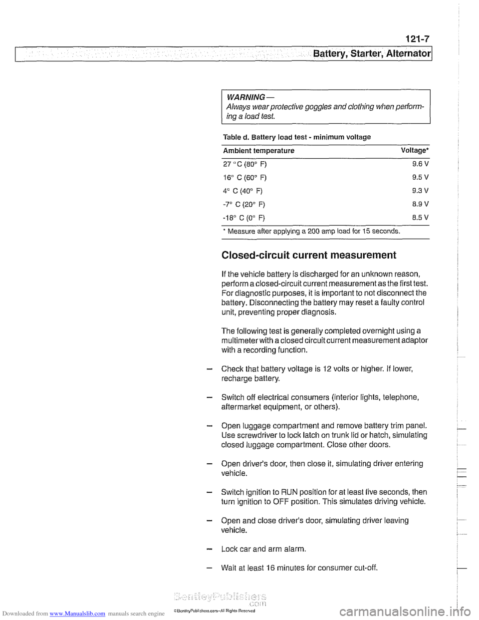
Table
d. Battery load test - minimum voltage
Ambient temperature Voltage*
27
" C (80" F) 9.6 V
-I 8' C (0"
F) 8.5 V
* Measure
after applying a 200 amp load for 15 seconds.
Closed-circuit current measurement
If the vehicle battery is discharged for an unknown reason,
perform a closed-circuit current measurement as the first test.
For diagnostic purposes, it is important to not disconnect the
battery. Disconnecting the battery may reset a faulty control
unit, preventing proper diagnosis.
The following test is generally completed overnight using a
multimeterwith a closed circuitcurrent measurement adaptor
with a recording function
- Check that battery voltage is 12 volts or higher. If lower,
recharge battery.
- Switch off electrical consumers (interior lights, telephone,
aftermarket equipment, or others).
- Open luggage compartment and remove battery trim panel.
Use screwdriver to lock latch on trunk lid or hatch, simulating
closed luggage compartment. Close other doors.
- Open driver's door, then close it, simulating driver entering
vehicle.
- Switch ignition to RUN position for at least five seconds, then
turn ignition to OFF position. This simulates driving vehicle.
- Open and close driver's door, simulating driver leaving
vehicle.
- Lock car and arm alarm.
- Wait at least 16 minutes for consumer cut-off.
Page 375 of 1002
Downloaded from www.Manualslib.com manuals search engine
121-9
Battery, Starter, ~lternatorl
Battery charging
Discharged batteries can be recharged using a batterycharg-
er. Remove the battery from the trunk during charging.
Prolonged charging causes electrolyte evaporation to a level
that can damage the battery. It is best to use a low-current
charger
(6 amperes or less) to prevent battery damage
caused by overheating.
WARNING -
Hydrogen gas given off by the battery during charging is ex-
plosive. Do not smoke.
Keep open flames away from the top
ofthe batte~ and prevent electrical sparks by turning off the
battery charger before connecting or disconnecting it.
Battery electrolyte (sulfuric acid) can damage the car. If
electrolyte is spilled, clean the area with a solution
ofbak-
ing soda and water.
Always allow a frozen battery to thaw before attempting
to recharge it.
Always disconnect both battery cables and remove bat-
tery from vehicle during battery charging. Do not ex-
ceed
16.5 charging voltage at the battery
Battery safety terminal, replacing
If the battery safety terminal has been triggered, investigate
and correct the cause prior to replacement.
- Working in right side of luggage compartment, remove bat-
tery trim panel.
- Disconnect negative (-) battery terminal and cover with
insulator.
- Disconnect positive (+) cable from battery.
- Release positive (+) cable from cable brackets on luggage
compartment wall. Lay new repair cable parallel to positive
cable.
- Mark off length of new cable on old cable. Allow 10 cm
(2.5 in) of slack.
- Saw through old cable.
Do not use bolt cutters or similar tools to cut through cable.
A cable end that has been squashed
flat will not fit into the
Page 634 of 1002
Downloaded from www.Manualslib.com manuals search engine
300-1 4
I Susoension. Steerina and Brakes - General
DSC system I
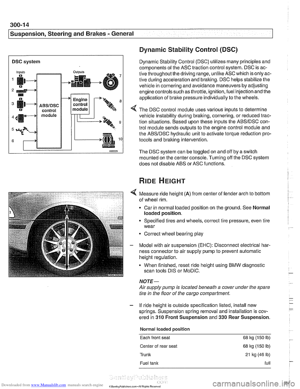
Dynamic Stability Control (DSC)
Dynamic Stability Control (DSC) utilizes many principles and
components of the ASC traction control system. DSC is ac-
tive throughoutthe driving range, unlike ASC which is only ac-
tive during acceleration and braking. DSC helps stabilize the
vehicle in cornering and avoidance maneuvers by adjusting
engine controls such as throttle, ignition, fuel injection and the
application of
brake pressure individually to the wheels.
Inputs
fi- 0
2 4-* .. o
[11-' IJ
411m4
3?-
G
4 The DSC control module uses various inputs to determine
vehicle instability during braking, cornering, or reduced trac-
tion situations. Based upon these inputs the ABSIDSC con-
trol module sends outputs to the engine control module and
the ABSIDSC hydraulic unit to activate torque reduction pro-
tocols and braking intervention.
-
ABSIDSC control module
OUI~YIS
4
The DSC system can be toggled on and off by a switch
mounted on the center console. Turning off the DSC system
does not disable ABS or ASC functions.
+
Measure ride height (A) from center of fender arch to bottom
of wheel rim.
Car in normal loaded position on the ground. See Normal
loaded position.
Engine
control
module
Specified tires and wheels, correct tire pressure, even tire
wear
-'* 9-
.%A
Correct wheel bearing play
T'== ..t, 9 B
-.m
Model with air suspension (EHC): Disconnect electrical har-
ness connector to air supply pump to prevent automatic
height regulation.
When finished, reset ride height using BMW diagnostic
scan tools DIS or
MoDiC.
NOTE-
Airsupply pump is located beneath a cover under the spare
tire in the floor of the cargo compartment.
- If ride height is outside specification listed, install new
springs. Suspension spring removal and installation is cov-
ered in
310 Front Suspension and 330 Rear Suspension.
Normal loaded position
Each front seat 68 kg (150 Ib)
Center of rear seat 68 kg (150 lb)
Trunk 21 kg (46 lb)
Fuel tank full
Page 701 of 1002
Downloaded from www.Manualslib.com manuals search engine
330-5
Rear Suspension
REAR STRUTS AND SPRINGS
(SEDAN MODELS)
Rear strut assembly, removing and
installing
Replace struts and coil springs in pairs only.
- Raise car and remove rear wheels.
WARNING -
Male sure the car is firmly supported on jack stands de-
signed for the purpose. Place jack stands underneath struc-
tural chassis points. Do not place jack stands under
suspension parts.
- Remove rear parcel shelf:
Remove rear seat headrests by pulling straight up.
Remove both rear roof pillar (C-pillar) trim panels.
Unbolt rear seat
belt anchors. See 720 Seat Belts.
Models with fixed rear seat: Remove rear seat backrest.
See 520 Seats.
* Models with fold-down rear seat: Remove rear seat back-
rest side sections. See 520 Seats. Fold down backrest.
* Working inside trunk, remove roller blind mounting nuts
and bolts, if applicable. Also disconnect roller blind har-
ness connector at right edge of rear seat backrest.
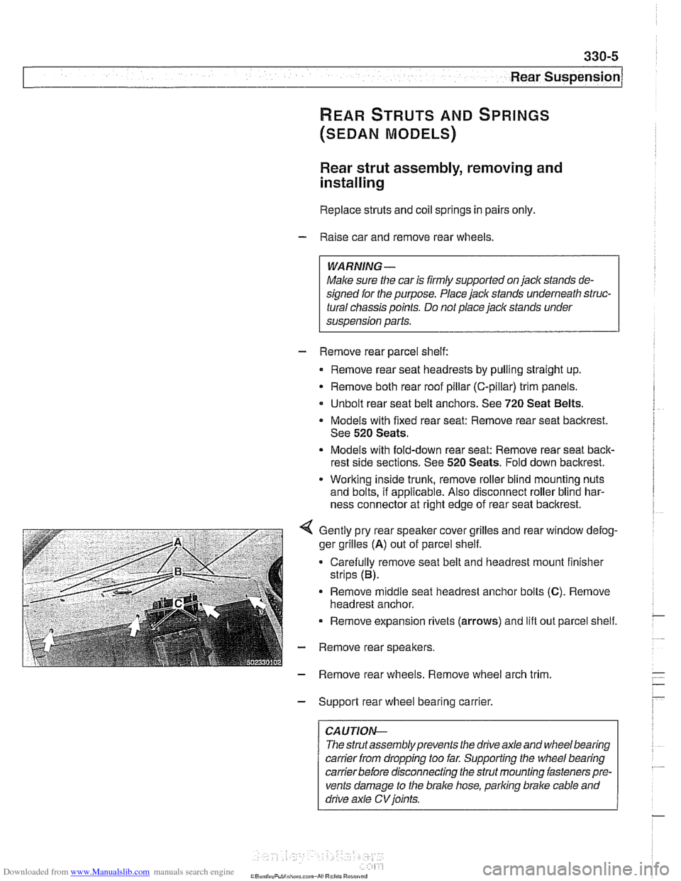
Gently pry rear speaker cover grilles and rear window defog-
ger grilles
(A) out of parcel shelf.
Carefully remove seat belt and headrest mount finisher
strips (B).
Remove
middle seat headrest anchor bolts (C). Remove
headrest anchor.
Remove expansion rivets (arrows) and lift out parcel shelf.
- Remove rear speakers.
- Remove rear wheels. Remove wheel arch trim
- Support rear wheel bearing carrier.
CAUTION-
The strutassembly prevents the drive axle and wheel bearing
carrier
from dropping too far. Supporting the wheel bearing
carrierbefore disconnecting the strut mounting fasteners pre-
vents damage to the brake hose, parking brake cable and
drive axle
CV joints.