M62 BMW 540i 2001 E39 M62TU Engine Workshop Manual
[x] Cancel search | Manufacturer: BMW, Model Year: 2001, Model line: 540i, Model: BMW 540i 2001 E39Pages: 37, PDF Size: 3.9 MB
Page 2 of 37
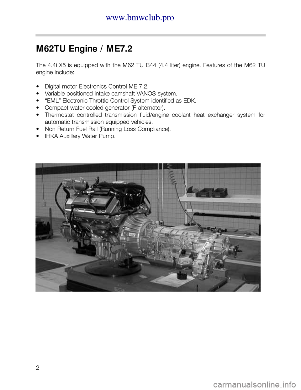
with the M62 TU B44 (4.4 liter) engine. Features of the M62 TU
Page 3 of 37
3
M62 TU VANOS
OVERVIEW
The variable intake valve timing system on the M62 TU continues to be identified as
VANOS. This acronym comes from the German words; V
Ariable NOckenwellen Steuerung,
which means Variable Camshaft Control.
The M62 TU VANOS system is a new variant providing stepless VANOS functionality on
each intake camshaft. The system is continuously variable within its range of adjustment
providing optimized camshaft positioning for all engine operating conditions.
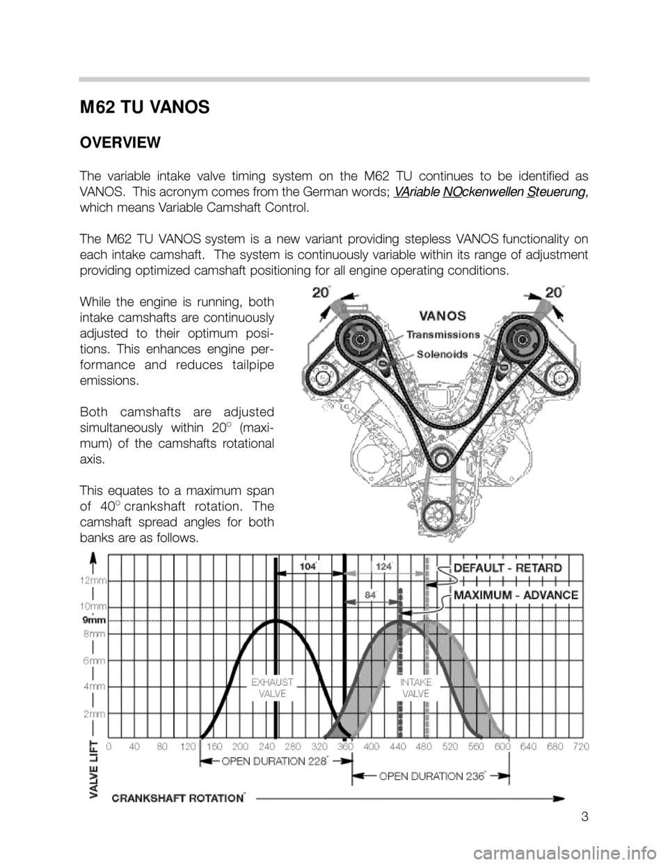
While the engine is running, both
intake camshafts are continuously
adjusted to their optimum posi-
tions. This enhances engine per-
formance and reduces tailpipe
emissions.
Both camshafts are adjusted
simultaneously within 20
O(maxi-
mum) of the camshafts rotational
axis.
This equates to a maximum span
of 40
Ocrankshaft rotation. The
camshaft spread angles for both
banks are as follows.
Page 5 of 37
5
BASIC FUNCTION OF BMW VANOS SYSTEMS
All BMW VANOS systems are operated through electric/hydraulic/mechanical control.
Electric Control: The engine control module is responsible for activating a VANOS sole-
noid valve based on DME program mapping. The activation parameters are influenced
by the following input signals:
• Engine speed
• Load (intake air mass)
• Engine temperature
• Camshaft position
• Oil temperature (MS 42.0 only)
Depending on the specific VANOS system, the solenoid valve is one of two types:
• Basic black/white (on/off) solenoid valve. Found on M50 TU and M52 engines.
• Variable position solenoid valve. Found on the M52 TU and M62 TU engines.
Hydraulic Control:The position of the solenoid valve directs the hydraulic flow of engine
oil. The controlled oil flow acts on the mechanical components of VANOS system to
position the camshaft.
Mechanical Control: The mechanical components of all VANOS systems operate under
the same principle. The controlled hydraulic engine oil flow is directed through advance
or retard activation oil ports. Each port exits into a sealed chamber on the opposite sides
of a control piston.
• The control piston on six cylinder engine systems (M50TU, M52 & M52TU) is con-
nected to a separate helical gear cup.
• The control piston on the M62TU VANOS system incorporates the helical gear.
In its default position the oil flow is directed to the rear surface of the piston. This pulls
the helical gear forward and maintains the retarded valve timing position.
When the oil flow is directed to the front surface of the piston, the oil pushesthe helical
gear in the opposite direction which rotates the matched helical gearing connected to the
camshaft.
The angled teeth of the helical gears cause thepushingmovement to be converted into
arotationalmovement. The rotational movement is added to the turning of the
camshaft providing the variable camshaft positioning.
Page 7 of 37
7
M62 TU VANOS COMPONENTS
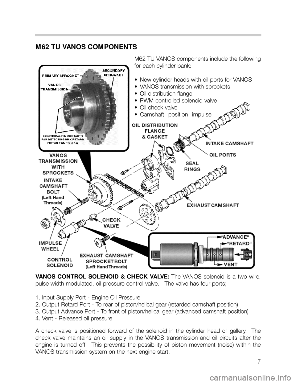
M62 TU VANOS components include the following
for each cylinder bank:
•New cylinder heads with oil ports for VANOS
•VANOS transmission with sprockets
•Oil distribution flange
•PWM controlled solenoid valve
•Oil check valve
•Camshaft position impulse
VANOS CONTROL SOLENOID & CHECK VALVE:The VANOS solenoid is a two wire,
pulse width modulated, oil pressure control valve. The valve has four ports;
1. Input Supply Port - Engine Oil Pressure
2. Output Retard Port - To rear of piston/helical gear (retarded camshaft position)
3. Output Advance Port - To front of piston/helical gear (advanced camshaft position)
4. Vent - Released oil pressure
A check valve is positioned forward of the solenoid in the cylinder head oil gallery. The
check valve maintains an oil supply in the VANOS transmission and oil circuits after the
engine is turned off. This prevents the possibility of piston movement (noise) within the
VANOS transmission system on the next engine start.
Page 9 of 37
9
M62 TU VANOS CONTROL
As the engine camshafts are rotated by the primary and secondary timing chains, the
ME7.2 control module activates the VANOS solenoids via a PWM (pulse width modulated)
ground signal based on a program map. The program is influenced by engine speed, load,
and engine temperature.
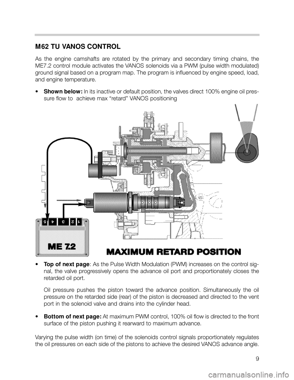
•Shown below: In its inactive or default position, the valves direct 100% engine oil pres-
sure flow to achieve max “retard” VANOS positioning
•Top of next page: As the Pulse Width Modulation (PWM) increases on the control sig-
nal, the valve progressively opens the advance oil port and proportionately closes the
retarded oil port.
Oil pressure pushes the piston toward the advance position. Simultaneously the oil
pressure on the retarded side (rear) of the piston is decreased and directed to the vent
port in the solenoid valve and drains into the cylinder head.
•Bottom of next page: At maximum PWM control, 100% oil flow is directed to the front
surface of the piston pushing it rearward to maximum advance.
Varying the pulse width (on time) of the solenoids control signals proportionately regulates
the oil pressures on each side of the pistons to achieve the desired VANOS advance angle.
Page 11 of 37
11
VANOS SERVICE NOTES
VALVE TIMING PROCEDURES
Refer to TIS for complete Valve Timing Procedures.M62 TU valve timing adjustment is sim-
ilar to the previous non VANOS M62 engine with the exceptionof setting the VANOS
transmissions to their max retard positions with an ohmmeter and attaching the camshaft
gears to each camshaft with single reverse threaded bolts.
• After locking the crankshaft at TDC, the camshaft alignment tools (P/N 90 88 6 112 440)
are placed on the square blocks on the rear of the camshafts locking them in place.
• The exhaust camshaft sprockets and VANOS transmission units with timing chains are
placed onto their respective camshafts.
• The exhaust camshaft sprockets and VANOS transmissions are secured to the
camshafts with their respective single, reverse threaded bolt. Finger tighten only at this
point. Install the chain tensioner into the timing chain case and tension the chain.
• Connect an ohmmeter across two of the three pin contacts on the front edge of one of
the VANOS transmissions. Twist the inner hub of transmission to the left (counter clock-
wise). Make sure the ohmmeter indicates closed circuit. This verifies that the trans-
mission in the default max retard position.
• Using an open end wrench on the camshaft to hold it in place, torque the VANOS trans-
mission center bolt to specification.
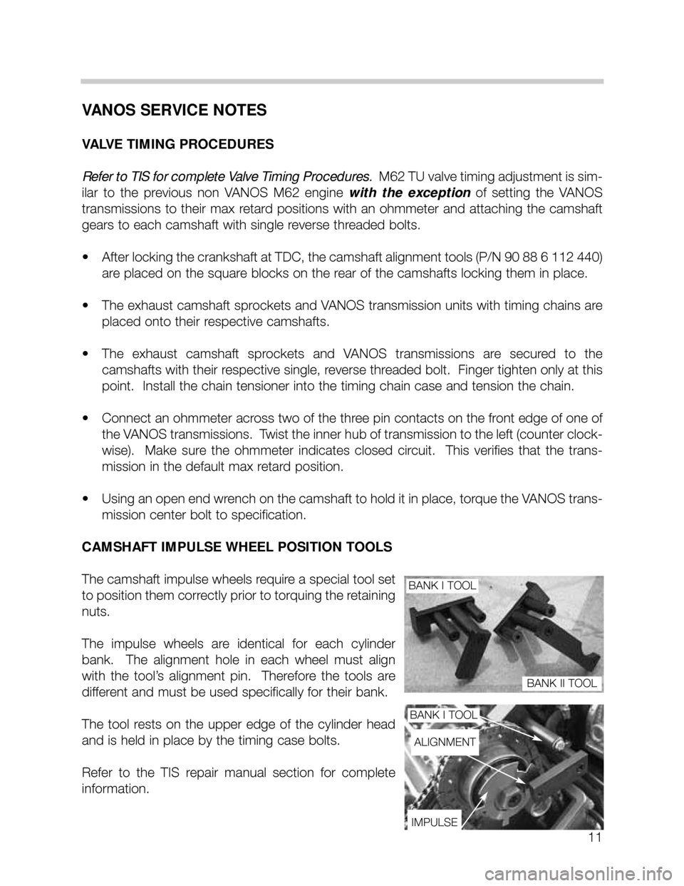
CAMSHAFT IMPULSE WHEEL POSITION TOOLS
The camshaft impulse wheels require a special tool set
to position them correctly prior to torquing the retaining
nuts.
The impulse wheels are identical for each cylinder
bank. The alignment hole in each wheel must align
with the tool’s alignment pin. Therefore the tools are
different and must be used specifically for their bank.
The tool rests on the upper edge of the cylinder head
and is held in place by the timing case bolts.
Refer to the TIS repair manual section for complete
information.
BANK I TOOL
BANK I TOOL
BANK II TOOL
ALIGNMENT
IMPULSE
Page 20 of 37
20
HOT FILM AIR MASS SENSOR (HFM 5)
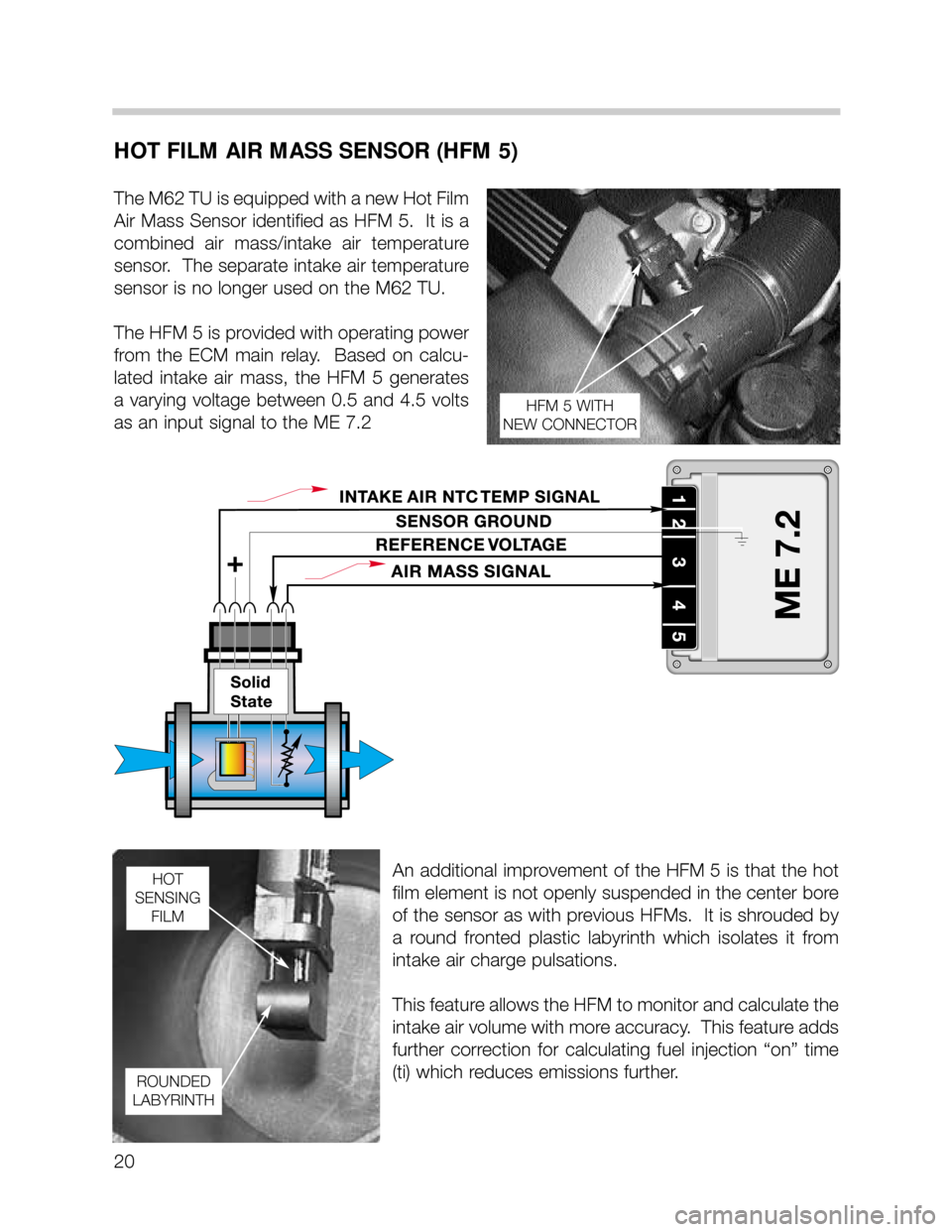
The M62 TU is equipped with a new Hot Film
Air Mass Sensor identified as HFM 5. It is a
combined air mass/intake air temperature
sensor. The separate intake air temperature
sensor is no longer used on the M62 TU.
The HFM 5 is provided with operating power
from the ECM main relay. Based on calcu-
lated intake air mass, the HFM 5 generates
a varying voltage between 0.5 and 4.5 volts
as an input signal to the ME 7.2
An additional improvement of the HFM 5 is that the hot
film element is not openly suspended in the center bore
of the sensor as with previous HFMs. It is shrouded by
a round fronted plastic labyrinth which isolates it from
intake air charge pulsations.
This feature allows the HFM to monitor and calculate the
intake air volume with more accuracy. This feature adds
further correction for calculating fuel injection “on” time
(ti) which reduces emissions further.
HFM 5 WITH
NEW CONNECTOR
HOT
SENSING
FILM
ROUNDED
LABYRINTH
Page 30 of 37
30
ELECTRIC THROTTLE VALVE (EDK) CONTROL
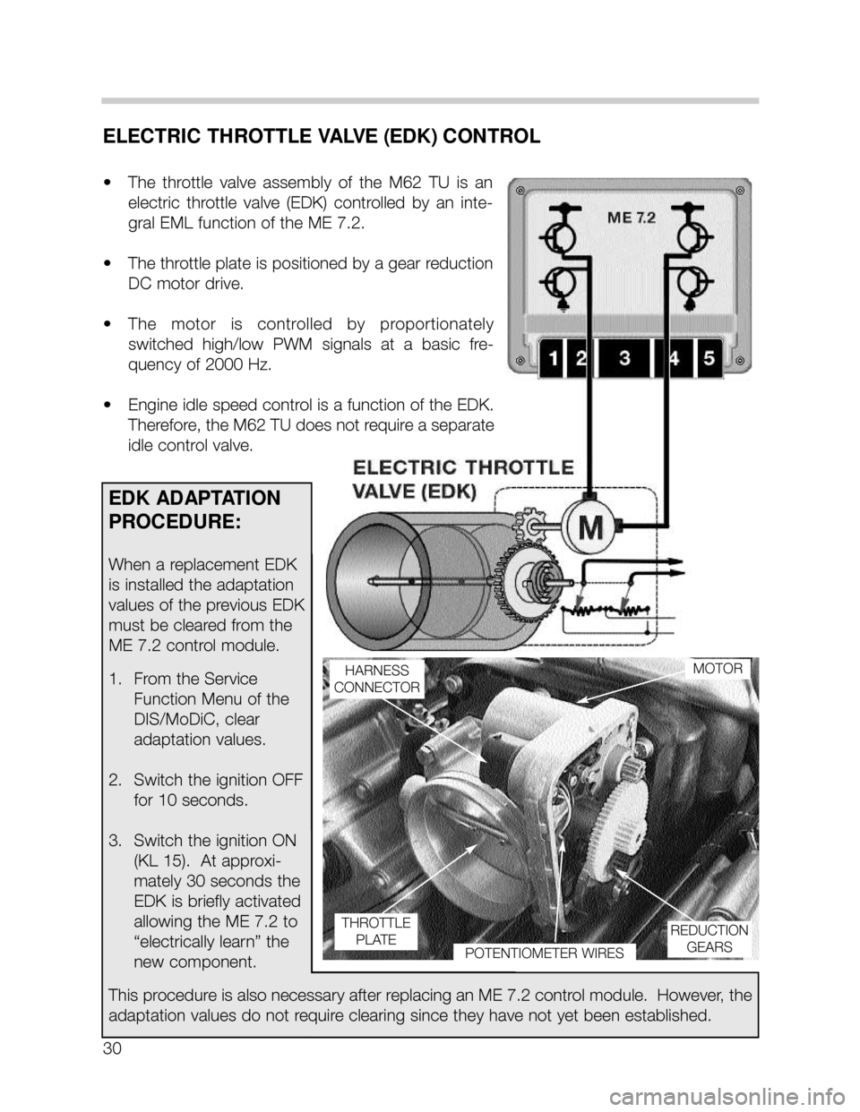
• The throttle valve assembly of the M62 TU is an
electric throttle valve (EDK) controlled by an inte-
gral EML function of the ME 7.2.
• The throttle plate is positioned by a gear reduction
DC motor drive.
• The motor is controlled by proportionately
switched high/low PWM signals at a basic fre-
quency of 2000 Hz.
• Engine idle speed control is a function of the EDK.
Therefore, the M62 TU does not require a separate
idle control valve.
HARNESS
CONNECTORMOTOR
REDUCTION
GEARS
POTENTIOMETER WIRES
THROTTLE
PLATE
EDK ADAPTATION
PROCEDURE:
When a replacement EDK
is installed the adaptation
values of the previous EDK
must be cleared from the
ME 7.2 control module.
1. From the Service
Function Menu of the
DIS/MoDiC, clear
adaptation values.
2. Switch the ignition OFF
for 10 seconds.
3. Switch the ignition ON
(KL 15). At approxi-
mately 30 seconds the
EDK is briefly activated
allowing the ME 7.2 to
“electrically learn” the
new component.
This procedure is also necessary after replacing an ME 7.2 control module. However, the
adaptation values do not require clearing since they have not yet been established.