520 BMW 540i 2001 E39 Workshop Manual
[x] Cancel search | Manufacturer: BMW, Model Year: 2001, Model line: 540i, Model: BMW 540i 2001 E39Pages: 1002
Page 3 of 1002

Downloaded from www.Manualslib.com manuals search engine
YOU are now in Volume I
I
Foreword ................... .. ........................................................................\
.......... v
Index
........................ .. ................................................................ rear of manual
General, 001 General Warnings and Cautions 002 Vehicle Identification and VIN Decoder
Maintenance OiO 020 Maintenance
Engine
100 Engine-General 110 Engine Removal and Installation
113 Cylinder Head Removal and
Installation
116 Cyiinder Head and Valvetrain 117 Camshaft Timing Chain
119 Lubrication System
200 Transmission-General
2 Transmission 210 clutch 230 ManualTransmission
I20 Ignition System
121 Battery, Starter, Alternator
130 Fuel Injection
160 Fuel Tank and Fuel Pump 170 Radiator and Cooling System
180 Exhaust System
240 Automatic Transmission
250 Gearshift Linkage 260 Driveshaft
Suspension, 300 Suspension, Steering and 330 Rear Suspension
Brakes-General 331 Final Drive
Steering and No Front Suspension 340 Brakes
320 Steering and Wheel Alignment
400 Body-General
410 Fenders, Engine Hood 411 Doors
412 Trunk Lid, Tailgate
510 Exterior Trim, Bumpers 512 Door Windows
Equipment 513 Interior Trim
7
Equipment and 720 seat Belts
Accessories 721 Airbag System (SRS)
OBD On-Board Diagnostics
. ............ ..
515 Central Lociting and
Anti-Theft
520 Seats 540 Sunroof
.................................................................... Foreword .............................. .. v
Index ................... .. ................................................................ rear of manual
Electrical
6 system
600 Electrical System-General 620 Instruments
610 Electrical Comoonent Locations 630 Liohts
611 wipers and washers 612 Switches eati in^ and Air Conditioning
Radio
. ........... ........ .........................
Electrical Wiring Diagrams
Page 271 of 1002
Downloaded from www.Manualslib.com manuals search engine
Camshaft Timing Chain
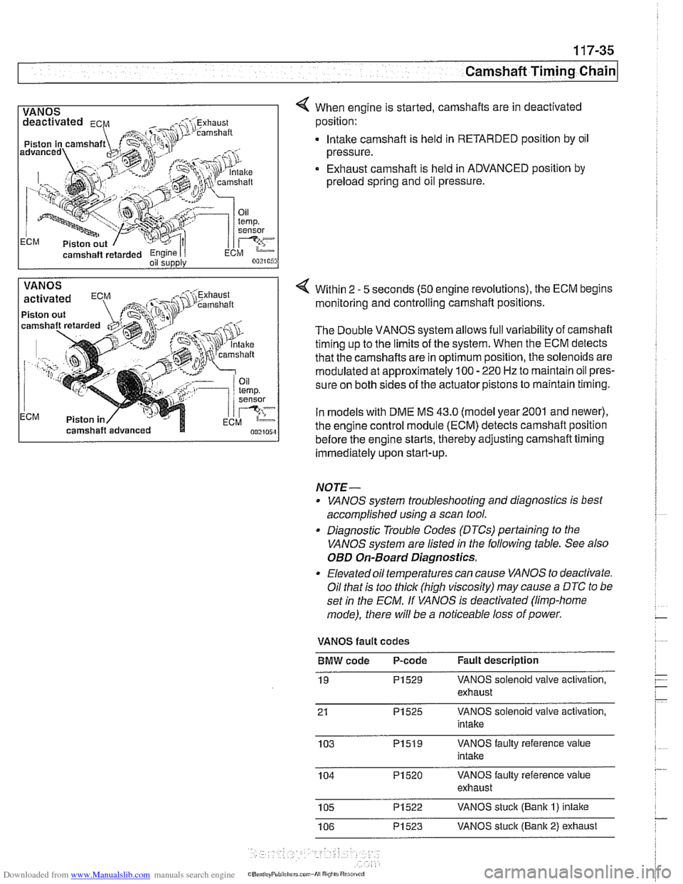
1 VANOS I 4 When engine is started, camshafts are in deactivated
camshaft
retarded Engine I i oil supply
position:
. lntalte camshaft is held in RETARDED position by oil
pressure.
Exhaust camshaft is held in ADVANCED position by
preload spring and oil pressure.
VANOS
Piston out
ECM Piston in Within 2
- 5
seconds (50 engine revolutions), the ECM begins
monitoring and controlling camshaft positions.
The Double VANOS system allows full variability of camshaft
timing up to the limits of the system. When the ECM detects
that the camshafts are in optimum position, the solenoids are
modulated at approximately 100
- 220 Hz to maintain oil pres-
sure on both sides of the actuator pistons to maintain timing.
In models with DME
MS 43.0 (model year2001 and newer),
the engine control module (ECM) detects camshaft position
before the engine starts, thereby adjusting camshaft timing
immediately upon start-up.
NOTE-
. VANOS system troubleshooting and diagnostics is best
accomplished using a scan tool.
. Diagnostic Trouble Codes (DTCs) pertaining to the
VANOS system are listed
in the following table. See also
OED On-Board Diagnostics.
Elevated oil temperatures can cause VANOS to deactivate.
Oil that is too thick (high viscosity) may cause
a DTC to be
set
in the ECM. If VANOS is deactivated (limp-home
mode), there will be a noticeable loss of power.
VANOS fault codes
BMW code P-code Fault description
19
PI529 VANOS solenoid valve activation,
exhaust
21
PI525 VANOS solenoid valve activation,
intake
103
PI519 VANOS faulty reference value
intake
104
PI520 VANOS faulty reference value
exhaust
105
PI522 VANOS stuck (Bank I) intake
106
PI523 VANOS stuck (Bank 2) exhaust
Page 576 of 1002
Downloaded from www.Manualslib.com manuals search engine
230-12
/ Manual Transmission
Output shaft seal, replacing (6-speed
transmission) (transmission installed)
- Raise and safely support vehicle.
WARNING-
Make sure the car is stable and well supported at all times.
Use a professional automotive lift
orjack stands designed for
the purpose.
A floorjack is not adequate support.
- Remove exhaust system and heat shields. See 180 Exhaust
System.
- Support transmission with transmission jack
- Disconnect driveshaft at transmission output flange, and
hang driveshaft to side. See
260 Driveshaft.
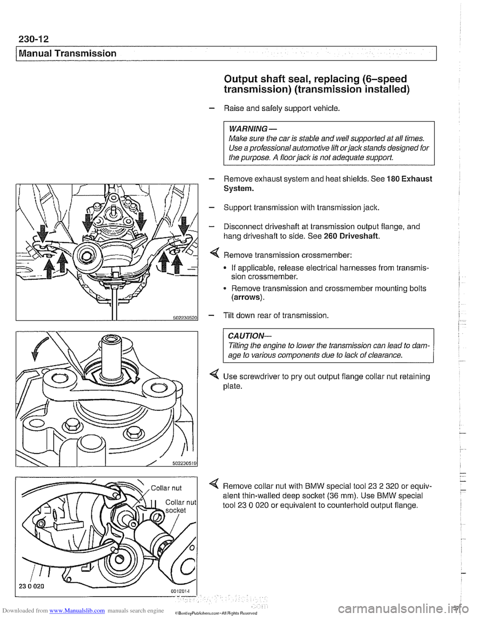
Remove transmission crassmember:
If applicable, release electrical harnesses from transmis-
sion crossmember.
Remove transmission and crossmember mounting bolts
(arrows).
5022305201 - Tilt down rear of transmission
CAUTION-
Tlting the engine to lower the transmission can lead to dam-
age to various components due to lack of clearance.
Use screwdriver to pry out output flange collar nut retaining
plate.
Remove collar nut with BMW special tool
23 2 320 or equiv-
alent thin-walled deep socltet
(36 mm). Use BMW special
tool
23 0 020 or equivalent to counterhold output flange.
Page 701 of 1002
Downloaded from www.Manualslib.com manuals search engine
330-5
Rear Suspension
REAR STRUTS AND SPRINGS
(SEDAN MODELS)
Rear strut assembly, removing and
installing
Replace struts and coil springs in pairs only.
- Raise car and remove rear wheels.
WARNING -
Male sure the car is firmly supported on jack stands de-
signed for the purpose. Place jack stands underneath struc-
tural chassis points. Do not place jack stands under
suspension parts.
- Remove rear parcel shelf:
Remove rear seat headrests by pulling straight up.
Remove both rear roof pillar (C-pillar) trim panels.
Unbolt rear seat
belt anchors. See 720 Seat Belts.
Models with fixed rear seat: Remove rear seat backrest.
See 520 Seats.
* Models with fold-down rear seat: Remove rear seat back-
rest side sections. See 520 Seats. Fold down backrest.
* Working inside trunk, remove roller blind mounting nuts
and bolts, if applicable. Also disconnect roller blind har-
ness connector at right edge of rear seat backrest.
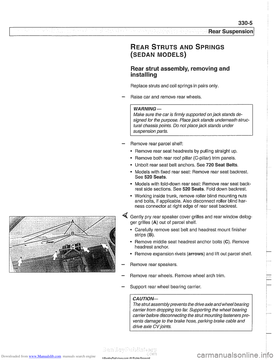
Gently pry rear speaker cover grilles and rear window defog-
ger grilles
(A) out of parcel shelf.
Carefully remove seat belt and headrest mount finisher
strips (B).
Remove
middle seat headrest anchor bolts (C). Remove
headrest anchor.
Remove expansion rivets (arrows) and lift out parcel shelf.
- Remove rear speakers.
- Remove rear wheels. Remove wheel arch trim
- Support rear wheel bearing carrier.
CAUTION-
The strutassembly prevents the drive axle and wheel bearing
carrier
from dropping too far. Supporting the wheel bearing
carrierbefore disconnecting the strut mounting fasteners pre-
vents damage to the brake hose, parking brake cable and
drive axle
CV joints.
Page 789 of 1002
Downloaded from www.Manualslib.com manuals search engine
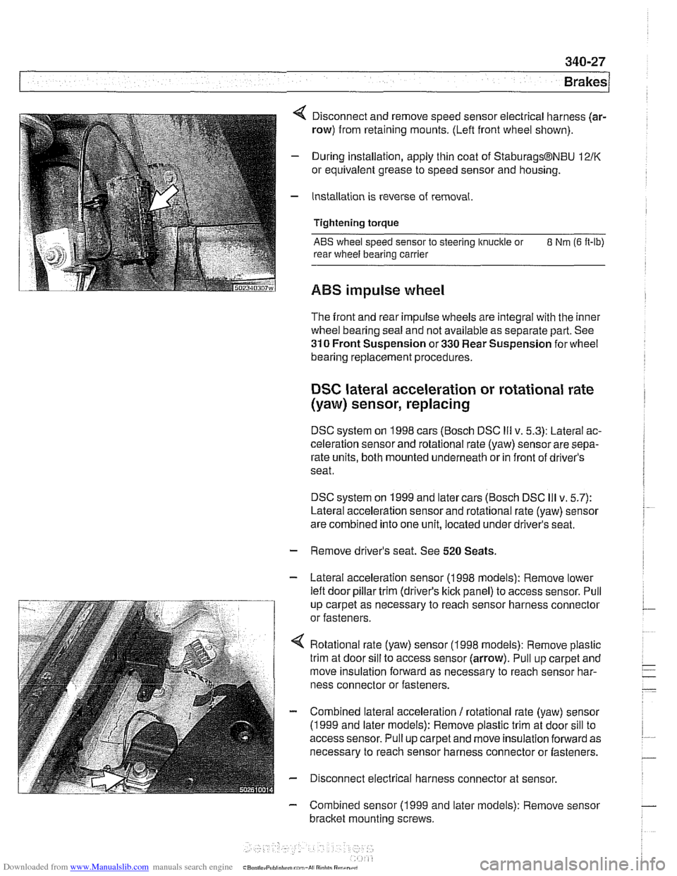
4 Disconnect and remove speed sensor electrical harness (ar-
row) from retaining mounts. (Lefl front wheel shown).
- During installation, apply thin coat of StaburagsBNBU 12/K
or equivalent grease to speed sensor and housing.
- Installation is reverse of removal.
Tightening torque
ABS wheel speed sensor to steering knuckle or 8 Nm (6 It-lb)
rear wheel bearing carrier
ABS impulse wheel
The front and rear impulse wheels are integral with the inner
wheel bearing seal and not available as separate part. See
310 Front Suspension or 330 Rear Suspension for wheel
bearing replacement procedures.
DSC lateral acceleration or rotational rate
(yaw) sensor, replacing
DSC system on 1998 cars (Bosch DSC Ill v. 5.3): Lateral ac-
celeration sensor and rotational rate (yaw) sensor are sepa-
rate units, both mounted underneath or in front of driver's
seat.
DSC system on 1999 and later cars (Bosch DSC
Ill v. 5.7):
Lateral acceleration sensor and rotational rate (yaw) sensor
are combined into one unit, located under driver's seat.
- Remove driver's seat. See 520 Seats.
- Lateral acceleration sensor (1 998 models): Remove lower
lefl door pillar trim (driver's
kick panel) to access sensor. Pull
up carpet as necessary to reach sensor harness connector
or fasteners.
4 Rotational rate (yaw) sensor (1998 models): Remove plastic
trim at door sill to access sensor (arrow). Pull up carpet and
move insulation forward as necessary to reach sensor har-
ness connector or fasteners.
- Combined lateral acceleration / rotational rate (yaw) sensor
(1 999 and later models): Remove plastic trim at door sill to
access sensor. Pull up carpet and move insulation forward as
necessary to reach sensor harness connector or fasteners.
- Disconnect electrical harness connector at sensor.
- Combined sensor (1 999 and later models): Remove sensor
bracket mounting screws.
Page 804 of 1002
Downloaded from www.Manualslib.com manuals search engine
400-1 0
Body-General
Seats
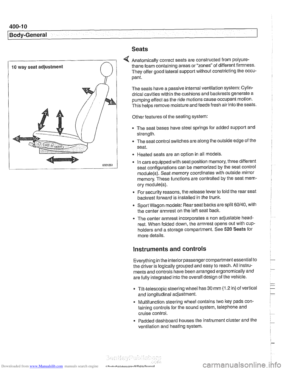
4 Anatomically correct seats are constructed from polyure-
10 way seat adjustment thane foam
containing areas or "zones" of different firmness.
They offer good lateral support without constricting the occu-
pant.
The seats have a passive internal ventilation system: Cylin-
drical cavities within the cushions and backrests generate a
pumping effect as the ride motions cause occupant motion.
This
helps remove moisture and feeds fresh air into the seats.
Other features of the seating system:
The seat bases have steel springs for added support and
strength.
The seat control switches are along the outside edge of
the
seat.
Heated seats are an option in all models
In cars equipped with seat position memory, three different
seat confiaurations can be memorized by the seat control
module(s): Seat memory coordinates with outside mirror
memory. These functions are controlled by the seat mem-
ory
module(s).
* For security reasons, the release lever to fold the rear seat
backrest forward is installed in the trunk.
Sport Wagon models: Rear seat
baclts are split 60140, with
the center armrest on the left seat back.
The center armrest incorporates a non adjustable head-
rest. When folded down, the armrest opens out with
cup-
holders and a storage compartment. See 520 Seats for
more details.
instruments and controls
Everything in the interior passengercompartment essential to
the driver is logically grouped and easy to reach. All instru-
ments and controls have been arranged ergonomically and
are fully integrated into the overall design of the vehicle.
Tilt-telescopic steering wheel has
30 mm (1.2 in) of vertical
and longitudinal adjustment.
Multifunction steering wheel contains two
ltey pads con-
taining controls for the sound system, telephone and
cruise control.
Padded dashboard houses the instrument cluster and the
ventilation and heating system.
Page 805 of 1002
Downloaded from www.Manualslib.com manuals search engine
Instrument cluster
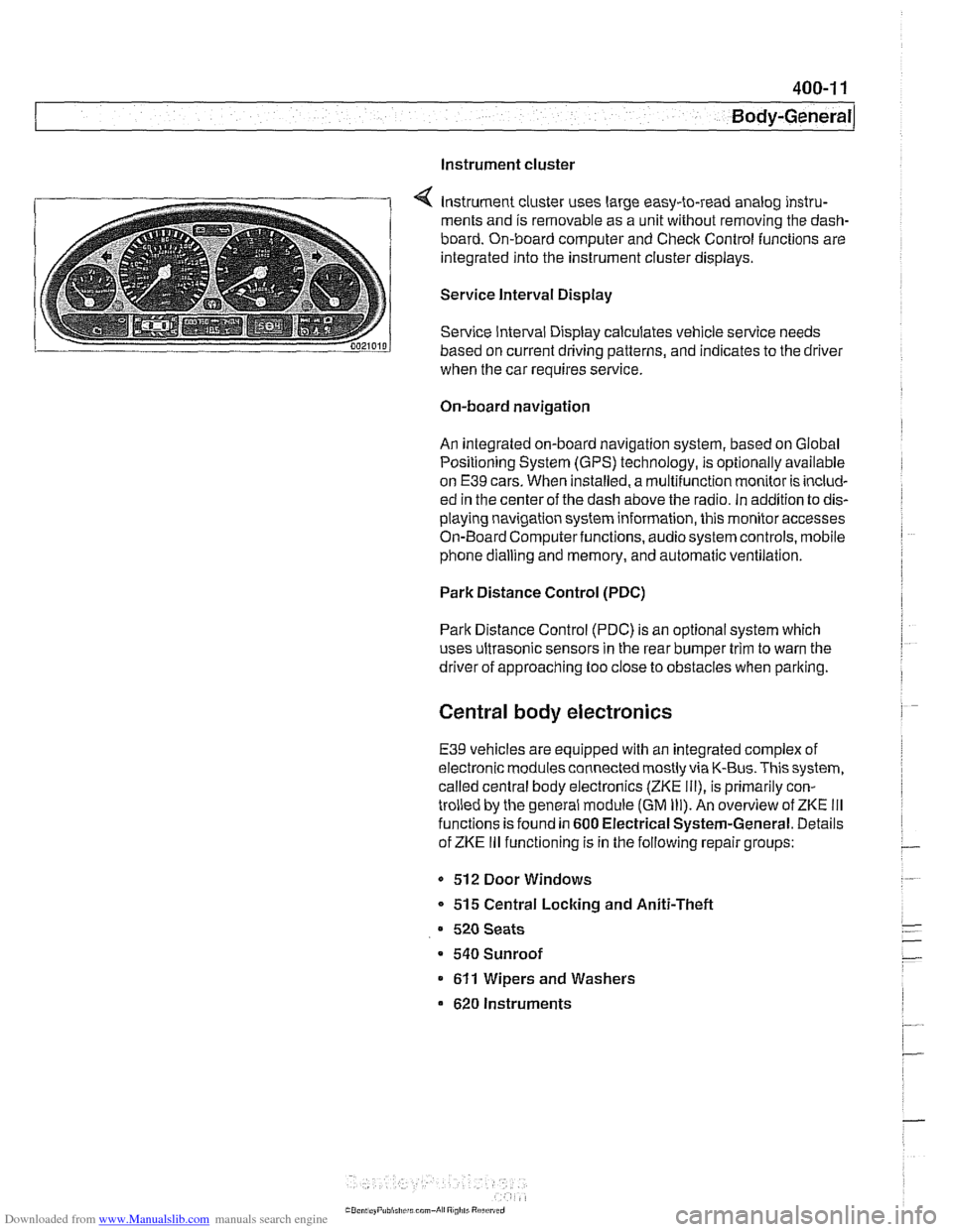
Instrument cluster uses large easy-to-read analog instru-
ments and is removable as a unit without removing the dash-
board. On-board computer and Check Control functions are
integrated into the instrument cluster displays.
Service Interval Display
Service Interval Display calculates vehicle service needs
based on current driving patterns, and indicates to the driver
when the car requires
service
On-board navigation
An integrated on-board navigation system, based on Global
Positioning System (GPS) technology, is optionally available
on
E39 cars. When installed, a multifunction monitor is includ-
ed in the center of the dash above the radio. in addition to dis-
playing navigation system information, this monitor accesses
On-Board Computerfunctions, audiosystem controls, mobile
phone dialling and memory, and automatic ventilation.
Park Distance Control (PDC)
Park Distance Control (PDC) is an optional system which
uses ultrasonic sensors in the rear bumper trim to warn the
driver of approaching too close to obstacles when parlting.
Central body electronics
E39 vehicles are equipped with an integrated complex of
electronic modules connected mostly via K-Bus. This system,
called central body electronics (ZKE
Ill), is primarily con-
trolled by the general module (GM
Ill). An overview of ZKE Ill
functions is found in 600 Electrical System-General. Details
of ZKE
Ill functioning is in the following repair groups:
- 512 Door Windows
* 515 Central Locking and Aniti-Theft
520 Seats
a 540 Sunroof
611 Wipers and Washers
620 Instruments
Page 893 of 1002
Downloaded from www.Manualslib.com manuals search engine
51 3-1 5
I Interior Trim
Dash panel support, removing and
installing
- Remove lower dash panel. See Lower dash panel assem-
bly, removing and installing.
- Remove upper dash panel. See Upper dash assembly, re-
moving and installing.
- Remove upper steering column fasteners. See 320 Steering
and Wheel Alignment.
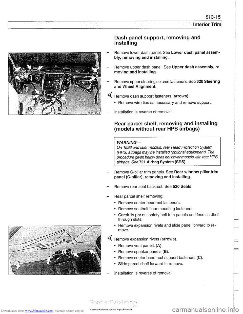
4 Remove dash support fasteners (arrows).
Remove wire ties as necessary and remove support.
- Installation is reverse of removal.
Rear parcel shelf, removing and installing
(models without rear
HPS airbags)
WARNING-
On 1998 and later models, rear Head Protection System
(HPS)
airbags may be installed (optional equipment). The
procedure given below does not covermodels with rear HPS
airbags. See721
Airbag System (SRS).
- Remove C-pillar trim panels. See Rear window pillar trim
panel (C-pillar), removing and installing.
- Remove rear seat backrest. See 520 Seats.
- Rear parcel shelf removing:
Remove center headrest fasteners.
Remove
seatbelt floor mounting fasteners.
Carefully pry out safety belt trim panels and feed
seatbelt
through slots.
. . . - -. . . . . . . . . Remove expansion rivets and slide pane fonvard to re-
move.
< Remove expanson r:vets (arrows).
Remove vent panels (A).
Remove speafter pane s (B).
Remove center head rest s-pporl fasteners (C).
Slioe parcel shelf forward lo remove.
- lnsta lation s reverse of removal.
Page 921 of 1002
Downloaded from www.Manualslib.com manuals search engine
........................ General ........................... .52 0.2 Rear Seats .52 0.7
SeatIMirrorlSteering Column Memory ..... .52 0.2 Rear seat cushion and backrest,
...... Seat memory position. setting ........... .52 0.2 removing and installing (sedan only) 520-7
......... Headrest. removing
and installing 520-8 Front Seats ........................ .52 0.4
Seat switch and memory module.
removing and installing
................ .52 0.3
Front seat. removing and installing
....... .52 0.5
Page 925 of 1002
Downloaded from www.Manualslib.com manuals search engine
520-5
Seats
1
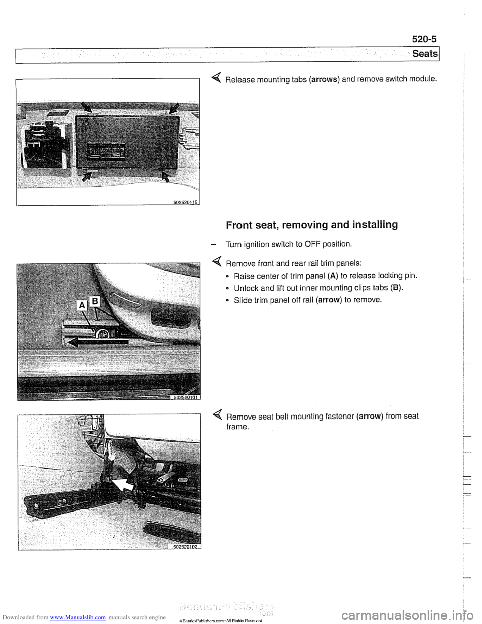
4 Release mounting tabs (arrows) and remove switch module.
Front seat, removing and installing
- Turn ignition switch to OFF position.
Remove front and rear rail trim panels:
Raise center of trim panel
(A) to release loclting pin.
Unlock and lift out inner mounting clips tabs
(6).
Slide trim panel off rail (arrow) to remove.
< Remove seat belt mounting fastener (arrow) from seat
frame.