M62 BMW 540i 2001 E39 Workshop Manual
[x] Cancel search | Manufacturer: BMW, Model Year: 2001, Model line: 540i, Model: BMW 540i 2001 E39Pages: 1002
Page 41 of 1002
Downloaded from www.Manualslib.com manuals search engine
--- -
Maintenance
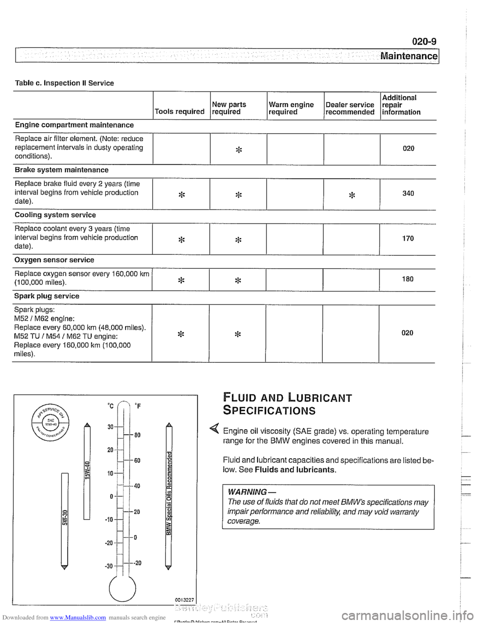
Table c. Inspection II Service
Additional
New parts Warm engine Dealer service repair
Tools required required required recommended information
Engine compartment maintenance
Replace air filter element. (Note: reduce
replacement intervals in dusty operating
conditions).
Replace brake
fluid every 2 years (time
interval begins from vehicle production
date).
Cooling system service
Spark plug service
Brake
system maintenance
:j:
*
Replace coolant every 3 years (time
interval begins from vehicle production
date).
Replace oxygen sensor every 160,000
itm
(1 00,000 miles).
020
FLUID AND LUBRICANT
SPECIFICATIONS
:I:
Oxygen sensor service
*
x:
Spark plugs:
M52
1 M62 engine:
Replace every 60,000 itm (48.000 miles).
M52
TU I M54 1 M62 TU engine:
Replace every 160,000
ltm (100.000
miles).
< Engine oil viscosity (SAE grade) vs. operating temperature
range for the BMW engines covered in this manual.
Fluid and lubricant capacities and specifications are listed be-
low. See
Fluids and lubricants.
:I:
*
*
*
WARNING -
The use of fluids that do not meet BMW" specifications may
impair performance and
reliabilitl: and may void warranty
coverage.
340
170
180
* 020
Page 52 of 1002
Downloaded from www.Manualslib.com manuals search engine
Maintenance
continue to operate as designed. Extending the replacement
interval may void the emission control warranty coverage.
See
180 Exhaust System for information on replacing the
oxygen sensors.
Tightening torque
Oxvoen sensor to exhaust
manifold 50 Nrn (37 ft-lb)
NOTE-
A special soclet for replacing the oxygen sensor is available
from most automotive parts stores. The soclet has
a groove
cut down one side to allow the sensor to be installed without
damaging the wire harness.
Power steering fluid, checking level
The power steering system is permanently filled and does not
have a drain. Routinely adding ATF is not required unless the
system is leaking.
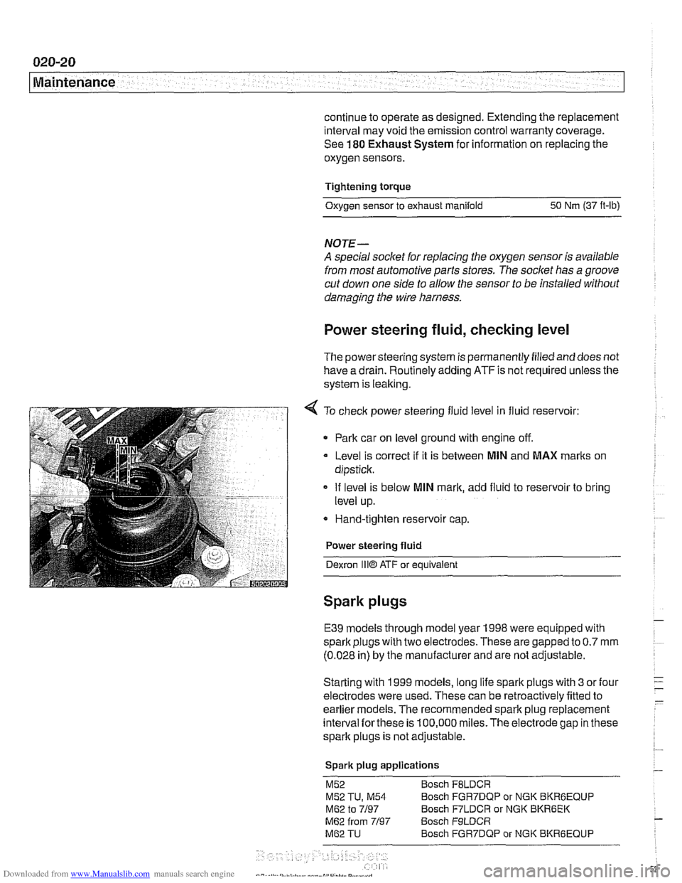
4 To check power steering fluid level in fluid reservoir:
Park car on level ground with engine off.
Level is correct
if it is between MlN and MAX marks on
dipstick.
If level is below
MlN mark, add fluid to reservoir to bring
level up.
* Hand-tighten reservoir cap.
Power steering fluid
Dexron
1iiO ATF or equivalent
Spark plugs
E39 models through model year 1998 were equipped with
spark plugs with two electrodes. These are gapped to
0.7 mm
(0.028 in) by the manufacturer and are not adjustable.
Starting with 1999 models, long life spark plugs with
3 or four
electrodes were used. These can be retroactively fitted to
earlier
models. The recommended spark plug replacement
interval
forthese is 100,000 miles.The electrode gap in these
spark plugs is not adjustable.
Spark plug applications
M52 Bosch FBLDCR
M52 TU, M54 Bosch FGR7DQP or NGK BKRBEQUP
M62 to 7/97 Bosch F7LDCR or NGK BKR6EK
M62 from 7/97 Bosch F9LDCR
M62 TU Bosch FGR7DQP or NGK BKRGEQUP
Page 59 of 1002
Downloaded from www.Manualslib.com manuals search engine
.-. -
Maintenance
Drive axle joint
(CV joint) boots, inspecting
CVjoint protective boots must be closely inspected forcracks
and any other damage that will allow contaminants to get into
the joint.
If the rubber boots fail, the water and dirt that enter
the joint will quickly damage it.
NOTE-
Replacement of the CVjoint boots and inspection of the
joints are described
in 331 Final Drive.
Exhaust system, inspecting
Exhaust system life varies widely according to driving habits
and environmental conditions. If short-distance driving pre-
dominates, the moisture and condensation in the system will
not fully dry out. This will lead to early corrosion damage and
more frequent replacement.
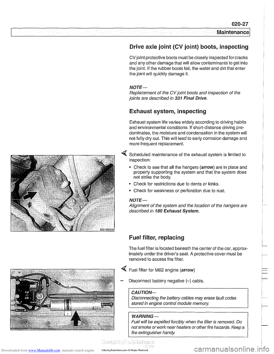
Scheduled maintenance of the exhaust system is limited to
inspection:
* Check to see that all the hangers (arrow) are in place and
properly supporting the system and that the system does
not strike the body.
Check for restrictions due to dents or
kinlts,
Check for weakness or perforation due to rust.
NOTE-
Alignment of the system and the location of the hangers are
described in
180 Exhaust System.
Fuel filter, replacing
The fuel filter is located beneath the center of the car, approx-
imately under the driver's seat.
A protective cover must be
removed to access the filter.
4 Fuel filter for M62 engine (arrow)
- Disconnect battery negative (-) cable
CAUTIOI\C
Disconnecting the battery cables may erase fault codes
stored
in engine control module memory.
WARNING -
Fuel will be expelled forcibly when the filter is removed. Do
notsmoke or work near heaters orother fire hazards. Keep a
fire extinguisher handy
Page 70 of 1002
Downloaded from www.Manualslib.com manuals search engine
100-4
I Engine-General
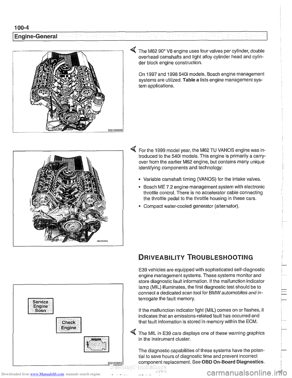
The M62 90" V8 engine uses four valves per cylinder, double
overhead camshafts and light alloy cylinder head and cylin-
der
bloclc engine construction.
On 1997 and 1998 540i models, Bosch engine management
systems are utilized. Table a lists engine management sys-
tem applications.
4 For the 1999 model year, the M62 TU VANOS engine was in-
troduced to the 540i models. This engine is primarily a carry-
over from the earlier M62 engine, but contains many unique
identifying components and technology:
Variable camshaft timing (VANOS) for the intake valves.
Bosch ME 7.2 engine management system with electronic
throttle control. There is no accelerator cable connecting
the throttle pedal to the throttle housing in these cars.
Compact water-cooled generator (alternator).
E39 vehicles are equipped with sophisticated self-diagnostic
engine management systems. These systems monitor and
store diagnostic fault information. If the malfunction indicator
lamp (MIL) illuminates, the first diagnostic test should be to
connect a dedicated scan tool for BMW automobiles and in-
terrogate the fault memory.
If the malfunction indicator light (MIL) comes on orflashes, it
indicates that an emissions-related fault has occurred and
that fault information is stored in memory within the ECM.
4 The MIL in E39 cars displays one of these warning graphics
in the instrument cluster.
The diagnostic capabilities of these systems have the poten-
tial to save hours of diagnostic time and prevent incorrect
5 placement. See OBD On-Board Diagnostics.
Page 90 of 1002
Downloaded from www.Manualslib.com manuals search engine
I Engine Removal and Installation
WARNING -
Use extreme caution when draining and disposing of engine
coolant. Coolant is poisonous andlethal to humans andpets.
Pets are attracted to coolant because of its sweet smell and
taste. Seek medical attention immediately if coolant is ingest-
---
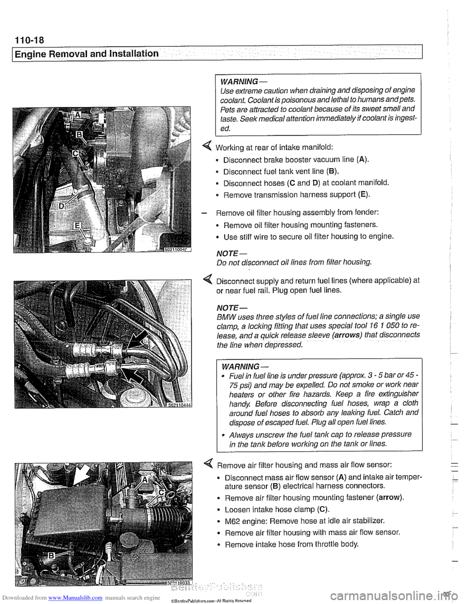
Working at rear of intake manifold:
Disconnect brake booster vacuum line (A).
Disconnect fuel tank vent line
(6).
Disconnect hoses (C and D) at coolant manifold
- Remove transmission harness support (E).
- Remove oil filter housing assembly from fender:
- Remove oil filter housing mounting fasteners.
Use stiff wire to secure oil filter housing to engine.
NOTE-
Do not disconnect oil lines from filter housing.
4 Disconnect supply and return fuel lines (where applicable) at
or near fuel rail. Plug open fuel lines.
NOTE-
BMW uses three styles of fuel line connections; a slngle use
clamp, a locking fitting that uses special tool
16 7 050 to re-
lease, and a
quiclc release sleeve (arrows) that disconnects
the line when depressed.
WARNING-
Fuel In fuel line is under pressure (approx. 3 - 5 bar or45 -
75 psi) and may be expelled. Do not smoke or worlc near
heaters or other fire hazards. Keep a fire extinguisher
handy. Before disconnecting fuel hoses, wrap a cloth
around fuel hoses to absorb any lealcing fuel. Catch and
dispose of escaped fuel. Plug all open fuel lines.
. Always unscrew the fuel tank cap to release pressure
in the tank before worlcing on the tank or lines.
< Remove air filter housing and mass air flow sensor:
Disconnect mass air flow sensor (A) and
intalte air temper-
ature sensor
(6) electrical harness connectors.
. Remove air filter housing mounting fastener (arrow).
Loosen intake hose clamp (C).
M62 engine: Remove hose at idle air stabilizer.
Remove air filter housing with mass air flow sensor.
Remove intalte hose from throttle body.
Page 91 of 1002
Downloaded from www.Manualslib.com manuals search engine
110-19
Engine Removal and Installation
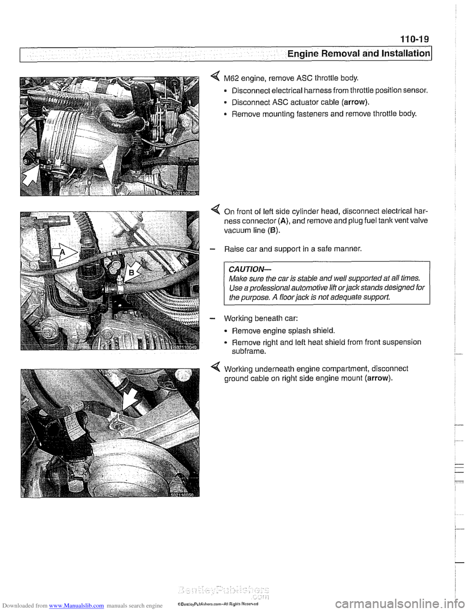
M62 engine, remove ASC throttle body.
Disconnect electrical harness from throttle position sensor.
- Disconnect ASC actuator cable (arrow).
. Remove mounting fasteners and remove throttle body.
On front of left side cylinder head, disconnect electrical har-
ness connector
(A), and remove and plug fuel tank vent valve
vacuum line
(0).
Raise car and support in a safe manner.
CAUTION-
Male sure the car is stable and well supported at aN times.
Use a professional automotive
lifi orjackstands designed for
I the ouroose. A floor jack is not adequate support.
Working beneath car:
- Remove engine splash shield.
Remove right and left heat shield from front suspension
subframe.
Working underneath engine compartment, disconnect
ground cable on right side engine mount
(arrow).
Page 92 of 1002
Downloaded from www.Manualslib.com manuals search engine
11 0-20
Engine Removal and Installation
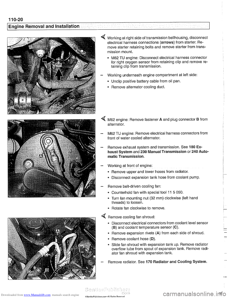
Working at right side of transmission bellhousing, disconnect
electrical harness connections (arrows) from starter. Re-
move starter retaining bolts and remove starter from trans-
mission mount.
M62 TU engine: Disconnect electrical harness connector
for right oxygen sensor from retaining clip and remove re-
taining clip from transmission.
- Working underneath engine compartment at left side:
Unclip positive battery cable from oil pan.
. Remove alternator cooling duct.
4 M62 engine: Remove fastener A and plug connector B from
alternator.
- M62 TU engine: Remove electrical harness connectors from
front of water cooled alternator.
- Remove exhaust system and transmission. See 180 Ex-
haust System and 230 Manual Transmission or 240 Auto-
matic Transmission.
- Working at front of engine:
Remove upper and lower hoses from radiator.
D~sconnect expansion tank hose from coolant pump.
- Remove belt-driven cooling fan:
Counterhold fan with special tool
11 5 050.
Turn fan mounting nut (32 mm) clockwise (left hand
threads) to loosen.
Rotate fan clockwise to remove.
Remove cooling fan shroud:
Disconnect electrical connectors from coolant level sensor
(B) and coolant temperature sensor (C).
. Remove expansion rivets (A) from each side of shroud
Remove coolant hose
(D).
Slide fan shroud with expansion tank up. Remove radiator
overflow tube from spout of expansion tank. Remove radi-
ator fan shroud with expansion tank.
Remove radiator. See
170 Radiator and Cooling System.
Page 95 of 1002
Downloaded from www.Manualslib.com manuals search engine
113-1
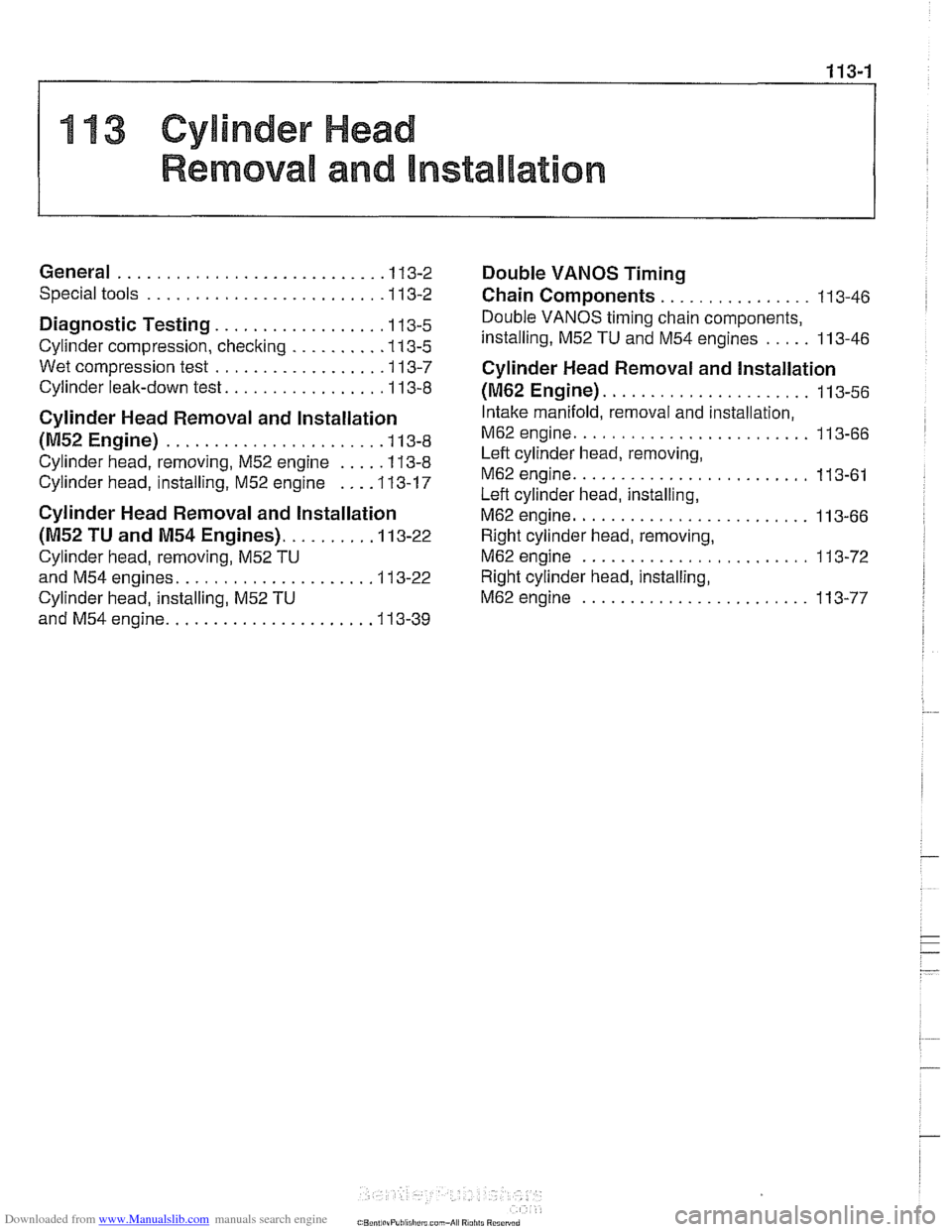
11 3 Cylinder Head
Removal and Installation
General ........................... .I 13-2
Special tools ........................ .I 13-2
Diagnostic Testing. ................ .I1 3-5
Cylinder compression, checking ......... ,113-5
Wet compression test ................. .I1 3-7
Cylinder leak-down test. ................ 11 3-8
Cylinder Head Removal and Installation
(M52 Engine) ...................... .I1 3-8
Cylinder head, removing, M52 engine .... ,113-8
Cylinder head, installing, M52 engine ... ,113-17
Cylinder Head Removal and Installation
(M52 TU and M54 Engines). ........ ,113-22
Cylinder head, removing, M52 TU
and
M54 engines. ................... .I1 3-22
Cylinder head, installing, M52 TU
and
M54 engine. .................... .I1 3-39
Double VANOS Timing
Chain Components
................ 11 3-46
Double VANOS timing chain components,
installing,
M52 TU and M54 engines ..... 113-46
Cylinder Head Removal and Installation
(M62 Engine). ..................... 11 3-56
Intake manifold, removal and installation,
M62 engine. ........................ 11 3-66
Left cylinder head, removing,
M62 engine. ........................ 11 3-61
Left cylinder head, installing,
M62 engine. ........................ 11 3-66
Right cylinder head, removing,
M62 engine ........................ 11 3-72
Right cylinder head, installing,
M62 engine ........................ 11 3-77
Page 96 of 1002
Downloaded from www.Manualslib.com manuals search engine
11 3-2
Cylinder Head Removal and Installation
This group covers cylinder head removal and installation as
well as cylinder
headlvalve diagnostic procedures.
In the procedures in this repair group, engines are referred to
by engine code. If necessary, see
100 Engine-General for
engine code and application information.
The information given in this repair group assumes that the
engine is installed in the engine bay. On the
6-cylinder en-
gines, the VANOS control unit must be removed in orderto re-
move the cylinder head from the engine block. On
M52TU
and M54 engines, camshafts must be removed from the cylin-
der head before the head is removed.
The cylinder head removal and installation procedures for the
M62 V-8 are also included, butthe proceduresforthe M62TU
V-8 with VANOS are not provided.
For cylinder head and valvetrain reconditioning information,
see
116 Cylinder Head and Valvetrain.
For specific repair procedures, refer to the appropriate repair
group:
020 Maintenance
116 Cylinder Head and Valvetrain
117 Camshaft Timing Chain
170 Radiator and Cooling System
610 Component locations
NOTE-
If a head gasket problem is suspected, a compression test or
leak-down test will usually detect the fault See Diagnostic
Testing later
in this group.
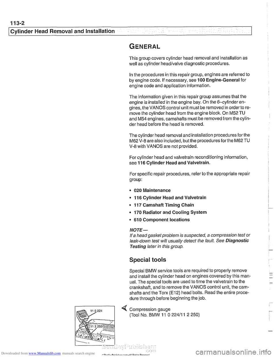
Special tools
Special BMW service tools are required to properly remove
and install the cylinder head on engines covered by this man-
ual. The special tools are used to time the valvetrain to the
crankshaft, and to remove the VANOS control unit, the cam-
shafts and the
Tom (El2) head bolts. Read the entire proce-
dure through before beginning the job.
Page 150 of 1002
Downloaded from www.Manualslib.com manuals search engine
11 3-56
I Cvlinder Head Removal and Installation
- Installation of the remaining parts is reverse or removal, not-
ing the following:
- Refill cooling system as described in 170 Radiator and
Cooling System.
Change engine oil and filter as described in
020 Mainte-
nance.
If necessary, adjust accelerator cable.
a Reconnect battery.
CAUTION- To prevent damaging the engine electronic systems, installall
ground wire previously removed, including the ground wires
for the
ionition coils.
Tightening torque Coolant drain
pluq to cylinder bloclc 25 Nm (1 8 ft-lb)
Radiator cooling fan to coolant pump 40 Nm (30 ft-lb) -
Radiator drain screw to radiator 2.5
Nm (22 in-lb)
spark plug to cylinder head 25
Nm (1 8 ft-lb)
CYLINDER MEAD REMOVAL AND
INSTALLATION (M62 ENGINE)
This procedure covers cylinder head removal and installation
for the
M62 V-8 engine. Procedures forthe M62 TU VANOS
engine are not covered in this manual.
Intake manifold, left cylinder head, and right cylinder head re-
moval and installation are written as separate procedures.
The intake manifold must be removed before the cylinder
heads can be removed.
WARNING
-
Due to risk of personal injuv be sure the engine is cold be-
fore beginning the removal procedure.
Cylinder head removal and installation requires multiple spe-
cial service tools. Read the entire procedure before beginning
the repair.
Intake manifold, removal and installation,
M62 engine
- Disconnect negative (-) battery cable.
CAUTION- Prior to disconnecting the
batterj read the baitery discon-
nection cautions
in 001 General Cautions and Warnings.