dashboard BMW 540i 2001 E39 Workshop Manual
[x] Cancel search | Manufacturer: BMW, Model Year: 2001, Model line: 540i, Model: BMW 540i 2001 E39Pages: 1002
Page 9 of 1002
Downloaded from www.Manualslib.com manuals search engine
002 Vehicie identification and
VlN Decoder
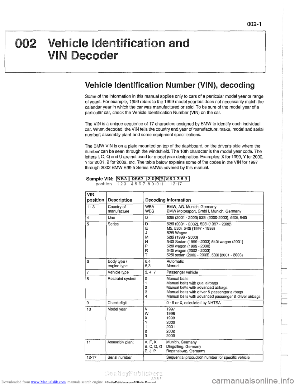
Vehicle identification Number (VIN), decoding
Some of the information in this manual applies only to cars of a parlicuiar model year or range
of vears. For
examole. 1999 refers to the 1999 model vear but does not necessarilv malch the
caiendsr year in which the car was manufactured or sold. To be sure of the model year of a
particular car,
checic the Vehicle ldentification Number (VIN) on the car.
The VIN is a unique sequence of 17 characters assigned by BMW lo identify each individual
car. When decoded, the VIN tells the country and year of manufacture; make, model and serial
number: assembly
plant and some equipment specifications.
The BMW VIN is on a plate mounted on top of the dashboard, on the driver's side where the
number can be seen through the windshield, The 10th character is the model year code. The
letters
I. 0, Q and U are not used for model year designation. Examples: X for 1999, Y for 2000,
1 for 2001,2 for 2002, etc. The table below explains some of the codes in the VIN for 1997
through 2002 BMW
E39 5 Series BMWs covered by this manual.
Sample
VIN: ~~Iz~o~w~B~w~ 13 8 9 1 lposition 1 2 3 zi 5 6 7 8 9 10 11 12-17
VIN
position Description Decoding information
1-3 Countrv of WBA B
I J 1 znan~+q ;BT BMW Molorsporl. Gmon, ~;nch Gerrn;!n,
Linc 525 (2UU1 - 2003) 528 (2000-2003. 530; 540 i
5
1
Manual belts with dual airbags Manual belts with advanced airbaos
Series
Body
type
i engine lype . ..
D 5251 (2001 - 2002), 528i (1997 - 2000) E MS. 530i, 540i (1997 - 1998) J 5251 Wagon
M 528i (1999 - 2000) N 5401 Sedan (1999 - 2003) 540i wagon (2001)
P 528i wagon (1999 - 2000) R 540i waaon 12002 - 20031
6,4 Aulomatic 5,3 Manual
Vehicle type 3.4.7 Passenger vehicle
Checlr digit
Model year Restraint
system
1 0 Manual belts
3 Manual belts wilh driver
& passenger airbags 4
Manual belts with advanced passenger B driver airbags
0 - 9 or X, calculated by NHTSA
V 1997 W 1RRR
Assembly plant A, F, K Munich, Germany
B, C, D, G Dingolfing. Germany E, J. P Reqensburq. Germany .
Serial number
Sequential produclion number lor specific vehicle
Page 630 of 1002
Downloaded from www.Manualslib.com manuals search engine
300-1 0
/Suspension, Steering and Brakes - General
The steering system features variable power assist provided
by an engine-driven hydraulic pump.
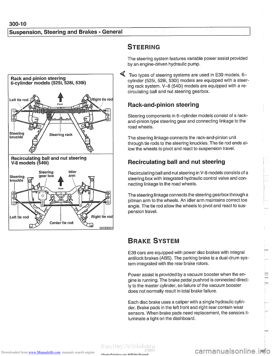
Rack and pinion steering
6-cylinder models
(525i, 5281, 5300
Two types of steering systems are used in E39 models. 6-
cylinder (525i, 5281, 530i) models are equipped with a steer-
ing rack system. V-8
(540i) models are equipped with a re-
circulating ball and nut steering gearbox.
Rack-and-pinion steering
Steering components in 6-cylinder models consist of a rack-
and-pinion type steering gear and connecting linltage to the
road wheels.
The steering linkage connects the rack-and-pinion unit
through tie rods to the steering knucltles. The tie rod ends al-
low the wheels to pivot and react to suspension travel.
Recirculating ball and nut steering
V-8 models
(540i)
I
Recirculating ball and nut steering
Recirculating ball and nut steering in V-8 models consists of a
steering box with integrated hydraulic control valve and con-
necting linkage to the road wheels.
Thesteering linkageconnects the steering gearbox through a
pitman arm to the wheels. An idler arm maintains correct toe
angle. The tie rod allow the wheels to pivot and react to sus-
pension travel.
E39 cars are equipped with power disc brakes with integral
antilock brakes (ABS). The parking bralte is a dual-drum sys-
tem integrated with the rear brake rotors.
Power assist is provided by a vacuum booster when the en-
gine is running. The brake pedal
pushrod is connected direct-
ly to the master cylinder, so failure of the vacuum booster
does not normally result in total
bralte failure.
Each disc bralte uses a caliper with a single hydraulic cylin-
der. Brake pads in the left front and right rear contain wear
sensors. When brake pads need replacement, the sensors il-
luminate a light on the dashboard.
Page 804 of 1002
Downloaded from www.Manualslib.com manuals search engine
400-1 0
Body-General
Seats
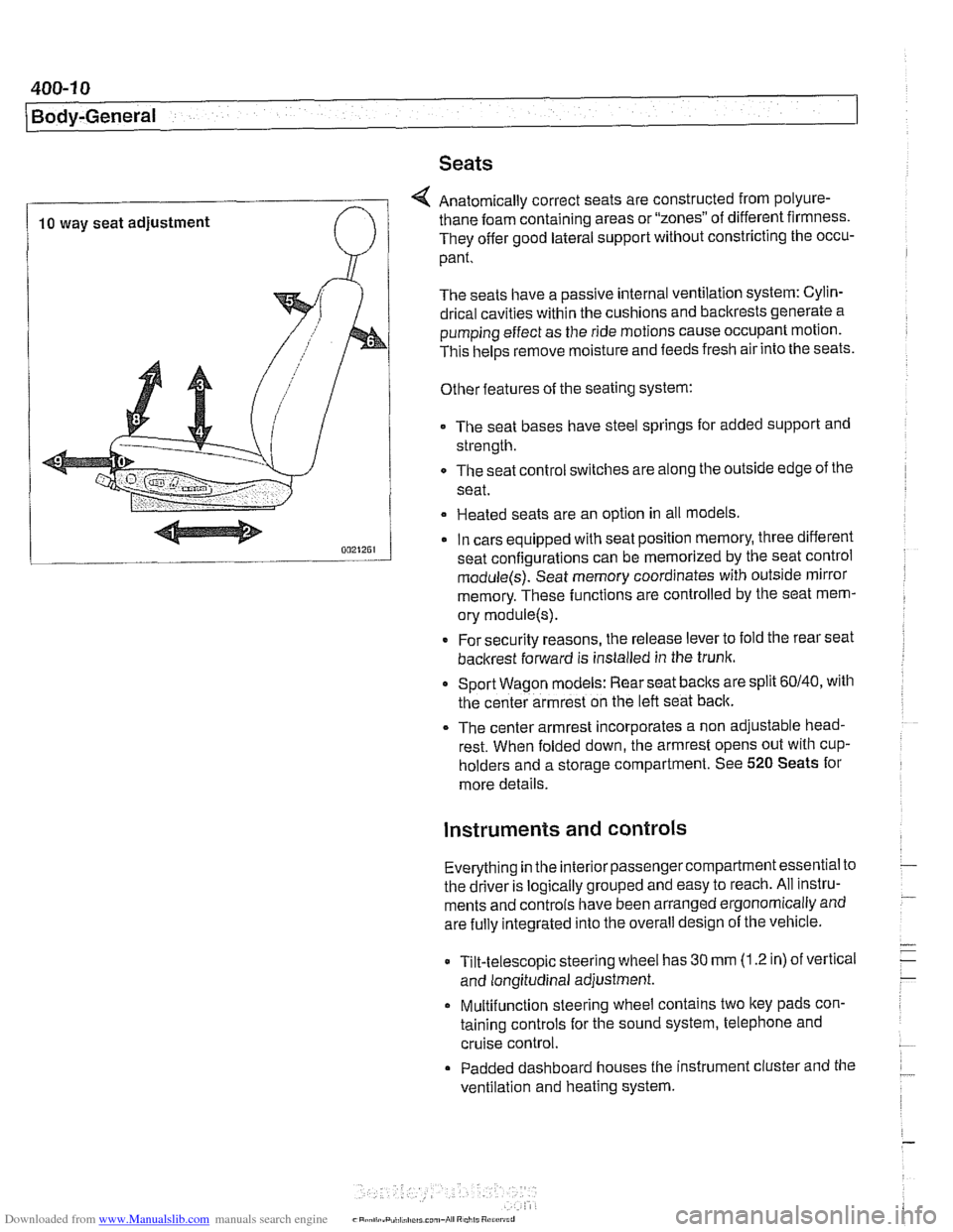
4 Anatomically correct seats are constructed from polyure-
10 way seat adjustment thane foam
containing areas or "zones" of different firmness.
They offer good lateral support without constricting the occu-
pant.
The seats have a passive internal ventilation system: Cylin-
drical cavities within the cushions and backrests generate a
pumping effect as the ride motions cause occupant motion.
This
helps remove moisture and feeds fresh air into the seats.
Other features of the seating system:
The seat bases have steel springs for added support and
strength.
The seat control switches are along the outside edge of
the
seat.
Heated seats are an option in all models
In cars equipped with seat position memory, three different
seat confiaurations can be memorized by the seat control
module(s): Seat memory coordinates with outside mirror
memory. These functions are controlled by the seat mem-
ory
module(s).
* For security reasons, the release lever to fold the rear seat
backrest forward is installed in the trunk.
Sport Wagon models: Rear seat
baclts are split 60140, with
the center armrest on the left seat back.
The center armrest incorporates a non adjustable head-
rest. When folded down, the armrest opens out with
cup-
holders and a storage compartment. See 520 Seats for
more details.
instruments and controls
Everything in the interior passengercompartment essential to
the driver is logically grouped and easy to reach. All instru-
ments and controls have been arranged ergonomically and
are fully integrated into the overall design of the vehicle.
Tilt-telescopic steering wheel has
30 mm (1.2 in) of vertical
and longitudinal adjustment.
Multifunction steering wheel contains two
ltey pads con-
taining controls for the sound system, telephone and
cruise control.
Padded dashboard houses the instrument cluster and the
ventilation and heating system.
Page 806 of 1002
Downloaded from www.Manualslib.com manuals search engine
400-12
I Body-General
HEATING AND AIR ~ONDITIONING
(I H KA)
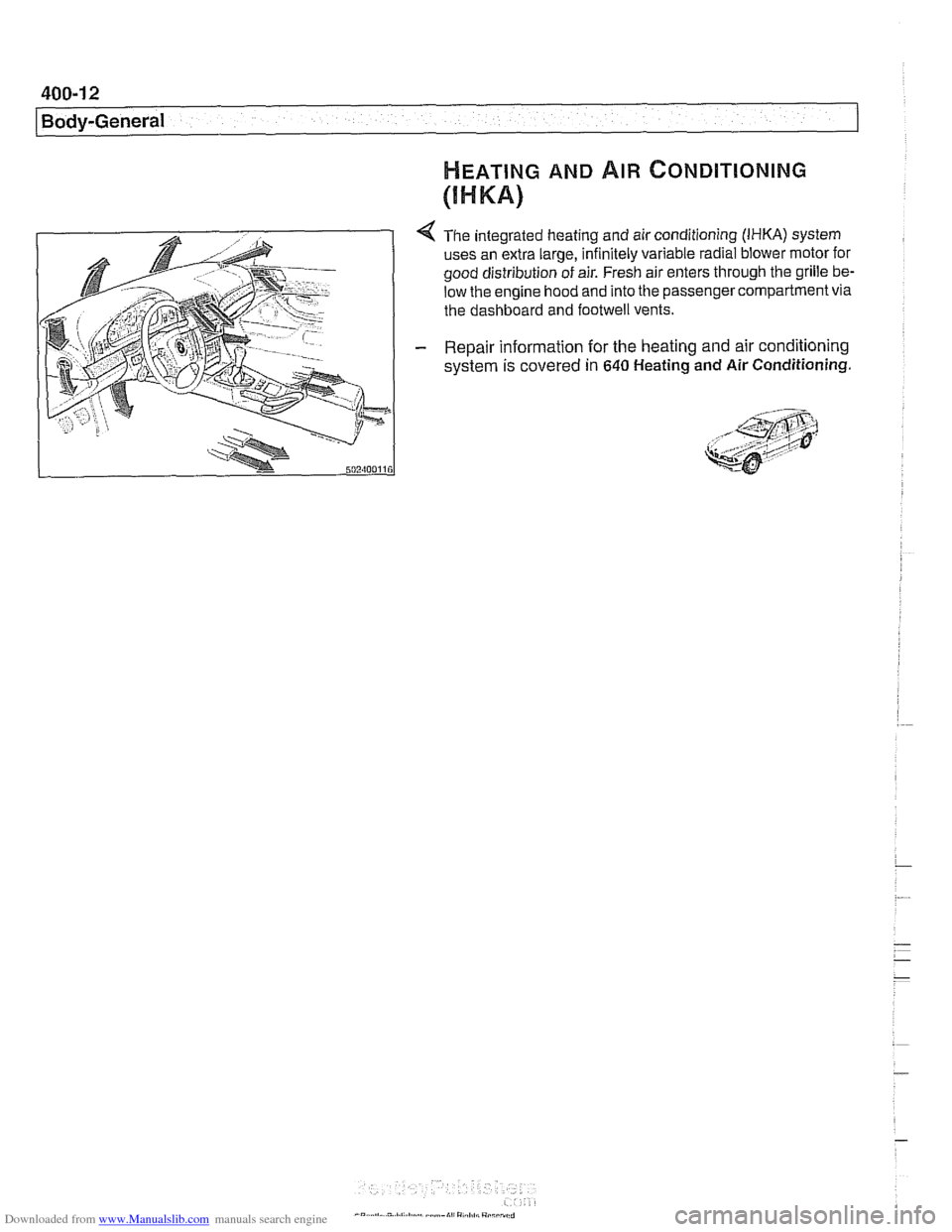
4 The integrated heating and air conditioning (IHKA) system
uses an extra large, infinitely variable radial blower motor for
good distribution of air. Fresh air enters through the grille
be.
low the engine hood and into the passenger compartment via
the dashboard and
footwell vents.
- Repair information for the heating and air conditioning
system is covered
in 640 Heating and Air Conditioning.
Page 885 of 1002
Downloaded from www.Manualslib.com manuals search engine
Interior Trim
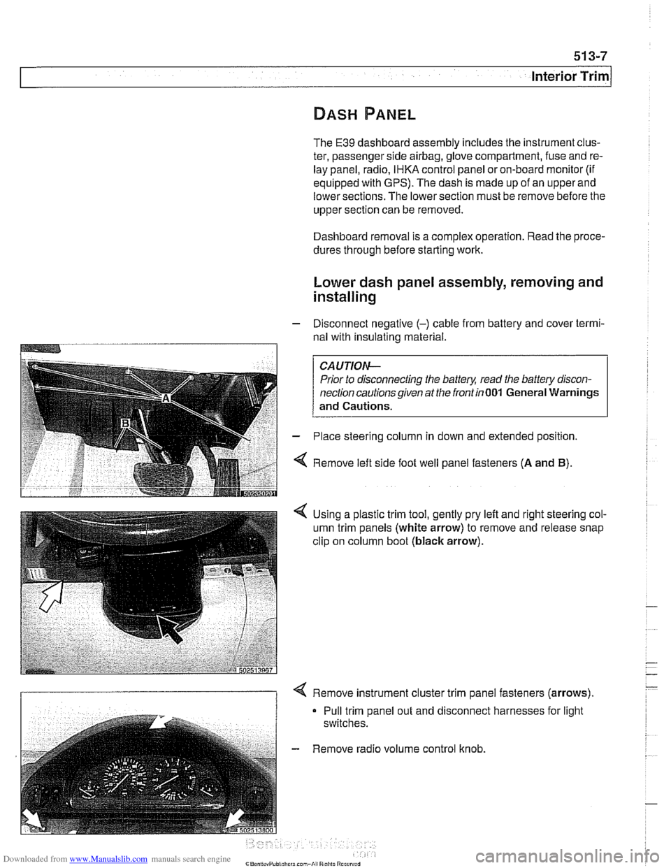
The E39 dashboard assembly includes the instrument clus-
ter, passenger side
airbag, glove compartment, fuse and re-
lay panel, radio. IHKA control panel oron-board monitor (if
equipped with GPS). The dash is made up of an upper and
lower sections. The lower section must be remove before the
upper section can be removed.
Dashboard removal is a complex operation. Read the proce-
dures through before starting work.
Lower dash panel assembly, removing and
installing
- Disconnect negative (-) cable from battery and cover termi-
nal with
insulating material.
--7
CAUTION-
Prior to disconnecting the battery, read the battery discon-
nectioncautionsgiven atthe irontin001 General Warnings
and Cautions.
- Place steering column in down and extended position.
4 Remove left side foot well panel fasteners (A and B).
< Using a plastic trim tool, gently pry left and right steering col-
umn trim panels (white arrow) to remove and release snap
clip on column boot
(black arrow).
I 1 < Remove instrument cluster trim panel fasteners (arrows).
Pull trim panel out and disconnect harnesses for light
switches.
- Remove radio volume control knob.
Page 886 of 1002
Downloaded from www.Manualslib.com manuals search engine
I Interior Trim
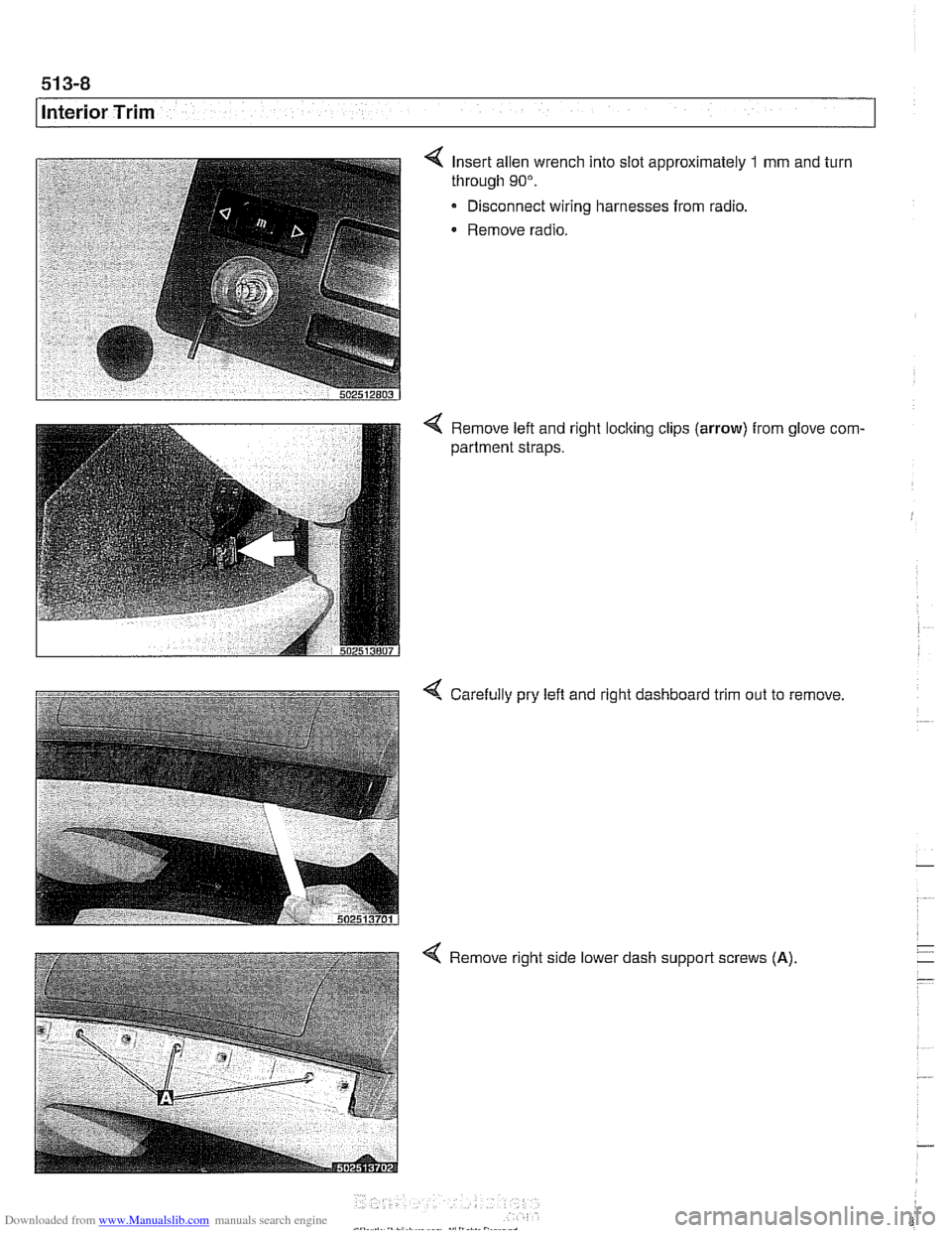
Insert allen wrench into slot approximately 1 mm and turn
through
90".
Disconnect wiring harnesses from radio.
Remove radio.
4 Remove left and right locking clips (arrow) from glove com-
partment straps.
4 Carefully pry left and right dashboard trim out to remove
4 Remove right side lower dash support screws (A)
Page 916 of 1002
Downloaded from www.Manualslib.com manuals search engine
Central Locking and Anii-Theft
- If the starter engages, the following EWS inputs are function-
ing normally:
Ignition key
Code function
Transmission range switch or clutch position switch
Engine speed sensor
NO JE -
If a vehicle key is lost or stolen, the electronic authorization
for that key
can be cancelled using the BMW scan and di-
agnostic tools
DISplus, GTl or MoDiC.
Force applied to a ley can damage the electronic circuitry
in the key A damaged ley will not start the engine. In that
case, a new key should be purchased and initialized
by an
authorized BMW dealer.
EWS variations
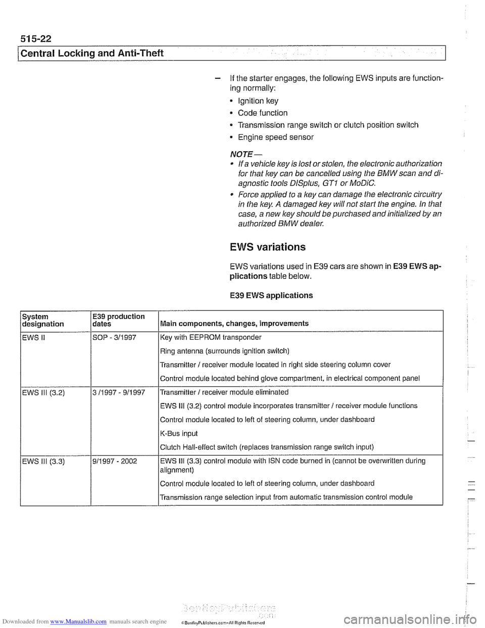
EWS variations used in E39 cars are shown in E39 EWS ap-
plications
table below.
E39
EWS applications
I I Ifling antenna (surrounds ignition switch) I
System
designation
EWS
II
I I l~ransmitter I receiver module located in right side steering column cover I
E39 production
dates
SOP
- 311 997
I I IEWS 111 (3.2) control module incorporates transmitter1 receiver moduie functions /
Main components, changes, improvements
Key with EEPROM transponder
Control moduie located behind glove compartment, in electrical component panel
Control module located to left of steering column, under dashboard
K-Bus input
Transmitter
I receiver module eliminated
EWS 111 (3.2)
Transmission range selection input from automatic transmission control module
3
11997 - 911997
- EWS ill (3.3) Clutch
Hall-effect switch (replaces transmission range switch input)
911997 - 2002 EWS 111 (3.3) control
module with iSN code burned in (cannot be overwritten during
alignment)
Control module located to left of steering column, under dashboard
Page 958 of 1002
Downloaded from www.Manualslib.com manuals search engine
721 -1 0
/Airbag System (SRS)
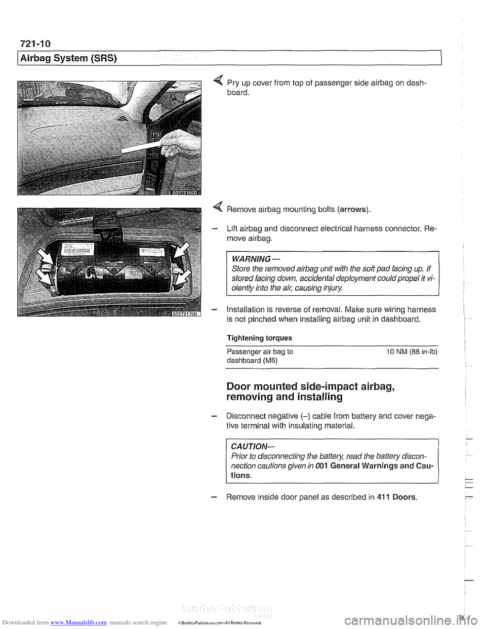
4 Pry up cover from top of passenger side airbag on dash-
board.
4 Remove airbag mounting bolts (arrows)
- Lift airbag and disconnect electrical harness connector. Re-
move
airbag.
WARNING-
Store the removed airbag unit with the soft pad facing up. If
stored facing down, accidental deployment could propel it vi-
olentlv into the
ail: causino inium
- Installation is reverse of removal. Make sure wiring harness
is not pinched when installing
airbag unit in dashboard.
Tightening torques
-
Passenger alr bag to 10 NM (88 in-lb)
dashboard (Me)
Door mounted side-impact airbag,
removing and installing
- Disconnect negatlve (-) cable from battery and cover nega-
tive terminal with insulating material.
CAUTION-
Prior to disconnecting the battea read the battery discon-
nection cautions given
in 001 General Warnings and Cau-
tions.
- Remove inside door panel as described in 41 1 Doors
Page 960 of 1002
Downloaded from www.Manualslib.com manuals search engine
721-12
Airbag System (SRS)
Head protection airbag (HPS)
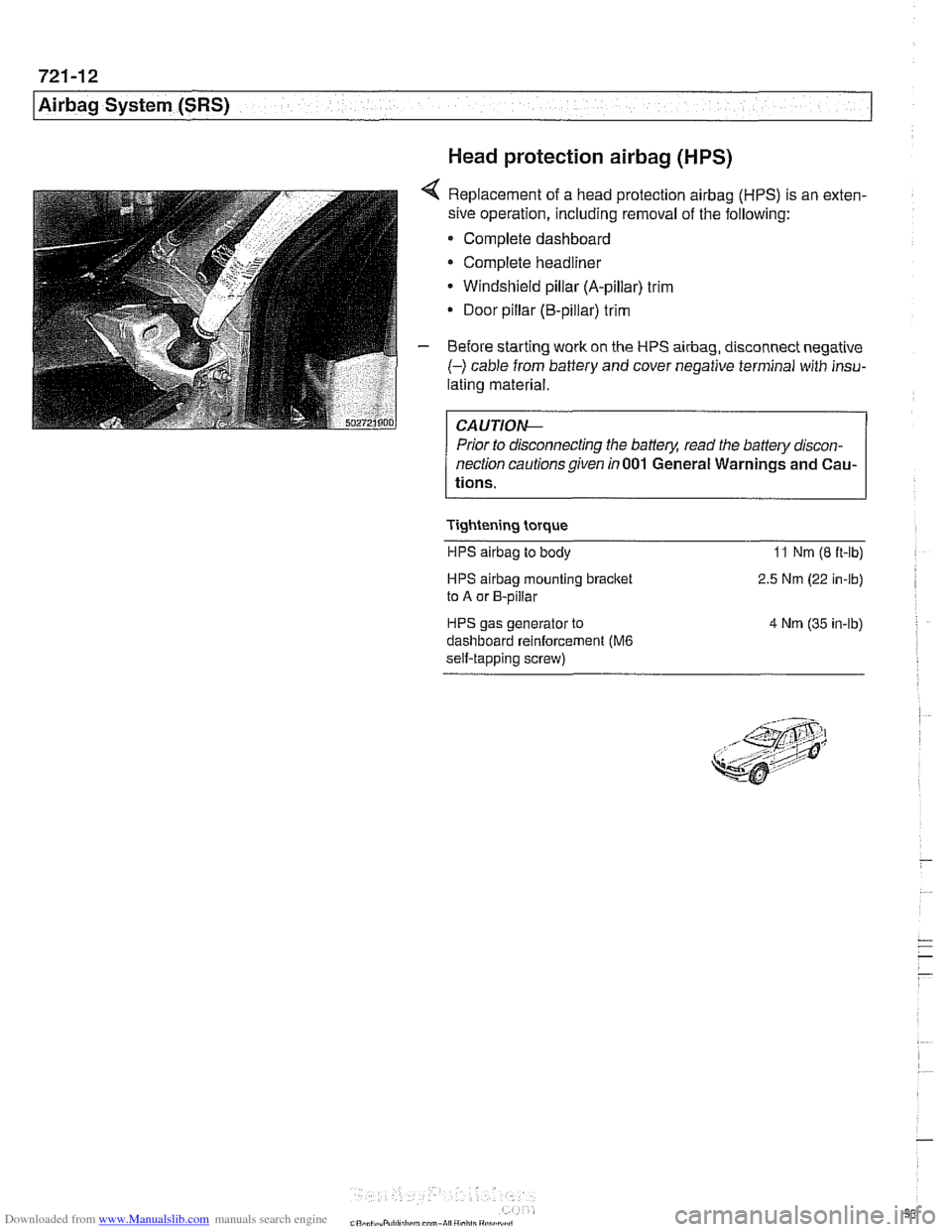
4 Replacement of a head protection airbag (HPS) is an exten-
sive operation, including removal of the following:
Complete dashboard
Complete headliner
Windshield pillar (A-pillar) trim
Door pillar (B-pillar) trim
- Before starting work on the HPS airbag, disconnect negative
(-) cable from battery and cover negative terminal with insu-
lating material.
Prior to disconnecting the battery, read the battery discon-
nection cautionsgiven in001 General Warnings and Cau-
tions.
Tightening torque HPS
airbag to body 11 Nm (8 ft-lb)
HPS airbag mounting bracket
to A or B-pillar
HPS gas generator to
dashboard reinforcement
(M6
self-tapping screw) 2.5
Nm (22 in-lb)
4 Nm (35 in-lb)
Page 962 of 1002
Downloaded from www.Manualslib.com manuals search engine
OED-2
On-Board Diagnostics
Specialized OED II scan tool equipment is needed to access
the fault memory and
OED I1 data.
The extra hardware needed to operate the OED
I1 system
consists mainly of the following:
* Additional oxygen sensors downstream of the catalytic
converters.
Fuel tank pressure sensor and device to pressurize
fuel
storage system.
Several engine and performance monitoring devices
Standardized 16-pin
OED II connector under the
dashboard.
Upgraded components for the federally required reliability
mandate.
Malfunction indicator light (MIL)
OED II software illuminates the malfunction indicator light
(MIL) when emission levels exceed 1.5 times Federal
standards.
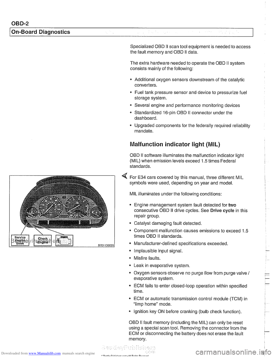
4 For E34 cars covered by this manual, three different MIL
symbols were used, depending on year and model.
MIL illuminates under the following conditions:
Engine management system fault detected for
two
consecutive OED iI drive cycles. See Drive cycle in this
repair group.
- Catalyst damaging fault detected.
Component malfunction causes emissions to exceed 1.5
times OED
II standards.
Manufacturer-defined specifications exceeded. Implausible input signal.
Misfire
faults.
Leak in evaporative system,
Oxygen sensors observe no purge
flow from purge valve 1
evaporative system.
ECM fails to enter closed-loop operation within specified
time.
ECM or automatic transmission control
module (TCM) in
"limp home" mode.
ignition key ON before cranking (bulb
check function).
OED
II fault memory (including the MIL) can only be reset
using a special scan tool. Removing the connector from the
ECM or disconnecting the battery does not erase the fault
memory.