key BMW 540I 2002 E39 Central Body Electronics ZKE Manual
[x] Cancel search | Manufacturer: BMW, Model Year: 2002, Model line: 540I, Model: BMW 540I 2002 E39Pages: 80, PDF Size: 4.14 MB
Page 33 of 80
Anti-Theft (DWA) System
Purpose of the System
The DWA alarm system offers vehicle protection by monitoring the doors, hood, interior,
luggage compartment and vehicle tilting. When activated, DWA deters theft by sounding
an alarm siren for 30 seconds, flashing the low beam headlights (high beam on Xenon
equipped models) and four way flashers for 5 minutes.
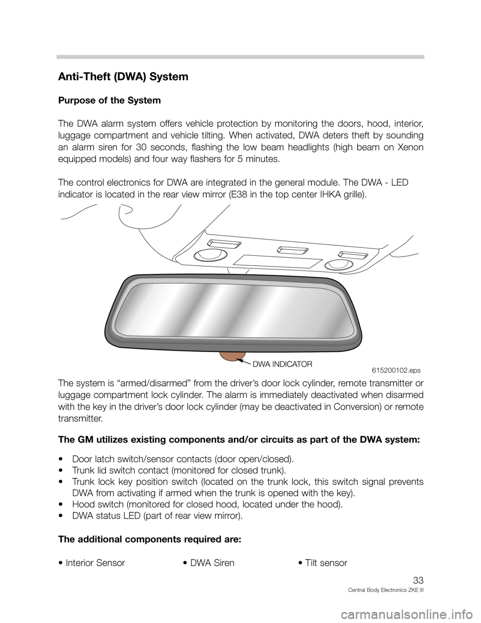
The control electronics for DWA are integrated in the general module. The DWA - LED
indicator is located in the rear view mirror (E38 in the top center IHKA grille).
The system is “armed/disarmed” from the driver’s door lock cylinder, remote transmitter or
luggage compartment lock cylinder. The alarm is immediately deactivated when disarmed
with the key in the driver’s door lock cylinder (may be deactivated in Conversion) or remote
transmitter.
The GM utilizes existing components and/or circuits as part of the DWA system:
• Door latch switch/sensor contacts (door open/closed).
• Trunk lid switch contact (monitored for closed trunk).
• Trunk lock key position switch (located on the trunk lock, this switch signal prevents
DWA from activating if armed when the trunk is opened with the key).
• Hood switch (monitored for closed hood, located under the hood).
• DWA status LED (part of rear view mirror).
The additional components required are:
• Interior Sensor • DWA Siren • Tilt sensor
33
Central Body Electronics ZKE III
615200102.eps
Page 40 of 80

Principle of Operation
DWA Arming/Disarming
• The DWA is armed every time the vehicle is locked from the outside with the door lock
cylinder or FZV key.
• The DWA LED flashes as an acknowledgment along with the exterior lights and a
momentary chirp from the siren.
• The GM monitors all required input signals for closed status (door closed, luggage com-
partment closed, etc.) The inputs must be in a closed status for a minimum of 3 sec-
onds for the GM to include them as an activation component. If after 3 seconds any
input signal not in the closed status is excluded (this is acknowledged by the DWA LED)
preventing false alarm activations. The hood switch can be “lifted” to the service posi-
tion to test the alarm with the hood open.
• If the DWA is armed a second time within 10 seconds, the tilt sensor and interior pro-
tection sensor are excluded as alarm activation components. This function is useful if
the vehicle is transported on a train or flat bed truck to prevent false alarm activations.
• While armed, the trunk can be opened with out the alarm being triggered as follows:
- If opened with the trunk remote button via the FZV, the GM prevents the alarm from
activating. (This feature is customizable under the Car Memory function).
- If opened with the key at the trunk lock cylinder the trunk key position switch sig-
nals the GM and in the same manner prevents the alarm from activating.
In either case, when the trunk is returned to the closed position, it is no longer con-
sidered as an activation signal.
Panic Mode Operation: When the trunk button is pressed and held, the GM is signaled
to activate the siren for the Panic Mode. The panic mode is function with either an armed
or disarmed DWA system.
Emergency Disarming: Emergency disarming occurs automatically if a key is used to turn
the ignition switch on and the EWS accepts it. The EWS signals the GM to unlock the doors
and deactivate the DWA.
40
Central Body Electronics ZKE III
Page 43 of 80
All window operations signals are digital inputs to the door module and GM III.
• Comfort closing/opening of the windows from the driver’s lock cylinder. The remote key
provides opening only.
• When the ignition key is in accessory or “on” position press the switch to open or close
the windows. Window operation is possible with the ignition switched off until a front
door is opened or 16 minutes (maximum) has elapsed.
• Window load switching is through relays. The front window control relays are located in
the door modules, the rear window relays are in the GM III. The GM III monitors the cur-
rent draw for end limit position. The maximum run time for the window motors is limit-
ed to 6 seconds in the one-touch mode. This allows the motors to be switched off if the
end limit load sensing fails.
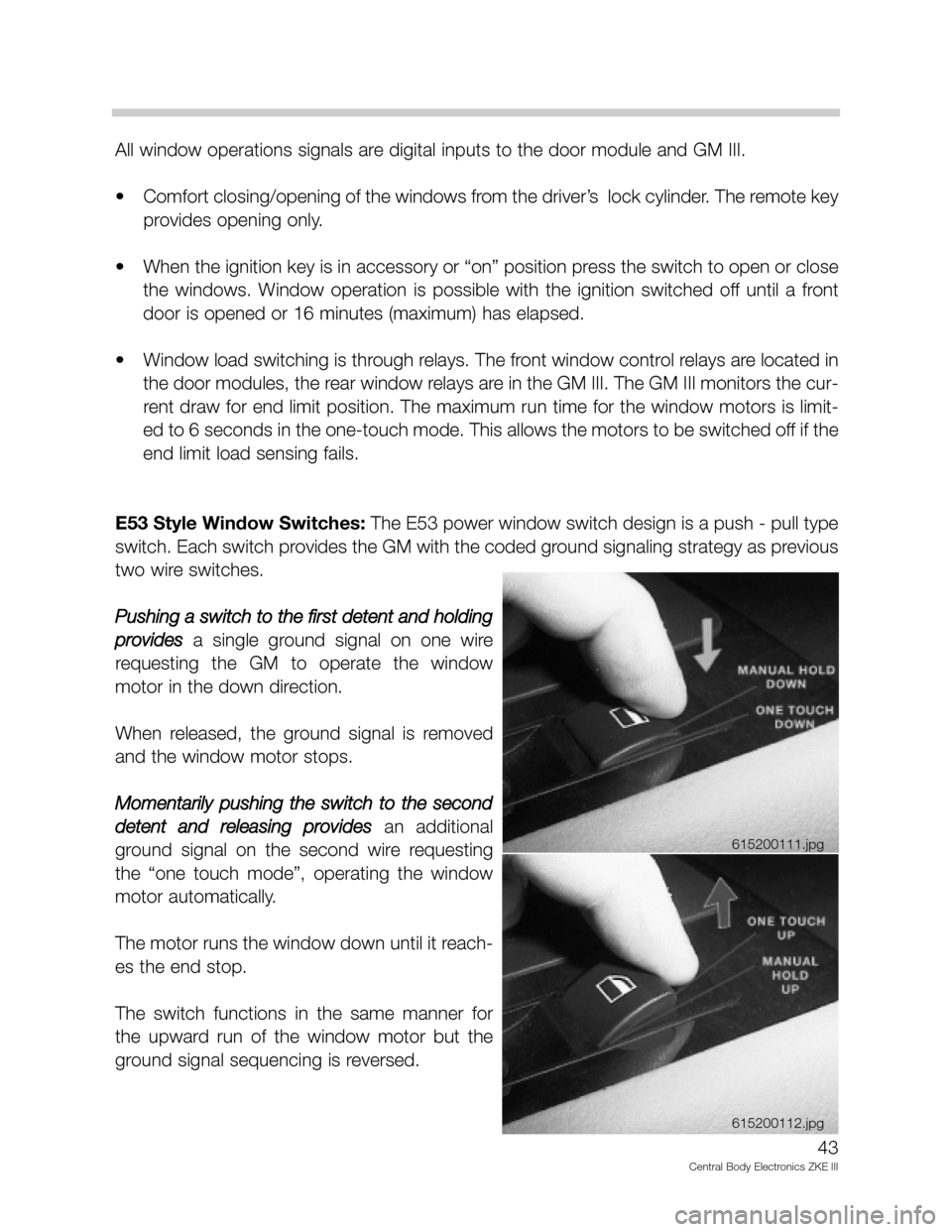
E53 Style Window Switches:The E53 power window switch design is a push - pull type
switch. Each switch provides the GM with the coded ground signaling strategy as previous
two wire switches.
Pushing a switch to the first detent and holding
provides
a single ground signal on one wire
requesting the GM to operate the window
motor in the down direction.
When released, the ground signal is removed
and the window motor stops.
Momentarily pushing the switch to the second
detent and releasing provides
an additional
ground signal on the second wire requesting
the “one touch mode”, operating the window
motor automatically.
The motor runs the window down until it reach-
es the end stop.
The switch functions in the same manner for
the upward run of the window motor but the
ground signal sequencing is reversed.
43
Central Body Electronics ZKE III
615200111.jpg
615200112.jpg
Page 46 of 80
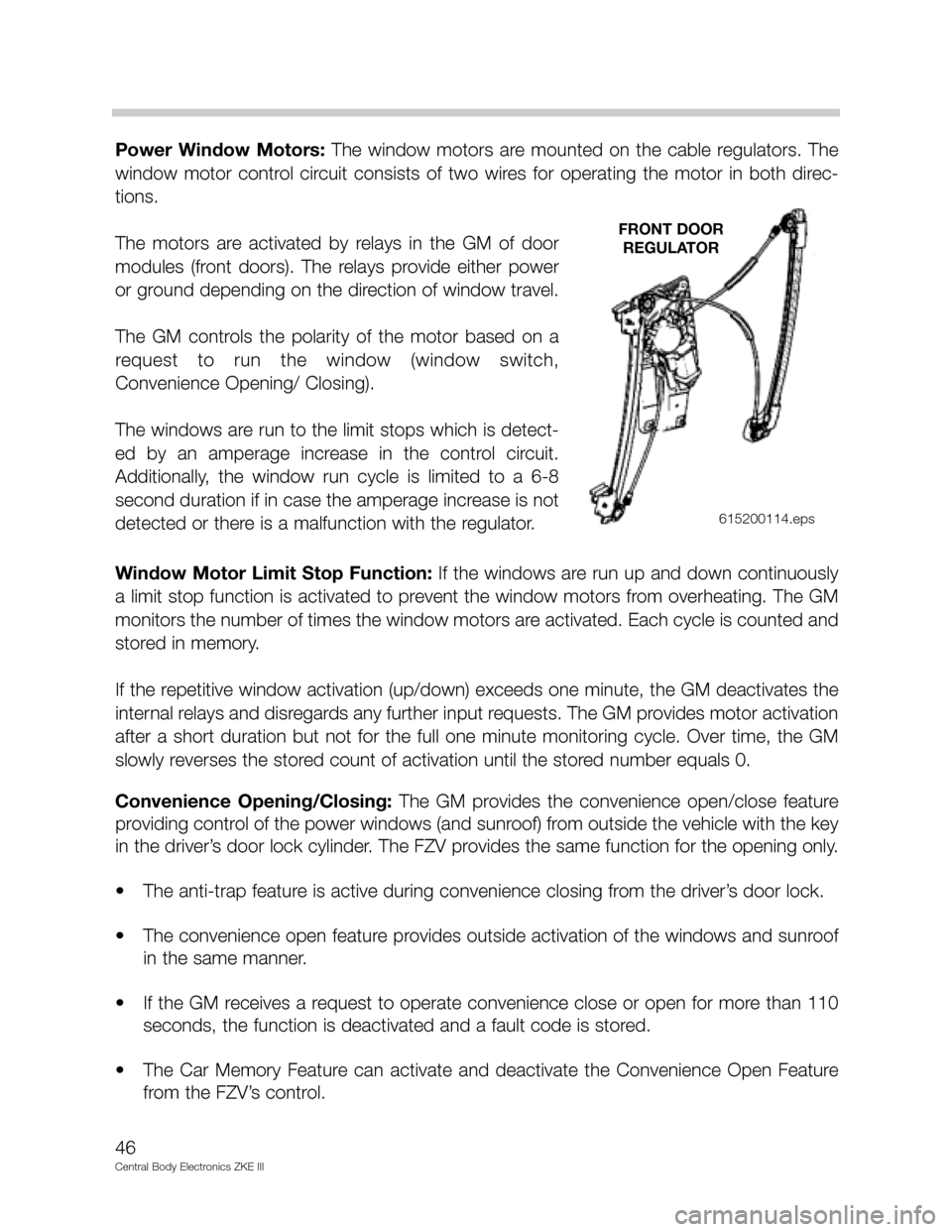
Power Window Motors: The window motors are mounted on the cable regulators. The
window motor control circuit consists of two wires for operating the motor in both direc-
tions.
The motors are activated by relays in the GM of door
modules (front doors). The relays provide either power
or ground depending on the direction of window travel.
The GM controls the polarity of the motor based on a
request to run the window (window switch,
Convenience Opening/ Closing).
The windows are run to the limit stops which is detect-
ed by an amperage increase in the control circuit.
Additionally, the window run cycle is limited to a 6-8
second duration if in case the amperage increase is not
detected or there is a malfunction with the regulator.
Window Motor Limit Stop Function: If the windows are run up and down continuously
a limit stop function is activated to prevent the window motors from overheating. The GM
monitors the number of times the window motors are activated. Each cycle is counted and
stored in memory.
If the repetitive window activation (up/down) exceeds one minute, the GM deactivates the
internal relays and disregards any further input requests. The GM provides motor activation
after a short duration but not for the full one minute monitoring cycle. Over time, the GM
slowly reverses the stored count of activation until the stored number equals 0.
Convenience Opening/Closing: The GM provides the convenience open/close feature
providing control of the power windows (and sunroof) from outside the vehicle with the key
in the driver’s door lock cylinder. The FZV provides the same function for the opening only.
• The anti-trap feature is active during convenience closing from the driver’s door lock.
• The convenience open feature provides outside activation of the windows and sunroof
in the same manner.
• If the GM receives a request to operate convenience close or open for more than 110
seconds, the function is deactivated and a fault code is stored.
• The Car Memory Feature can activate and deactivate the Convenience Open Feature
from the FZV’s control.
46
Central Body Electronics ZKE III
FRONT DOOR
REGULATOR
615200114.eps
Page 47 of 80
Sunroof
Purpose of the System
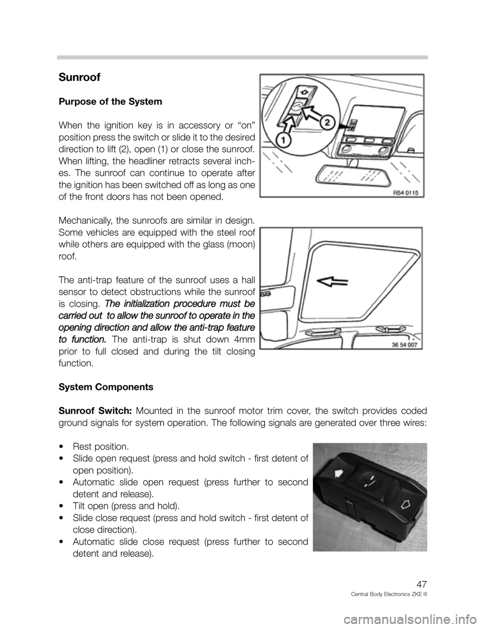
When the ignition key is in accessory or “on”
position press the switch or slide it to the desired
direction to lift (2), open (1) or close the sunroof.
When lifting, the headliner retracts several inch-
es. The sunroof can continue to operate after
the ignition has been switched off as long as one
of the front doors has not been opened.
Mechanically, the sunroofs are similar in design.
Some vehicles are equipped with the steel roof
while others are equipped with the glass (moon)
roof.
The anti-trap feature of the sunroof uses a hall
sensor to detect obstructions while the sunroof
is closing. The initialization procedure must be
carried out to allow the sunroof to operate in the
opening direction and allow the anti-trap feature
to function.
The anti-trap is shut down 4mm
prior to full closed and during the tilt closing
function.
System Components
Sunroof Switch:Mounted in the sunroof motor trim cover, the switch provides coded
ground signals for system operation. The following signals are generated over three wires:
• Rest position.
• Slide open request (press and hold switch - first detent of
open position).
• Automatic slide open request (press further to second
detent and release).
• Tilt open (press and hold).
• Slide close request (press and hold switch - first detent of
close direction).
• Automatic slide close request (press further to second
detent and release).
47
Central Body Electronics ZKE III
Page 50 of 80
Workshop Hints
SHD Self Diagnosis
The SHD monitors operation and stores fault codes if a defect is determined. The SHD
monitors the following conditions:
• SHD motor relays:The relays are checked for sticking contacts (plausibility) and non
functional contacts.
• Hall effect position sensors:The SHD must detect a pulse frequency from the hall
effect sensor(s) during operation.
• Sunroof Switch: The SHD monitors the signal plausibility of the coded signaling from
the sunroof switch.
Sunroof Fault Response Characteristics
If a fault occurs with any of these functions, the SHD responds as follows:
• Overrides the end run detection.
• Switches the motor off if the relay contacts stick for more than 500 ms.
• Switches the motor off if pulses are not received.
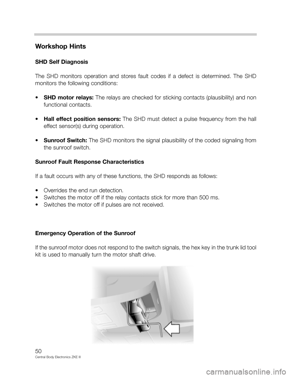
Emergency Operation of the Sunroof
If the sunroof motor does not respond to the switch signals, the hex key in the trunk lid tool
kit is used to manually turn the motor shaft drive.
50
Central Body Electronics ZKE III
Page 63 of 80
Passenger’s Seat (without memory)
Principle of Operation
The passenger seat control switch is purely a mechanical switching module that activates
the passenger seat motors without position monitoring capabilities. Due to the limited op-
eration requirements, the passenger seat control switch is not equipped with on board
diagnostics.
The Passenger Seat control switch is equipped with an overload protection function. If
excessive amperage is drawn due to a defective motor or a switch is stuck driving a motor
to the end limit, the function activates opening the motor control circuit.
Passenger Seat Motors: Each motor is individually controlled by the Seat Control Switch.
Each position motor is connected to the seat position switch by a two wire circuit provid-
ing motor activation in both directions (no position recognition).
Passenger Seat Adjustment: Operation of the passenger seat is always possible regard-
less of the ignition key position. Moving a position switch operates a the motor control con-
tacts directly, the switch applies voltage and ground path directly to operate the motor.
Reversing the switch simply changes the motor polarity. More than one passenger seat
motor can be run simultaneously.
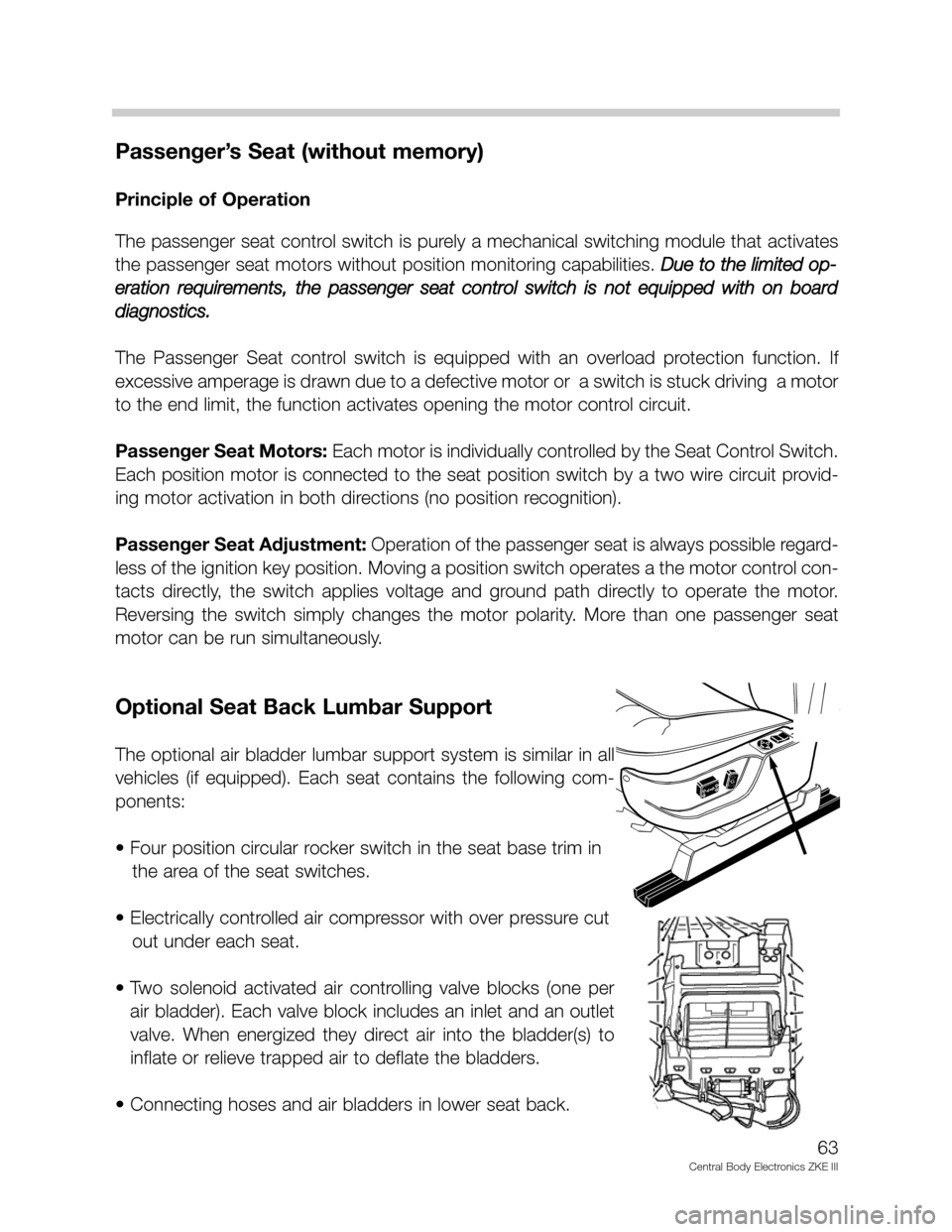
Optional Seat Back Lumbar Support
The optional air bladder lumbar support system is similar in all
vehicles (if equipped). Each seat contains the following com-
ponents:
• Four position circular rocker switch in the seat base trim in
the area of the seat switches.
• Electrically controlled air compressor with over pressure cut
out under each seat.
• Two solenoid activated air controlling valve blocks (one per
air bladder). Each valve block includes an inlet and an outlet
valve. When energized they direct air into the bladder(s) to
inflate or relieve trapped air to deflate the bladders.
• Connecting hoses and air bladders in lower seat back.
63
Central Body Electronics ZKE III
Page 64 of 80
Principle of Operation
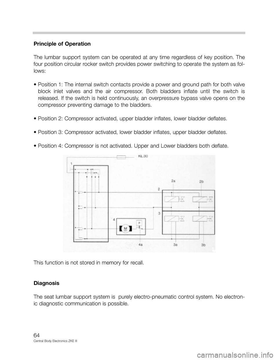
The lumbar support system can be operated at any time regardless of key position. The
four position circular rocker switch provides power switching to operate the system as fol-
lows:
• Position 1: The internal switch contacts provide a power and ground path for both valve
block inlet valves and the air compressor. Both bladders inflate until the switch is
released. If the switch is held continuously, an overpressure bypass valve opens on the
compressor preventing damage to the bladders.
• Position 2: Compressor activated, upper bladder inflates, lower bladder deflates.
• Position 3: Compressor activated, lower bladder inflates, upper bladder deflates.
• Position 4: Compressor is not activated. Upper and Lower bladders both deflate.
This function is not stored in memory for recall.
Diagnosis
The seat lumbar support system is purely electro-pneumatic control system. No electron-
ic diagnostic communication is possible.
64
Central Body Electronics ZKE III
Page 76 of 80
Sleep Mode
To lower the constant battery draw when the vehicle is parked, the complete ZKE system
will go into the “Sleep Mode” 16 minutes after the ignition has been switched off and no
further ZKE function is active.
For example, the approximate E39 (528i) Battery draw is:
• Ignition switch off = approx 750 mA.
• One minute after = approx. 560 mA.
• After 16 minutes (sleep mode) = approx. 18 mA.
All modules in the ZKE system will go into the sleep mode. The P-Bus remains active, how-
ever no data transfer takes place until a wake-up request is received. The general module,
door modules or keyless remote module can wake the system up and put the ZKE back
on line. The K-Bus is active (high) in the sleep mode.
Sleep Mode Criteria:
KL R, KL 15 OFF and no further function activated for 16 minutes.
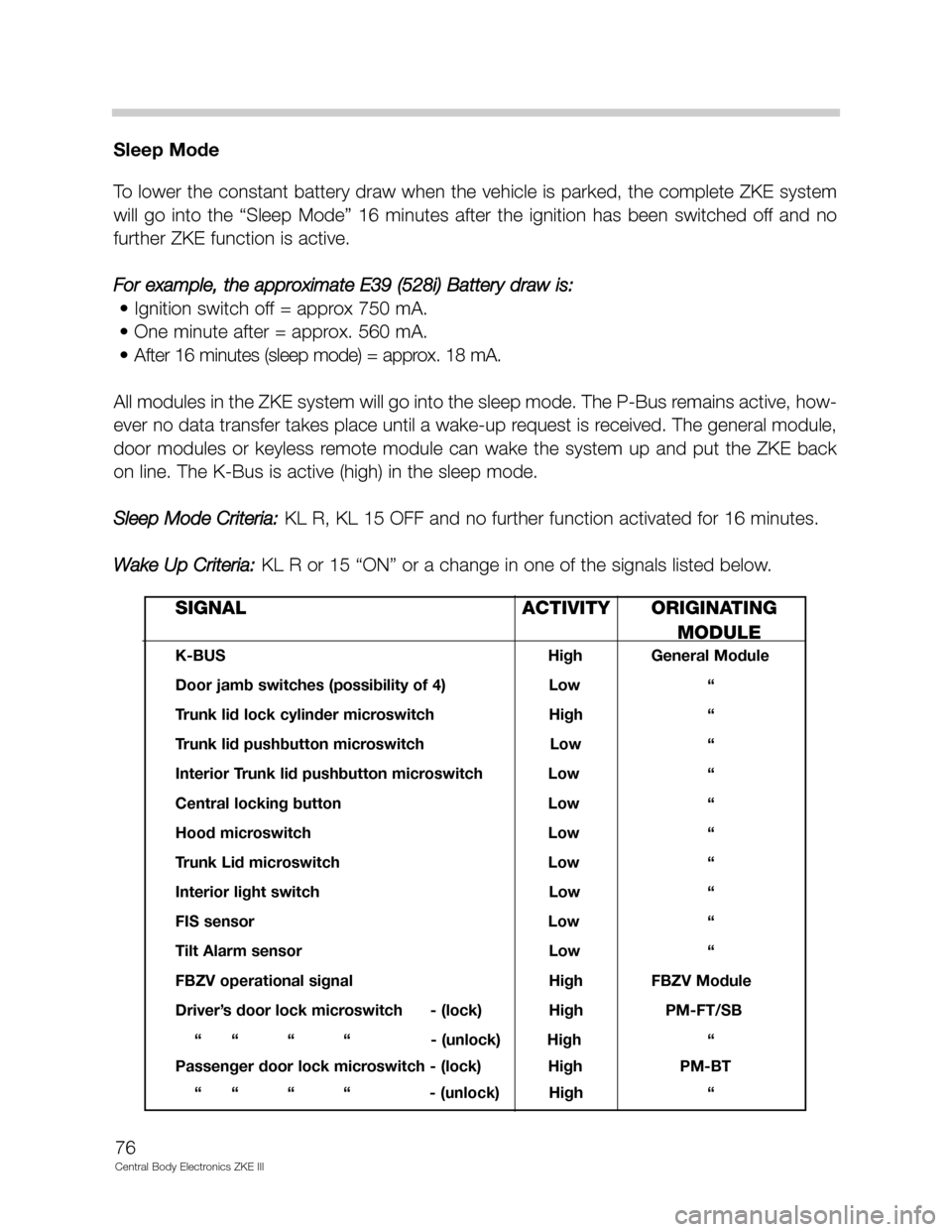
Wake Up Criteria:
KL R or 15 “ON” or a change in one of the signals listed below.
76
Central Body Electronics ZKE III
SIGNAL ACTIVITY ORIGINATING
MODULE
K-BUS High General Module
Door jamb switches (possibility of 4) Low “
Trunk lid lock cylinder microswitch High “
Trunk lid pushbutton microswitch Low “
Interior Trunk lid pushbutton microswitch Low “
Central locking button Low “
Hood microswitch Low “
Trunk Lid microswitch Low “
Interior light switch Low “
FIS sensor Low “
Tilt Alarm sensor Low “
FBZV operational signal High FBZV Module
Driver’s door lock microswitch - (lock) High PM-FT/SB
“ “ “ “ - (unlock) High “
Passenger door lock microswitch - (lock) High PM-BT
“ “ “ “ - (unlock) High “
Page 79 of 80

Review Questions
1. List the functions directly controlled by the GM III._______________________________
__________________________________________________________________________
__________________________________________________________________________
__________________________________________________________________________
2. How does the GM III communicate with other control modules?__________________
_________________________________________________________________________
_________________________________________________________________________
3. What effect does road speed have on the wiper system? What effect does it have on
an AIC equipped vehicle? Where does the road speed come from?_______________
_________________________________________________________________________
_________________________________________________________________________
_________________________________________________________________________
4. How does the GM III recognize the key position from the drivers door?____________
_________________________________________________________________________
_________________________________________________________________________
5. Describe the procedure used by the GM III to recognize an FZV key. Can the GM
differentiate between different keys? How many can it recognize?________________
_________________________________________________________________________
_________________________________________________________________________
_________________________________________________________________________
_________________________________________________________________________
6. What “convenience” features are available from the FZV key?____________________
_________________________________________________________________________
_________________________________________________________________________
7. Describe what happens when the GM receives the crash signal from the MRS.
_________________________________________________________________________
_________________________________________________________________________
_________________________________________________________________________
8. Why does the SHD (sunroof) module require initialization but the windows do not?
_________________________________________________________________________
_________________________________________________________________________
79
Central Body Electronics ZKE III