ECU BMW 550I SEDAN 2011 User Guide
[x] Cancel search | Manufacturer: BMW, Model Year: 2011, Model line: 550I SEDAN, Model: BMW 550I SEDAN 2011Pages: 304, PDF Size: 10.18 MB
Page 65 of 304
Automatic transmission with
Steptronic*
Transmission positions
D Drive, automatic position
Position for normal vehicle operation. All for‐
ward gears are available.
R is Reverse
Select only when the vehicle is stationary.
N is Neutral
Use in automatic car washes, for example. The
vehicle can roll.
When the ignition is switched off, refer to
page
58, position P is engaged automatically.
P Park
Select only when the vehicle is stationary. The
drive wheels are blocked.
P is engaged automatically:
▷ After the engine is switched off, if the car is
in
radio ready state, refer to page 58, or if the
ignition is switched off, refer to page 58, and
if position R or D is engaged.
▷ If the ignition is switched off and position N
is engaged.
▷ If the safety belt is unbuckled, the driver's
door is opened, and the brake pedal is not
pressed while the vehicle is stationary and
transmission position R or D is engaged.
Kickdown
Kickdown is used to achieve maximum driving
performance. Press on the accelerator beyond
the resistance point at the full throttle position.
Engaging the transmission position
▷ Transmission position P can only be disen‐
gaged
if the engine is running and the brake
pedal is pressed.
▷ With the vehicle stationary, press on the
brake pedal before shifting out of P or N; otherwise, the shift command will not be
executed: shift lock.
Depress
the brake until you start driv‐
ing
To prevent the vehicle from creeping after
you select a driving position, maintain pres‐
sure on the brake pedal until you are ready
to start.◀ Engaging D, R and N
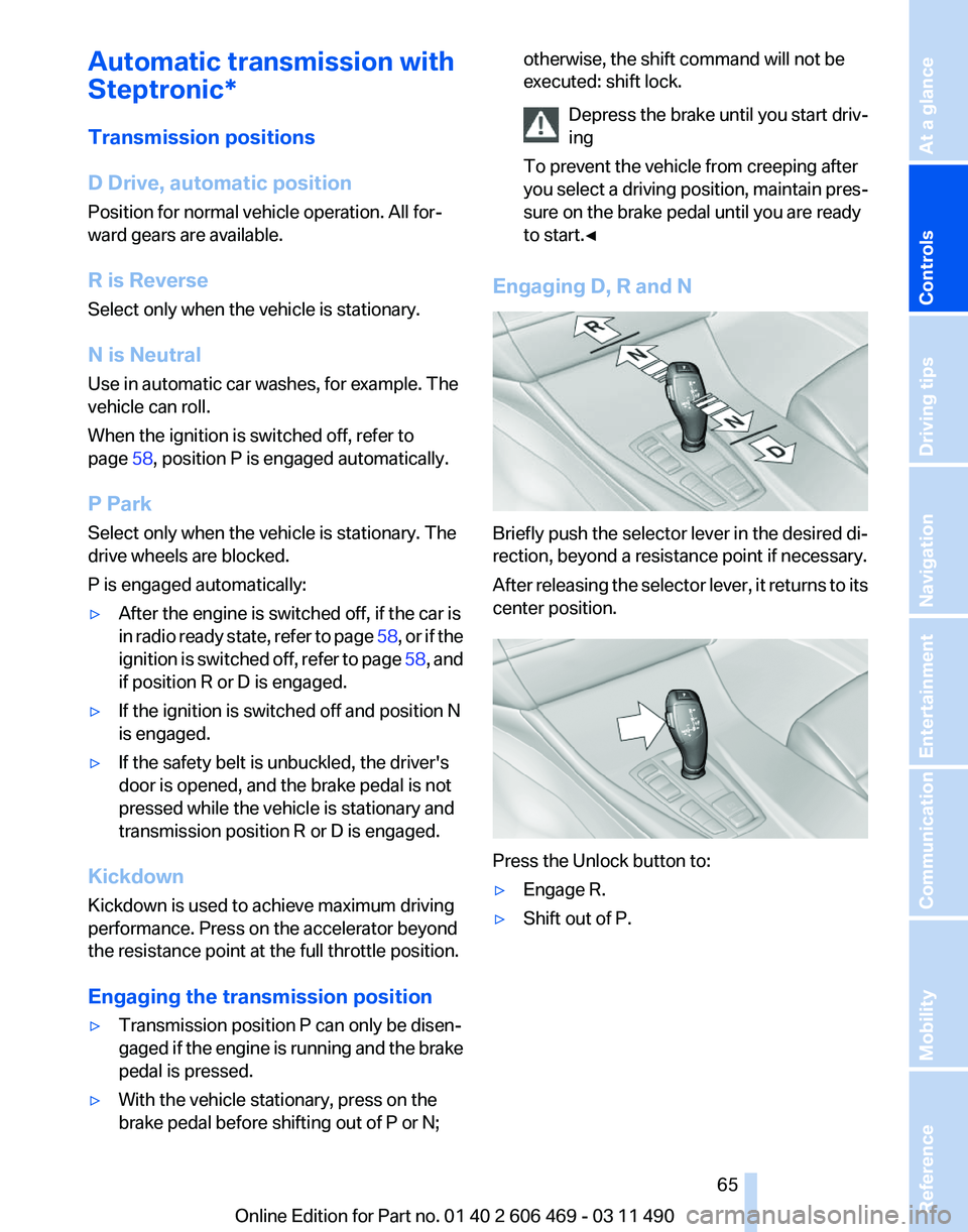
Briefly push the selector lever in the desired di‐
rection, beyond a resistance point if necessary.
After
releasing the selector lever, it returns to its
center position. Press the Unlock button to:
▷
Engage R.
▷ Shift out of P.
Seite 65
65Online Edition for Part no. 01 40 2 606 469 - 03 11 490
Reference Mobility Communication Entertainment Navigation Driving tips
Controls At a glance
Page 72 of 304
▷ "Service request"
Contact the service partner.
▷ "Roadside Assistance"
Contact Roadside Assistance.
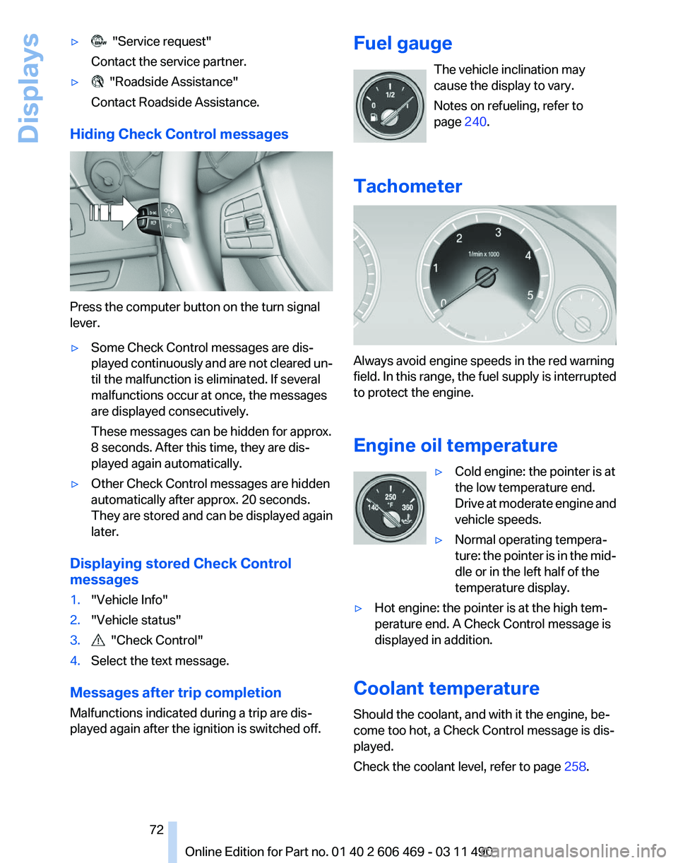
Hiding Check Control messages Press the computer button on the turn signal
lever.
▷
Some Check Control messages are dis‐
played
continuously and are not cleared un‐
til the malfunction is eliminated. If several
malfunctions occur at once, the messages
are displayed consecutively.
These messages can be hidden for approx.
8 seconds. After this time, they are dis‐
played again automatically.
▷ Other Check Control messages are hidden
automatically after approx. 20 seconds.
They
are stored and can be displayed again
later.
Displaying stored Check Control
messages
1. "Vehicle Info"
2. "Vehicle status"
3. "Check Control"
4. Select the text message.
Messages after trip completion
Malfunctions indicated during a trip are dis‐
played again after the ignition is switched off. Fuel gauge
The vehicle inclination may
cause the display to vary.
Notes on refueling, refer to
page 240.
Tachometer Always avoid engine speeds in the red warning
field.
In this range, the fuel supply is interrupted
to protect the engine.
Engine oil temperature
▷Cold engine: the pointer is at
the low temperature end.
Drive
at moderate engine and
vehicle speeds.
▷ Normal operating tempera‐
ture:
the pointer is in the mid‐
dle or in the left half of the
temperature display.
▷ Hot engine: the pointer is at the high tem‐
perature end. A Check Control message is
displayed in addition.
Coolant temperature
Should the coolant, and with it the engine, be‐
come too hot, a Check Control message is dis‐
played.
Check the coolant level, refer to page 258. Seite 72
72 Online Edition for Part no. 01 40 2 606 469 - 03 11 490
Displays
Page 104 of 304
Reduce distance
Press the button repeatedly until the
desired distance is set.
The
selected distance, refer to page 105, is dis‐
played in the instrument cluster.
Increase distance
Press the button repeatedly until the
desired distance is set.
The selected distance, refer to page 105, is dis‐
played in the instrument cluster.
Calling up the desired speed and
distance
While driving
Press the button with the system
switched on.
In the following cases, the stored speed value is
deleted and cannot be called up again:
▷ When the system is switched off.
▷ When the ignition is switched off.
While standing Before leaving the vehicle, secure it
against rolling.
Before leaving the vehicle with the engine run‐
ning, engage position P of the automatic trans‐
mission
and apply the parking brake. Otherwise,
the vehicle may begin to roll.◀
The system brought the vehicle to a complete
standstill.
▷ Green mark in the speedometer during a
brief idle phase:
The vehicle ahead of you drives away while
the mark is green: your vehicle accelerates
without anything having to be done.
▷ Switch to orange of the mark in the speed‐
ometer after approx. 2 sec.:
The
vehicle ahead of you drives away, while
the mark is orange: in order to accelerate,
briefly press the accelerator or press the
RES button or SET button. Rolling bars in the distance indicator mean that
the vehicle ahead of you has driven off.
You actively braked your vehicle to a halt by
pressing on the brake pedal and it is standing
behind another vehicle:
1.
Press the button to call up a stored
desired speed.
2. Release the brake pedal.
3. Press on the accelerator briefly, or press the
RES button or the rocker switch when the
vehicle ahead of you drives away.
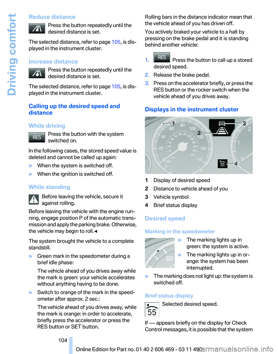
Displays in the instrument cluster 1
Display of desired speed
2 Distance to vehicle ahead of you
3 Vehicle symbol
4 Brief status display
Desired speed
Marking in the speedometer ▷The marking lights up in
green: the system is active.
▷ The marking lights up in or‐
ange: the system has been
interrupted.
▷ The marking does not light up: the system is
switched off.
Brief status display Selected desired speed.
If --- appears briefly on the display for Check
Control
messages, it is possible that the system Seite 104
104 Online Edition for Part no. 01 40 2 606 469 - 03 11 490
Driving comfort
Page 108 of 304
Collision warning with
braking function*
The concept
The system issues a two-phase warning of a
danger of collision at speeds above approx.
10 mph/15 km/h.
The collision warning is available even if cruise
control has been deactivated.
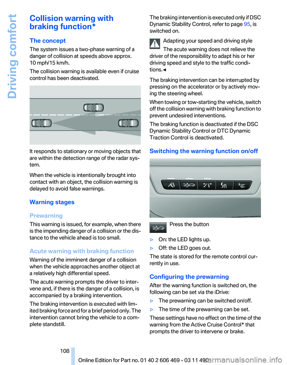
It responds to stationary or moving objects that
are within the detection range of the radar sys‐
tem.
When the vehicle is intentionally brought into
contact with an object, the collision warning is
delayed to avoid false warnings.
Warning stages
Prewarning
This
warning is issued, for example, when there
is the impending danger of a collision or the dis‐
tance to the vehicle ahead is too small.
Acute warning with braking function
Warning of the imminent danger of a collision
when the vehicle approaches another object at
a relatively high differential speed.
The acute warning prompts the driver to inter‐
vene and, if there is the danger of a collision, is
accompanied by a braking intervention.
The braking intervention is executed with lim‐
ited braking force and for a brief period only. The
intervention cannot bring the vehicle to a com‐
plete standstill. The braking intervention is executed only if DSC
Dynamic Stability Control, refer to page
95, is
switched on.
Adapting your speed and driving style
The acute warning does not relieve the
driver of the responsibility to adapt his or her
driving speed and style to the traffic condi‐
tions.◀
The braking intervention can be interrupted by
pressing on the accelerator or by actively mov‐
ing the steering wheel.
When
towing or tow-starting the vehicle, switch
off the collision warning with braking function to
prevent undesired interventions.
The braking function is deactivated if the DSC
Dynamic Stability Control or DTC Dynamic
Traction Control is deactivated.
Switching the warning function on/off Press the button
▷ On: the LED lights up.
▷ Off: the LED goes out.
The state is stored for the remote control cur‐
rently in use.
Configuring the prewarning
After the warning function is switched on, the
following can be set via the iDrive:
▷ The prewarning can be switched on/off.
▷ The time of the prewarning can be set.
These settings have no effect on the time of the
warning from the Active Cruise Control* that
prompts the driver to intervene or brake. Seite 108
108 Online Edition for Part no. 01 40 2 606 469 - 03 11 490
Driving comfort
Page 123 of 304
If pedestrian detection is not available, a symbol
is displayed in the heat image.
This symbol disappears when the function be‐
comes available again.
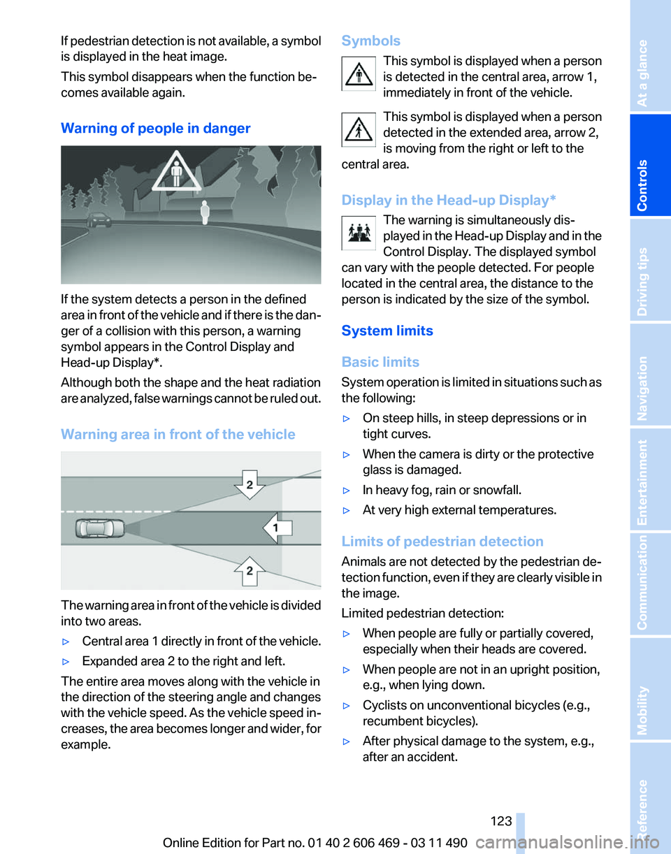
Warning of people in danger
If the system detects a person in the defined
area
in front of the vehicle and if there is the dan‐
ger of a collision with this person, a warning
symbol appears in the Control Display and
Head-up Display*.
Although both the shape and the heat radiation
are analyzed, false warnings cannot be ruled out.
Warning area in front of the vehicle The warning area in front of the vehicle is divided
into two areas.
▷
Central area 1 directly in front of the vehicle.
▷ Expanded area 2 to the right and left.
The entire area moves along with the vehicle in
the direction of the steering angle and changes
with
the vehicle speed. As the vehicle speed in‐
creases, the area becomes longer and wider, for
example. Symbols
This
symbol is displayed when a person
is detected in the central area, arrow 1,
immediately in front of the vehicle.
This symbol is displayed when a person
detected in the extended area, arrow 2,
is moving from the right or left to the
central area.
Display in the Head-up Display*
The warning is simultaneously dis‐
played in the Head-up Display and in the
Control Display. The displayed symbol
can vary with the people detected. For people
located in the central area, the distance to the
person is indicated by the size of the symbol.
System limits
Basic limits
System operation is limited in situations such as
the following:
▷ On steep hills, in steep depressions or in
tight curves.
▷ When the camera is dirty or the protective
glass is damaged.
▷ In heavy fog, rain or snowfall.
▷ At very high external temperatures.
Limits of pedestrian detection
Animals are not detected by the pedestrian de‐
tection
function, even if they are clearly visible in
the image.
Limited pedestrian detection:
▷ When people are fully or partially covered,
especially when their heads are covered.
▷ When people are not in an upright position,
e.g., when lying down.
▷ Cyclists on unconventional bicycles (e.g.,
recumbent bicycles).
▷ After physical damage to the system, e.g.,
after an accident. Seite 123
123Online Edition for Part no. 01 40 2 606 469 - 03 11 490
Reference Mobility Communication Entertainment Navigation Driving tips
Controls At a glance
Page 132 of 304
Interior equipment
Integrated universal remote
control*
The concept
This system can replace up to three different
hand-held transmitters for various types of re‐
mote-controlled equipment, such as garage
doors or lighting systems.
The hand-held transmitter signal can be pro‐
grammed on one of the three memory buttons.
The
corresponding device can then be operated
using the programmed memory button.
The LED indicates that a signal is being trans‐
mitted.
When selling the vehicle, delete the stored pro‐
grams for security reasons.
During programming
During programming and before activat‐
ing a device using the universal remote control,
ensure that there are no people, animals, or ob‐
jects in the range of movement of the remote-
controlled device; otherwise, there is a risk of
injury or damage.
Also follow the safety instructions of the hand-
held transmitter.◀
Compatibility
If this symbol is printed on the packaging
or in the instructions of the hand-held
transmitter, the remote-controlled de‐
vice is generally compatible with the universal
remote control.
If you have any questions, please contact:
▷ Your service center.
▷ www.homelink.com on the Internet. Programming
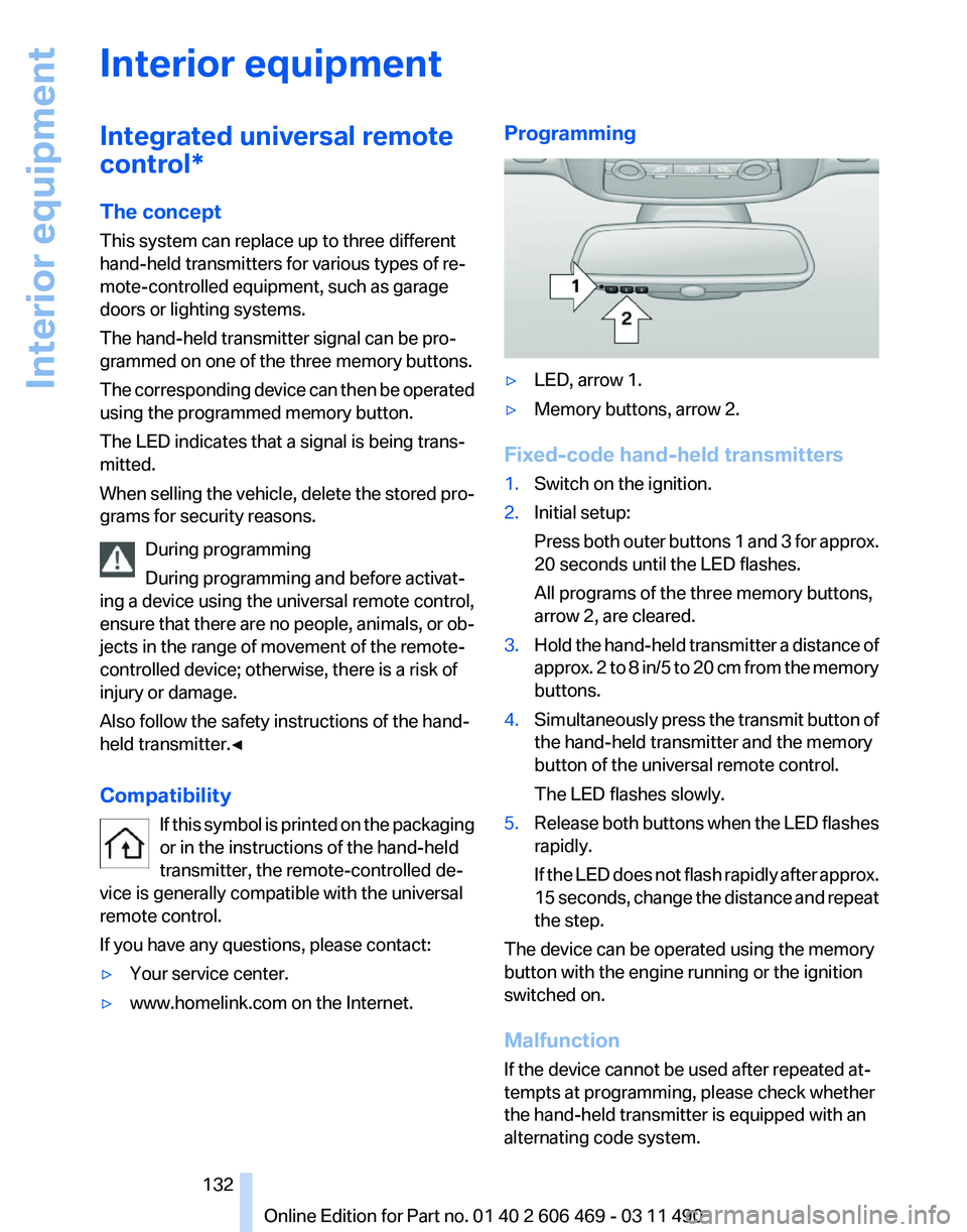
▷
LED, arrow 1.
▷ Memory buttons, arrow 2.
Fixed-code hand-held transmitters
1. Switch on the ignition.
2. Initial setup:
Press
both outer buttons 1 and 3 for approx.
20 seconds until the LED flashes.
All programs of the three memory buttons,
arrow 2, are cleared.
3. Hold the hand-held transmitter a distance of
approx.
2 to 8 in/5 to 20 cm from the memory
buttons.
4. Simultaneously press the transmit button of
the hand-held transmitter and the memory
button of the universal remote control.
The LED flashes slowly.
5. Release both buttons when the LED flashes
rapidly.
If
the LED does not flash rapidly after approx.
15 seconds, change the distance and repeat
the step.
The device can be operated using the memory
button with the engine running or the ignition
switched on.
Malfunction
If the device cannot be used after repeated at‐
tempts at programming, please check whether
the hand-held transmitter is equipped with an
alternating code system.
Seite 132
132 Online Edition for Part no. 01 40 2 606 469 - 03 11 490
Interior equipment
Page 137 of 304
Ensure that the lock is securely en‐
gaged
When
folding back the backrest, be sure that
it locks in place securely. If it is not properly
engaged, transported cargo could enter the
passenger compartment during braking or
evasive maneuvers and endanger the vehi‐
cle occupants.◀ 2.
Release the latch plate from the fixture on
the rear window shelf and insert it into the
belt
lock of the center safety belt. Make sure
you hear the latch plate engage.
To secure cargo, refer to page 149,
with nets or
draw straps, the cargo area is fitted with lashing
eyes.
Ski bag*
Capacity
The ski bag can be used to transport up to four
pairs of skis with a length of up to 6 ft/2.10 m or,
depending on the binding, up to two snow‐
boards with a length of up to 5 ft/1.60 m.
Preparing and loading the ski bag
1. Fold open the center armrest on the inside.
2. Open the inside cover and cargo area by
pressing the button. 3.
Lay out the ski bag.
4. Load the ski bag. If necessary, wrap the
sharp edges of the skis.
If
necessary, open the ski bag zipper to ease
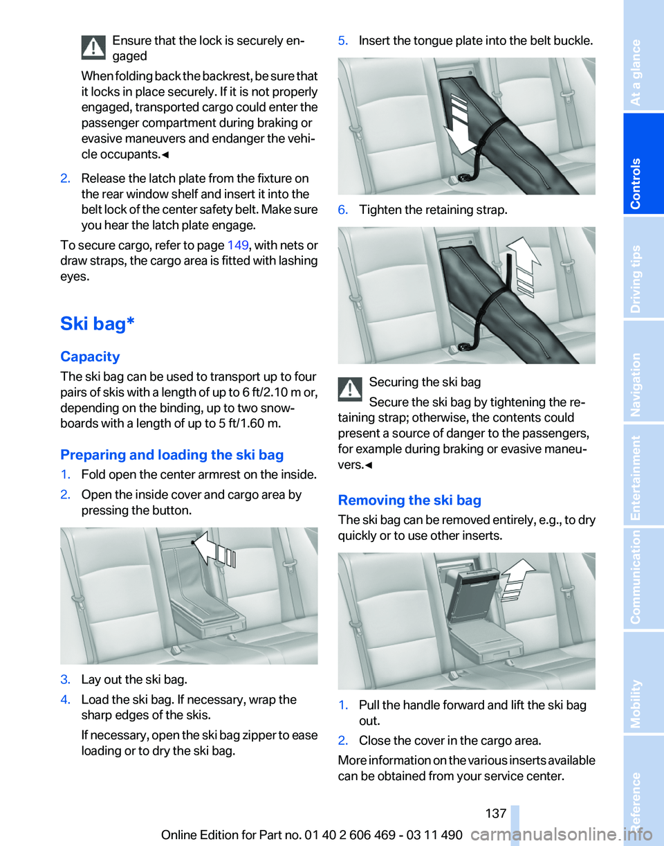
loading or to dry the ski bag. 5.
Insert the tongue plate into the belt buckle. 6.
Tighten the retaining strap. Securing the ski bag
Secure the ski bag by tightening the re‐
taining strap; otherwise, the contents could
present a source of danger to the passengers,
for example during braking or evasive maneu‐
vers.◀
Removing the ski bag
The
ski bag can be removed entirely, e.g., to dry
quickly or to use other inserts. 1.
Pull the handle forward and lift the ski bag
out.
2. Close the cover in the cargo area.
More information on the various inserts available
can be obtained from your service center. Seite 137
137Online Edition for Part no. 01 40 2 606 469 - 03 11 490
Reference Mobility Communication Entertainment Navigation Driving tips
Controls At a glance
Page 142 of 304
Light and suitable objects only
Only hang light bags or suitable objects
from
the holders. Otherwise, there is a danger of
objects flying about during braking and evasive
maneuvers.
Only transport heavy luggage in the trunk if it has
been appropriately secured.◀
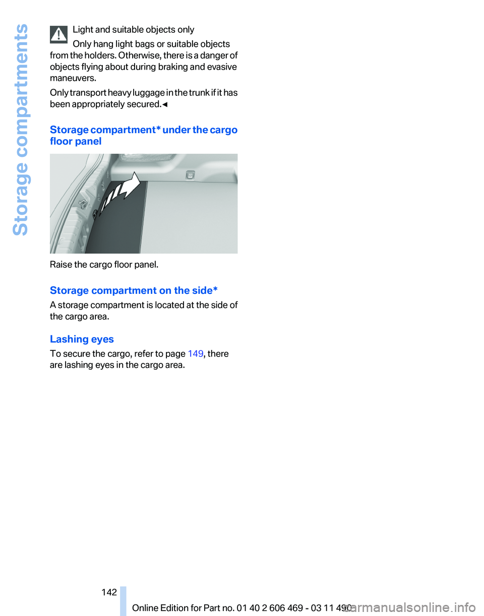
Storage compartment* under the cargo
floor panel Raise the cargo floor panel.
Storage compartment on the side
*
A storage compartment is located at the side of
the cargo area.
Lashing eyes
To secure the cargo, refer to page 149, there
are lashing eyes in the cargo area. Seite 142
142 Online Edition for Part no. 01 40 2 606 469 - 03 11 490
Storage compartments
Page 147 of 304
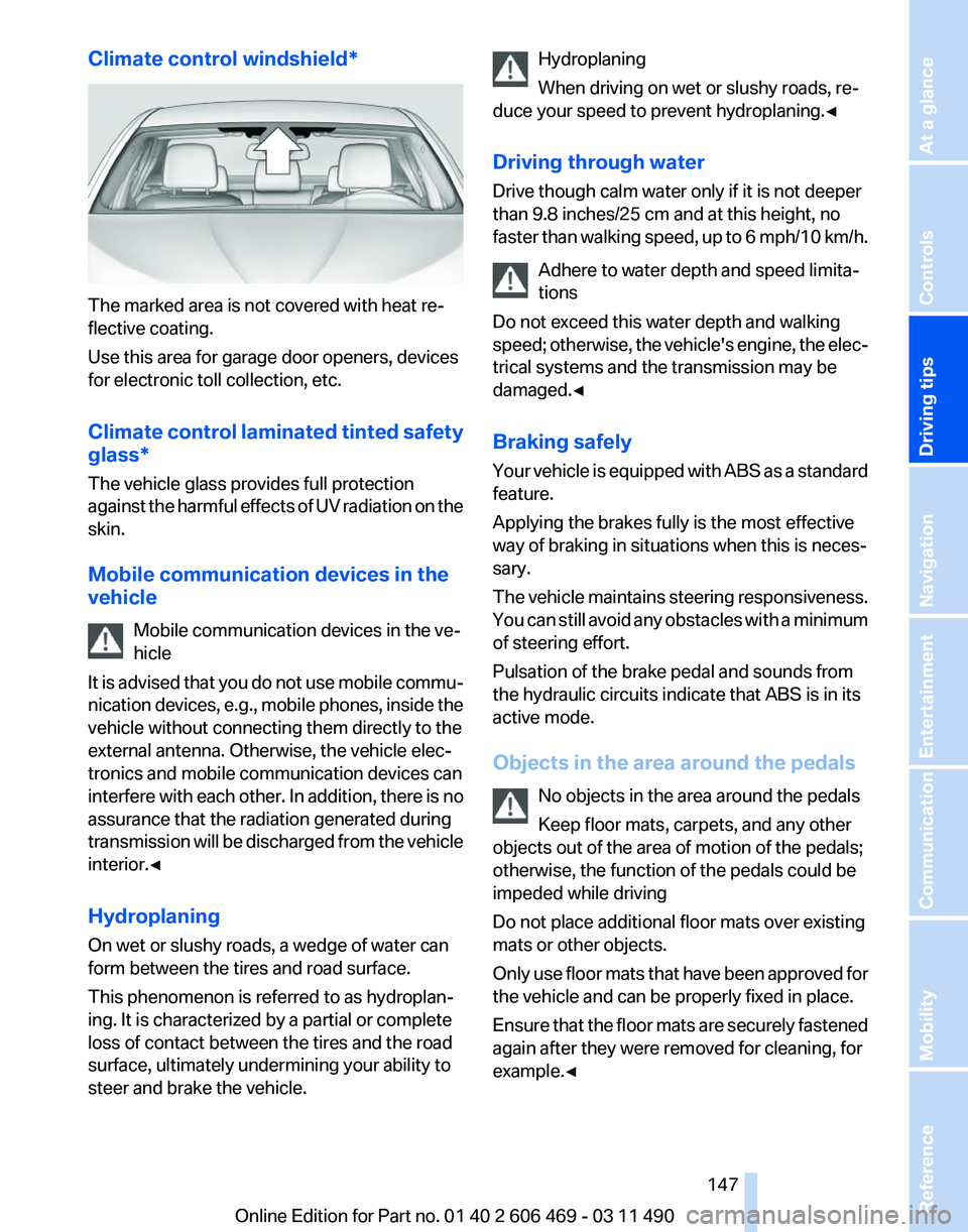
Climate control windshield*
The marked area is not covered with heat re‐
flective coating.
Use this area for garage door openers, devices
for electronic toll collection, etc.
Climate
control laminated tinted safety
glass*
The vehicle glass provides full protection
against the harmful effects of UV radiation on the
skin.
Mobile communication devices in the
vehicle
Mobile communication devices in the ve‐
hicle
It is advised that you do not use mobile commu‐
nication devices, e.g., mobile phones, inside the
vehicle without connecting them directly to the
external antenna. Otherwise, the vehicle elec‐
tronics and mobile communication devices can
interfere with each other. In addition, there is no
assurance that the radiation generated during
transmission will be discharged from the vehicle
interior.◀
Hydroplaning
On wet or slushy roads, a wedge of water can
form between the tires and road surface.
This phenomenon is referred to as hydroplan‐
ing. It is characterized by a partial or complete
loss of contact between the tires and the road
surface, ultimately undermining your ability to
steer and brake the vehicle. Hydroplaning
When driving on wet or slushy roads, re‐
duce your speed to prevent hydroplaning.
◀
Driving through water
Drive though calm water only if it is not deeper
than 9.8 inches/25 cm and at this height, no
faster than walking speed, up to 6 mph/10 km/h. Adhere to water depth and speed limita‐
tions
Do not exceed this water depth and walking
speed; otherwise, the vehicle's engine, the elec‐
trical systems and the transmission may be
damaged.◀
Braking safely
Your vehicle is equipped with ABS as a standard
feature.
Applying the brakes fully is the most effective
way of braking in situations when this is neces‐
sary.
The vehicle maintains steering responsiveness.
You can still avoid any obstacles with a minimum
of steering effort.
Pulsation of the brake pedal and sounds from
the hydraulic circuits indicate that ABS is in its
active mode.
Objects in the area around the pedals
No objects in the area around the pedals
Keep floor mats, carpets, and any other
objects out of the area of motion of the pedals;
otherwise, the function of the pedals could be
impeded while driving
Do not place additional floor mats over existing
mats or other objects.
Only use floor mats that have been approved for
the vehicle and can be properly fixed in place.
Ensure that the floor mats are securely fastened
again after they were removed for cleaning, for
example.◀ Seite 147
147Online Edition for Part no. 01 40 2 606 469 - 03 11 490
Reference Mobility Communication Entertainment Navigation
Driving tips Controls At a glance
Page 149 of 304
hicle and unstable driving situations may
result.
2. Determine the combined weight of the
driver and passengers that will be riding in
your vehicle.
3. Subtract the combined weight of the driver
and
passengers from XXX kilograms or YYY
pounds.
4. The resulting figure equals the available
amount
of cargo and luggage load capacity.
For example, if the YYY amount equals
1,000 lbs and there will be four 150 lbs pas‐
sengers in your vehicle, the amount of avail‐
able cargo and luggage load capacity is
400 lbs: 1,000 lbs minus 600 lbs = 400 lbs.
5. Determine the combined weight of luggage
and
cargo being loaded on the vehicle. That
weight may not safely exceed the available
cargo and luggage load capacity calculated
in Step 4.
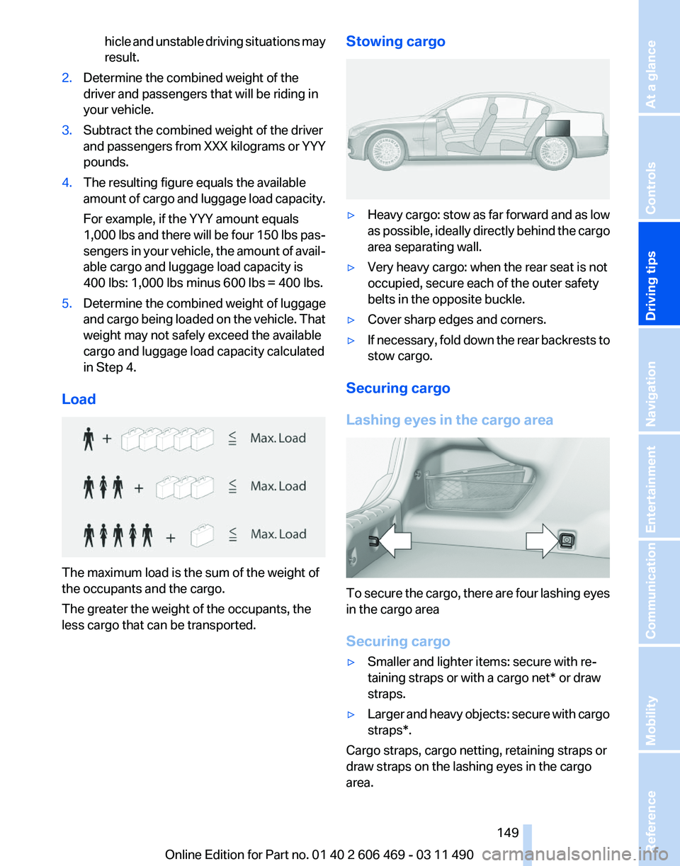
Load The maximum load is the sum of the weight of
the occupants and the cargo.
The greater the weight of the occupants, the
less cargo that can be transported. Stowing cargo ▷
Heavy cargo: stow as far forward and as low
as
possible, ideally directly behind the cargo
area separating wall.
▷ Very heavy cargo: when the rear seat is not
occupied, secure each of the outer safety
belts in the opposite buckle.
▷ Cover sharp edges and corners.
▷ If necessary, fold down the rear backrests to
stow cargo.
Securing cargo
Lashing eyes in the cargo area To secure the cargo, there are four lashing eyes
in the cargo area
Securing cargo
▷
Smaller and lighter items: secure with re‐
taining straps or with a
cargo net* or draw
straps.
▷ Larger and heavy objects: secure with cargo
straps*.
Cargo straps, cargo netting, retaining straps or
draw straps on the lashing eyes in the cargo
area.
Seite 149
149Online Edition for Part no. 01 40 2 606 469 - 03 11 490
Reference Mobility Communication Entertainment Navigation
Driving tips Controls At a glance