automatic transmission BMW 550I XDRIVE 2011 F10 User Guide
[x] Cancel search | Manufacturer: BMW, Model Year: 2011, Model line: 550I XDRIVE, Model: BMW 550I XDRIVE 2011 F10Pages: 304, PDF Size: 10.18 MB
Page 66 of 304
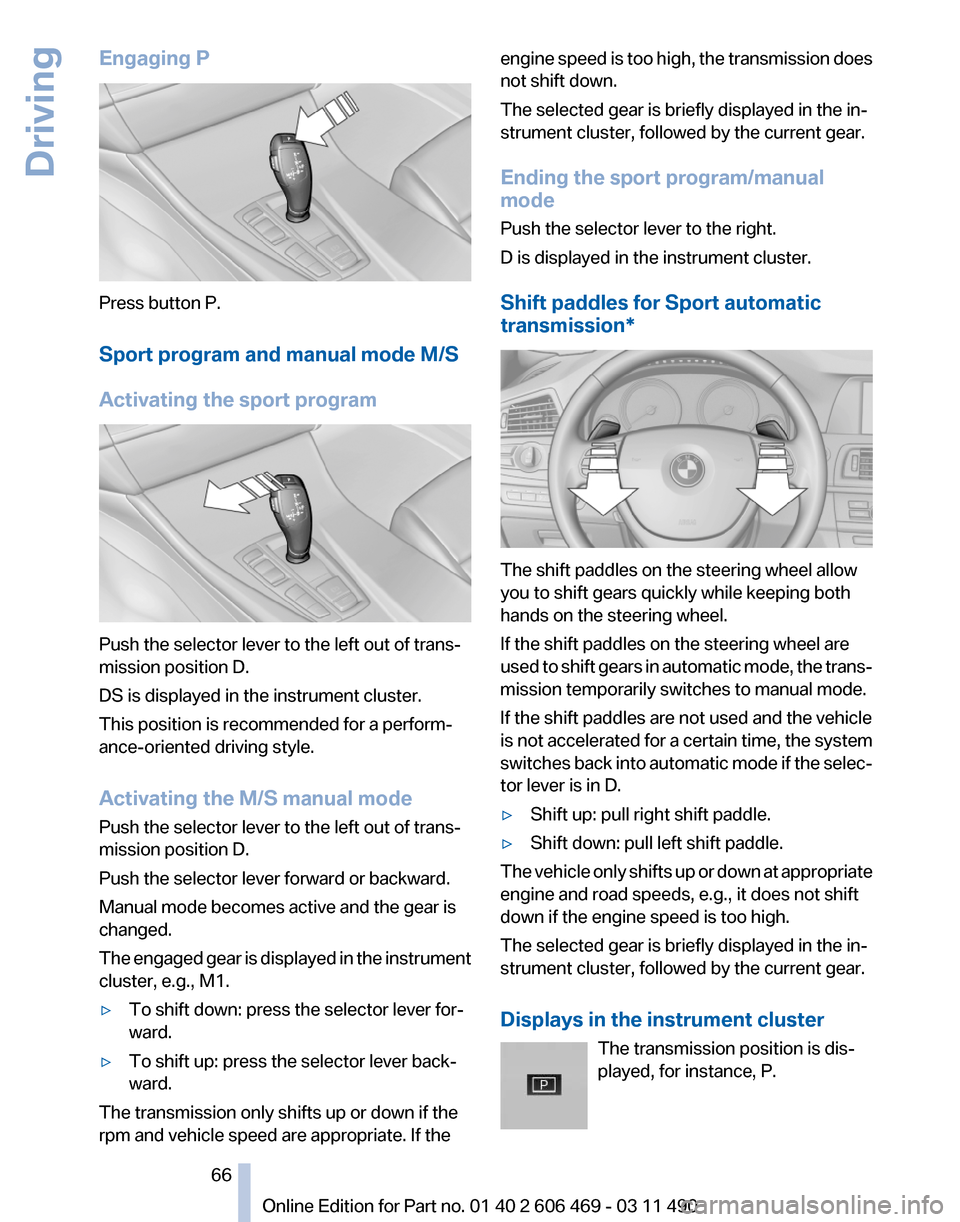
Engaging P
Press button P.
Sport program and manual mode M/S
Activating the sport program
Push the selector lever to the left out of trans‐
mission position D.
DS is displayed in the instrument cluster.
This position is recommended for a perform‐
ance-oriented driving style.
Activating the M/S manual mode
Push the selector lever to the left out of trans‐
mission position D.
Push the selector lever forward or backward.
Manual mode becomes active and the gear is
changed.
The
engaged gear is displayed in the instrument
cluster, e.g., M1.
▷ To shift down: press the selector lever for‐
ward.
▷ To shift up: press the selector lever back‐
ward.
The transmission only shifts up or down if the
rpm and vehicle speed are appropriate. If the engine speed is too high, the transmission does
not shift down.
The selected gear is briefly displayed in the in‐
strument cluster, followed by the current gear.
Ending the sport program/manual
mode
Push the selector lever to the right.
D is displayed in the instrument cluster.
Shift paddles for Sport automatic
transmission*
The shift paddles on the steering wheel allow
you to shift gears quickly while keeping both
hands on the steering wheel.
If the shift paddles on the steering wheel are
used
to shift gears in automatic mode, the trans‐
mission temporarily switches to manual mode.
If the shift paddles are not used and the vehicle
is not accelerated for a certain time, the system
switches back into automatic mode if the selec‐
tor lever is in D.
▷ Shift up: pull right shift paddle.
▷ Shift down: pull left shift paddle.
The vehicle only shifts up or down at appropriate
engine and road speeds, e.g., it does not shift
down if the engine speed is too high.
The selected gear is briefly displayed in the in‐
strument cluster, followed by the current gear.
Displays in the instrument cluster The transmission position is dis‐
played, for instance, P. Seite 66
66 Online Edition for Part no. 01 40 2 606 469 - 03 11 490
Driving
Page 103 of 304
The displays go out. The stored desired speed
and distance are deleted.
Interrupting
When active, press the button.
If
interrupting the system while stationary, press
on the brake pedal at the same time.
The system is automatically interrupted if:
▷ The brakes are applied.
▷ The clutch pedal is depressed.
▷ Transmission position D is disengaged.
▷ DTC Dynamic Traction Control is activated
or DSC is deactivated.
▷ DSC is actively controlling stability.
▷ The safety belt and the driver's door are
opened when the vehicle is standing.
▷ The system has not detected objects for an
extended
period, e.g., on a road with very lit‐
tle traffic without road edge line markings.
▷ Radar sensor is soiled.
Maintaining/storing the speed Press the button*.
When the system is switched on, the current
speed is maintained and stored as the desired
speed.
It is displayed in the speedometer and briefly
displayed in the instrument cluster, Displays in
the instrument cluster, refer to page 104.
When cruise control is maintained or stored,
DSC
Dynamic Stability Control is switched on, if
necessary.
Changing, maintaining, and storing the
speed
The rocker switch can be pressed while the sys‐
tem is interrupted to maintain and store the cur‐
rent speed. DSC Dynamic Stability Control is
switched on, if necessary. Adapting the desired speed
Adapt the desired speed to the road con‐
ditions
and be ready to brake at all times; other‐
wise, there is the danger of an accident occur‐
ring.◀
Speed differences
Great speed differences with vehicles
driving ahead of you, e.g., when rapidly ap‐
proaching a truck or when another vehicle
swerves into your own lane, cannot be compen‐
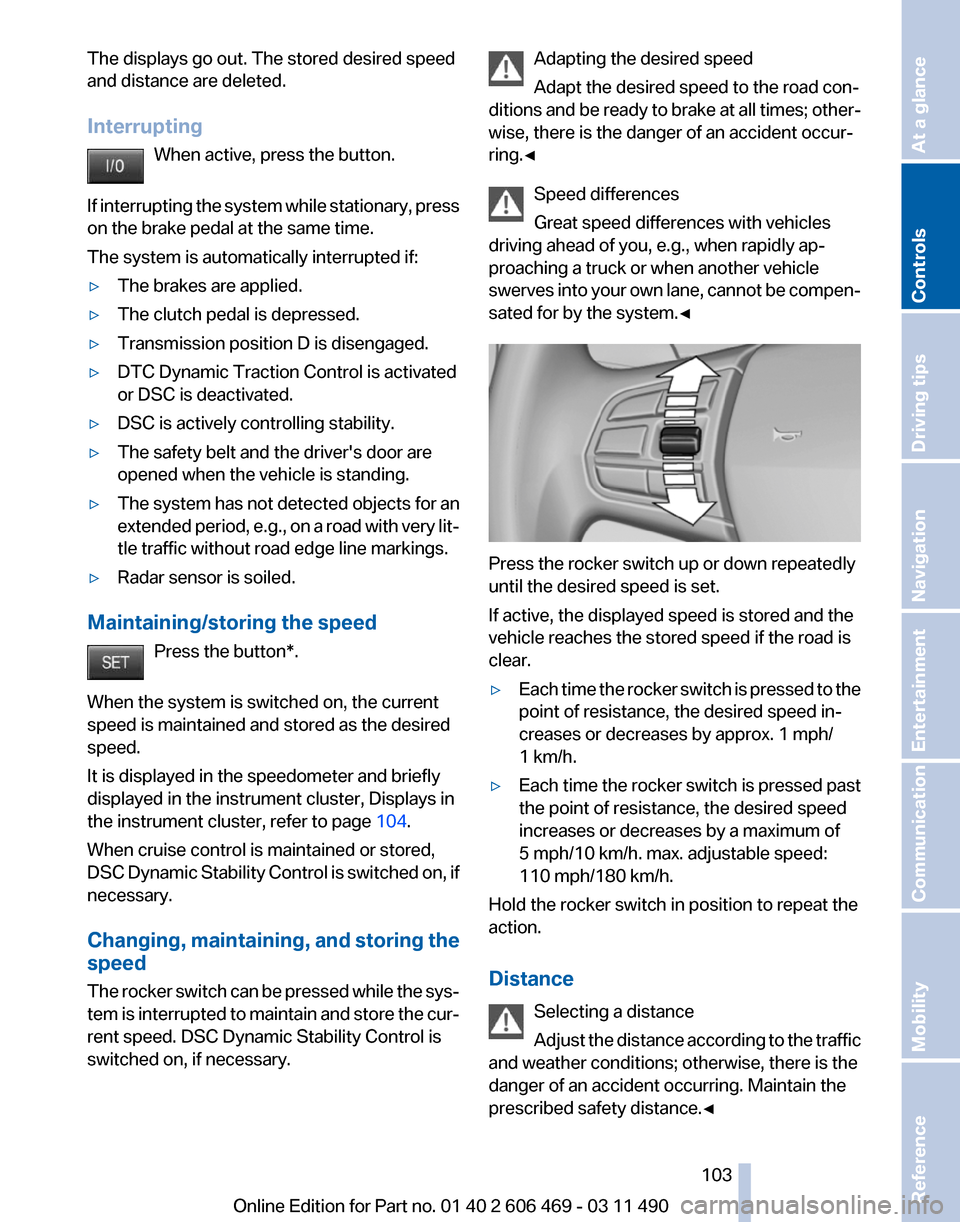
sated for by the system.◀ Press the rocker switch up or down repeatedly
until the desired speed is set.
If active, the displayed speed is stored and the
vehicle reaches the stored speed if the road is
clear.
▷
Each time the rocker switch is pressed to the
point of resistance, the desired speed in‐
creases or decreases by approx. 1 mph/
1 km/h.
▷ Each time the rocker switch is pressed past
the point of resistance, the desired speed
increases or decreases by a maximum of
5 mph/10 km/h. max. adjustable speed:
110 mph/180 km/h.
Hold the rocker switch in position to repeat the
action.
Distance
Selecting a distance
Adjust
the distance according to the traffic
and weather conditions; otherwise, there is the
danger of an accident occurring. Maintain the
prescribed safety distance.◀ Seite 103
103Online Edition for Part no. 01 40 2 606 469 - 03 11 490
Reference Mobility Communication Entertainment Navigation Driving tips
Controls At a glance
Page 110 of 304
3
Store speed*
4 Store, maintain/change speed
Switching on Press the button on the steering wheel.
The marking in the speedometer is set to the
current speed.
Cruise control can be used.
Switching off Deactivated or interrupted system
If the system is deactivated or interrupted,
actively intervene by braking and, if necessary,
with evasive maneuvers; otherwise, there is the
danger of an accident occurring.◀
Press the button.
▷ If active: press twice.
▷ If interrupted: press once.
The displays go out. The stored desired speed
is deleted.
Interrupting When active, press the button.
The system is automatically interrupted if:
▷ The brakes are applied.
▷ The clutch pedal is depressed.
▷ Transmission position D is disengaged.
▷ DTC Dynamic Traction Control is activated
or DSC is deactivated.
▷ DSC is actively controlling stability.
▷ HDC is activated.
Maintaining/storing the current speed Press the button.
When the system is switched on, the current
speed is maintained and stored as the desired
speed. It is displayed in the speedometer and briefly
displayed in the instrument cluster, Displays in
the speedometer, refer to page
111.
When cruise control is maintained or stored,
DSC
Dynamic Stability Control is switched on, if
necessary.
Change, maintain speed
The rocker switch can be pressed while inter‐
rupted to maintain and store the current speed.
Adapting the desired speed
Adapt the desired speed to the road con‐
ditions and be ready to brake at all times; other‐
wise, there is the danger of an accident occur‐
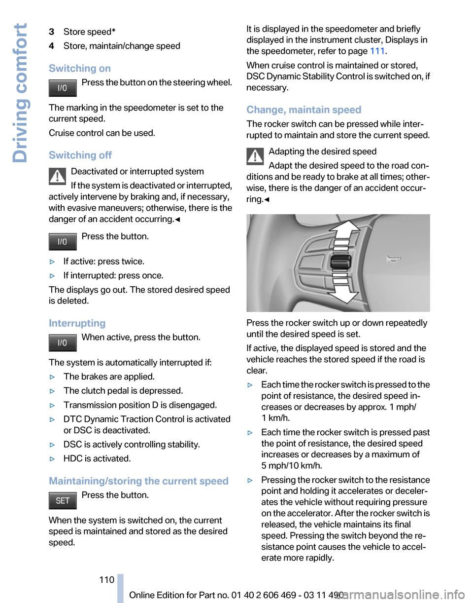
ring.◀ Press the rocker switch up or down repeatedly
until the desired speed is set.
If active, the displayed speed is stored and the
vehicle reaches the stored speed if the road is
clear.
▷
Each time the rocker switch is pressed to the
point of resistance, the desired speed in‐
creases or decreases by approx. 1 mph/
1 km/h.
▷ Each time the rocker switch is pressed past
the point of resistance, the desired speed
increases or decreases by a maximum of
5 mph/10 km/h.
▷ Pressing the rocker switch to the resistance
point and holding it accelerates or deceler‐
ates the vehicle without requiring pressure
on
the accelerator. After the rocker switch is
released, the vehicle maintains its final
speed. Pressing the switch beyond the re‐
sistance point causes the vehicle to accel‐
erate more rapidly. Seite 110
110 Online Edition for Part no. 01 40 2 606 469 - 03 11 490
Driving comfort
Page 112 of 304
Low objects already displayed, e.g., curbs, can
move
into the blind area of the sensors before or
after a continuous tone sounds.
High, protruding objects such as ledges may not
be detected.
False warnings
PDC may issue a warning under the following
conditions even though there is no obstacle
within the detection range:
▷ In heavy rain.
▷ When sensors are very dirty or covered in
ice.
▷ When sensors are covered in snow.
▷ On rough road surfaces.
▷ In large buildings with right angles and
smooth
walls, e.g., in underground garages.
▷ In heavy exhaust.
▷ Due to other ultrasound sources, e.g.,
sweeping machines, high pressure steam
cleaners or neon lights.
Switching on automatically
Select transmission position R with the engine
running.
Switching off automatically
The
system switches off and the LED goes out:
▷ After approx. 160 ft/50 m when driving for‐
ward.
▷ Above approx. 22 mph/36 km/h when driv‐
ing forward.
Switch on the system again if necessary.
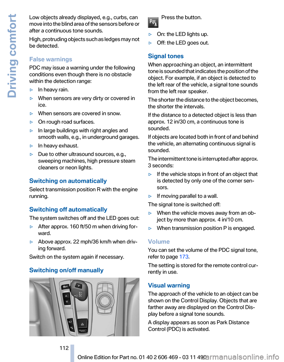
Switching on/off manually Press the button.
▷ On: the LED lights up.
▷ Off: the LED goes out.
Signal tones
When approaching an object, an intermittent
tone
is sounded that indicates the position of the
object. For example, if an object is detected to
the left rear of the vehicle, a signal tone sounds
from the left rear speaker.
The shorter the distance to the object becomes,
the shorter the intervals.
If the distance to a detected object is less than
approx. 12 in/30 cm, a continuous tone is
sounded.
If objects are located both in front of and behind
the vehicle, an alternating continuous signal is
sounded.
The intermittent tone is interrupted after approx.
3 seconds:
▷ If the vehicle stops in front of an object that
is detected by only one of the corner sen‐
sors.
▷ If moving parallel to a wall.
The signal tone is switched off:
▷ When the vehicle moves away from an ob‐
ject by more than approx. 4 in/10 cm.
▷ When transmission position P is engaged.
Volume
You can set the volume of the PDC signal tone,
refer to page 173.
The
setting is stored for the remote control cur‐
rently in use.
Visual warning
The approach of the vehicle to an object can be
shown on the Control Display. Objects that are
farther away are displayed on the Control Dis‐
play before a signal tone sounds.
A display appears as soon as Park Distance
Control (PDC) is activated. Seite 112
112 Online Edition for Part no. 01 40 2 606 469 - 03 11 490
Driving comfort
Page 114 of 304
Detection of objects
High, protruding objects such as ledges
may not be detected by the backup camera.
◀
Switching on automatically
Select transmission position R with the engine
running.
The backup camera image is displayed if the
system was switched on via the iDrive.
Switching off automatically
The system switches off and the LED goes out:
▷ After approx. 33 ft/10 m when driving for‐
ward.
▷ Above approx. 9 mph/15 km/h when driving
forward.
Switch on the system again if necessary.
Switching on/off manually Press the button.
▷ On: the LED lights up.
▷ Off: the LED goes out.
The PDC is shown on the Control Display.
Switch
on the backup camera via the iDrive, refer
to page 115.
Assistance functions
Functional requirement
▷ The backup camera is switched on.
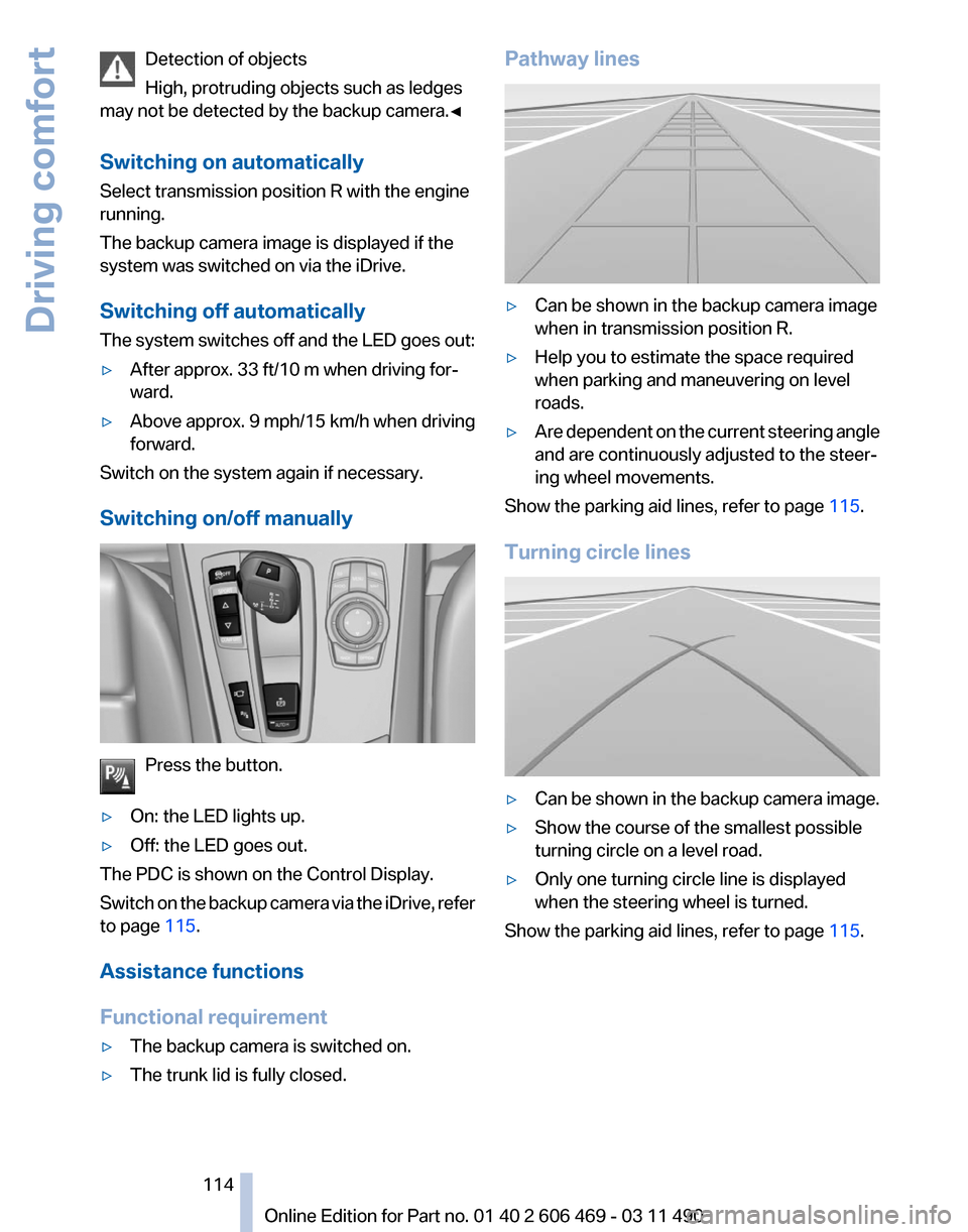
▷ The trunk lid is fully closed. Pathway lines
▷
Can be shown in the backup camera image
when in transmission position R.
▷ Help you to estimate the space required
when parking and maneuvering on level
roads.
▷ Are dependent on the current steering angle
and are continuously adjusted to the steer‐
ing wheel movements.
Show the parking aid lines, refer to page 115.
Turning circle lines ▷
Can be shown in the backup camera image.
▷ Show the course of the smallest possible
turning circle on a level road.
▷ Only one turning circle line is displayed
when the steering wheel is turned.
Show the parking aid lines, refer to page 115.
Seite 114
114 Online Edition for Part no. 01 40 2 606 469 - 03 11 490
Driving comfort
Page 116 of 304
Camera
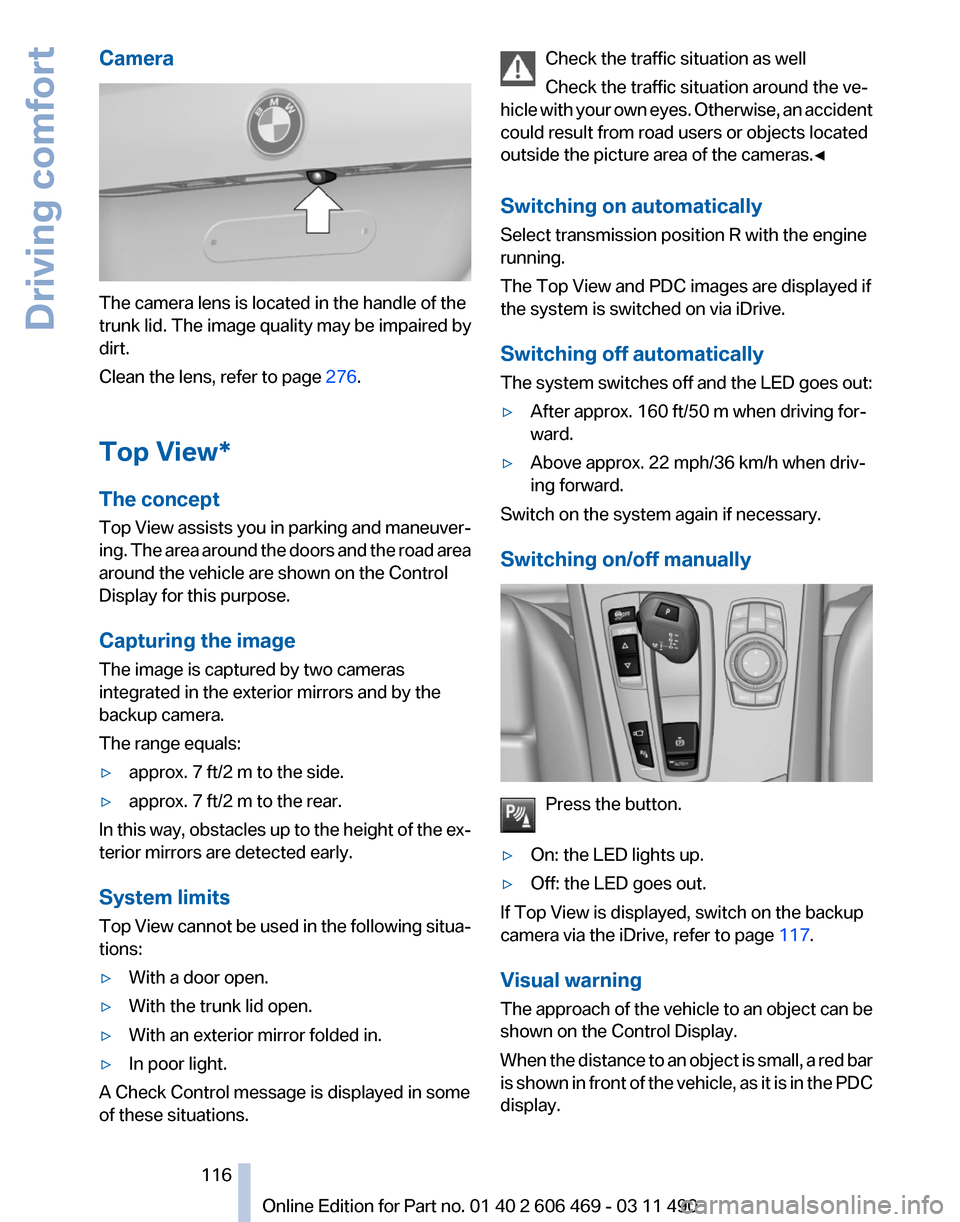
The camera lens is located in the handle of the
trunk lid. The image quality may be impaired by
dirt.
Clean the lens, refer to page
276.
Top View*
The concept
Top
View assists you in parking and maneuver‐
ing. The area around the doors and the road area
around the vehicle are shown on the Control
Display for this purpose.
Capturing the image
The image is captured by two cameras
integrated in the exterior mirrors and by the
backup camera.
The range equals:
▷ approx. 7 ft/2 m to the side.
▷ approx. 7 ft/2 m to the rear.
In this way, obstacles up to the height of the ex‐
terior mirrors are detected early.
System limits
Top
View cannot be used in the following situa‐
tions:
▷ With a door open.
▷ With the trunk lid open.
▷ With an exterior mirror folded in.
▷ In poor light.
A Check Control message is displayed in some
of these situations. Check the traffic situation as well
Check the traffic situation around the ve‐
hicle
with your own eyes. Otherwise, an accident
could result from road users or objects located
outside the picture area of the cameras.◀
Switching on automatically
Select transmission position R with the engine
running.
The Top View and PDC images are displayed if
the system is switched on via iDrive.
Switching off automatically
The system switches off and the LED goes out:
▷ After approx. 160 ft/50 m when driving for‐
ward.
▷ Above approx. 22 mph/36 km/h when driv‐
ing forward.
Switch on the system again if necessary.
Switching on/off manually Press the button.
▷ On: the LED lights up.
▷ Off: the LED goes out.
If Top View is displayed, switch on the backup
camera via the iDrive, refer to page 117.
Visual warning
The
approach of the vehicle to an object can be
shown on the Control Display.
When the distance to an object is small, a red bar
is shown in front of the vehicle, as it is in the PDC
display. Seite 116
116 Online Edition for Part no. 01 40 2 606 469 - 03 11 490
Driving comfort
Page 134 of 304
Ashtray/cigarette lighter*
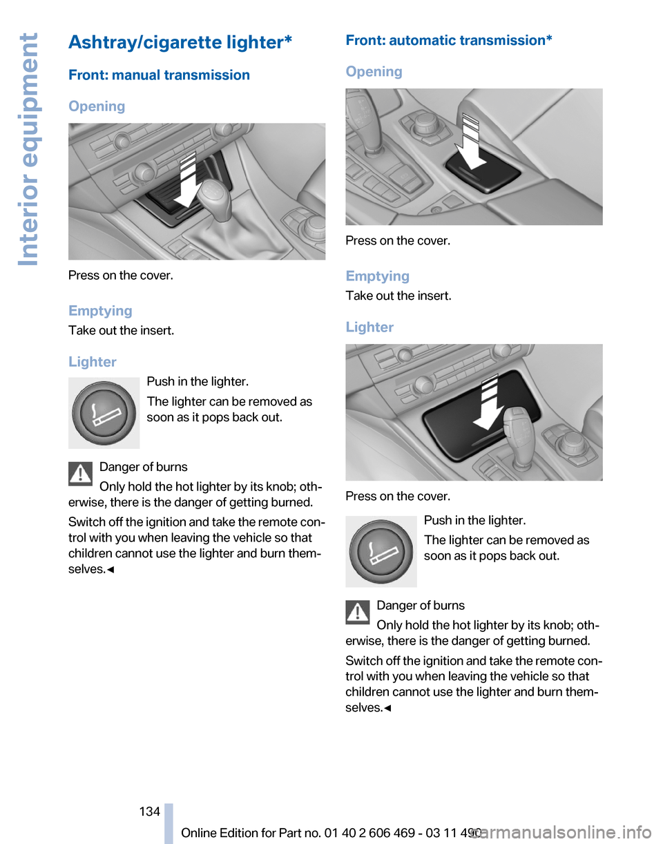
Front: manual transmission
Opening
Press on the cover.
Emptying
Take out the insert.
Lighter
Push in the lighter.
The lighter can be removed as
soon as it pops back out.
Danger of burns
Only hold the hot lighter by its knob; oth‐
erwise, there is the danger of getting burned.
Switch
off the ignition and take the remote con‐
trol with you when leaving the vehicle so that
children cannot use the lighter and burn them‐
selves.◀ Front: automatic transmission*
Opening
Press on the cover.
Emptying
Take out the insert.
Lighter
Press on the cover.
Push in the lighter.
The lighter can be removed as
soon as it pops back out.
Danger of burns
Only hold the hot lighter by its knob; oth‐
erwise, there is the danger of getting burned.
Switch
off the ignition and take the remote con‐
trol with you when leaving the vehicle so that
children cannot use the lighter and burn them‐
selves.◀ Seite 134
134 Online Edition for Part no. 01 40 2 606 469 - 03 11 490
Interior equipment
Page 135 of 304
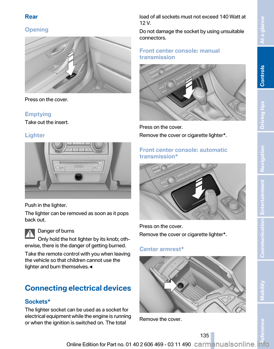
Rear
Opening
Press on the cover.
Emptying
Take out the insert.
Lighter
Push in the lighter.
The lighter can be removed as soon as it pops
back out.
Danger of burns
Only hold the hot lighter by its knob; oth‐
erwise, there is the danger of getting burned.
Take the remote control with you when leaving
the vehicle so that children cannot use the
lighter and burn themselves.◀
Connecting
electrical devices
Sockets*
The lighter socket can be used as a socket for
electrical equipment while the engine is running
or when the ignition is switched on. The total load of all sockets must not exceed 140 Watt at
12 V.
Do not damage the socket by using unsuitable
connectors.
Front center console: manual
transmission
Press on the cover.
Remove the cover or cigarette lighter*.
Front center console:
automatic
transmission* Press on the cover.
Remove the cover or cigarette lighter*.
Center armrest*
Remove the cover.
Seite 135
135Online Edition for Part no. 01 40 2 606 469 - 03 11 490
Reference Mobility Communication Entertainment Navigation Driving tips
Controls At a glance
Page 140 of 304
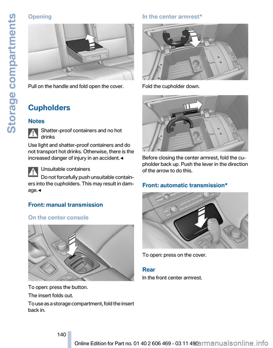
Opening
Pull on the handle and fold open the cover.
Cupholders
Notes
Shatter-proof containers and no hot
drinks
Use light and shatter-proof containers and do
not
transport hot drinks. Otherwise, there is the
increased danger of injury in an accident.◀
Unsuitable containers
Do not forcefully push unsuitable contain‐
ers into the cupholders. This may result in dam‐
age.◀
Front: manual transmission
On the center console To open: press the button.
The insert folds out.
To
use as a storage compartment, fold the insert
back in. In the center armrest*
Fold the cupholder down.
Before closing the center armrest, fold the cu‐
pholder back up. Push the lever in the direction
of the arrow to do this.
Front: automatic transmission
* To open: press on the cover.
Rear
In the front center armrest.
Seite 140
140 Online Edition for Part no. 01 40 2 606 469 - 03 11 490
Storage compartments
Page 148 of 304
Driving in wet conditions
When
roads are wet or there is heavy rain, briefly
exert gentle pressure on the brake pedal every
few miles.
Ensure that this action does not endanger other
road users.
The heat generated in this process helps dry the
brake discs and pads.
In this way braking efficiency will be available
when you need it.
Hills
Drive long or steep downhill gradients in the gear
in which the least braking is required. Otherwise,
the brake system may overheat, resulting in a
reduction in the brake system efficiency.
Manual transmission:
You can increase the engine's braking effect by
shifting down, going all the way to first gear, if
necessary.
Automatic transmission*:
You can increase the engine's braking effect by
shifting down in the manual mode of the auto‐
matic transmission, refer to page 65.
Avoid load on the brakes
Avoid placing excessive load on the brake
system. Light but consistent brake pressure can
lead to high temperatures, brake wear and pos‐
sibly even brake failure.◀
Do not drive in neutral
Do not drive in neutral or with the engine
stopped, as doing so disables engine braking. In
addition, steering and brake assist is unavailable
with the engine stopped.◀
Brake disc corrosion
Corrosion on the brake discs and contamination
on the brake pads are furthered by:
▷ Low mileage.
▷ Extended periods when the vehicle is not
used at all.
▷ Infrequent use of the brakes. Corrosion occurs when the minimum pressure
that must be exerted by the pads during brake
applications to clean the discs is not reached.
Should corrosion form on the brake discs, the
brakes will tend to respond with a pulsating ef‐
fect that generally cannot be corrected.
Condensation
under the parked vehicle
When using the automatic climate control, con‐
densation water develops that exits underneath
the vehicle.
Therefore, traces of condensed water under the
vehicle are normal.
Loading
Overloading the vehicle
To avoid exceeding the approved carrying
capacity of the tires, never overload the vehicle.
Overloading can lead to overheating and in‐
creases the rate at which damage develops in‐
side the tires. This could result in a sudden loss
of tire inflation pressure.◀
No fluids in the trunk
Make sure that fluids do not leak into the
trunk; otherwise, the vehicle may be damaged.◀
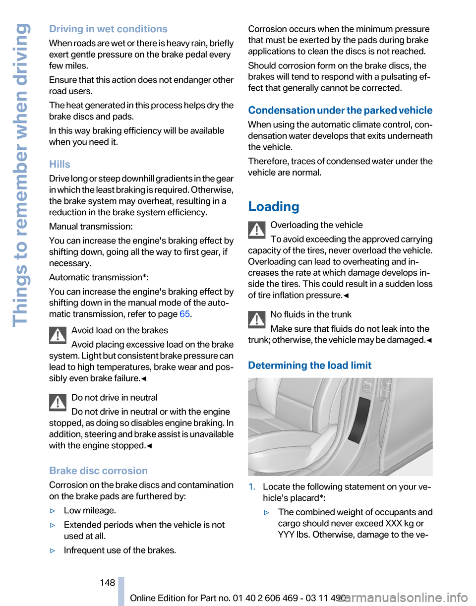
Determining the load limit 1.
Locate the following statement on your ve‐
hicle’s placard*:
▷The combined weight of occupants and
cargo should never exceed XXX kg or
YYY lbs. Otherwise, damage to the ve‐ Seite 148
148 Online Edition for Part no. 01 40 2 606 469 - 03 11 490
Things to remember when driving