service indicator BMW 6 SERIES 2012 Owners Manual
[x] Cancel search | Manufacturer: BMW, Model Year: 2012, Model line: 6 SERIES, Model: BMW 6 SERIES 2012Pages: 303, PDF Size: 10.54 MB
Page 49 of 303
Safety belt reminder for the driver's and
front passenger seat
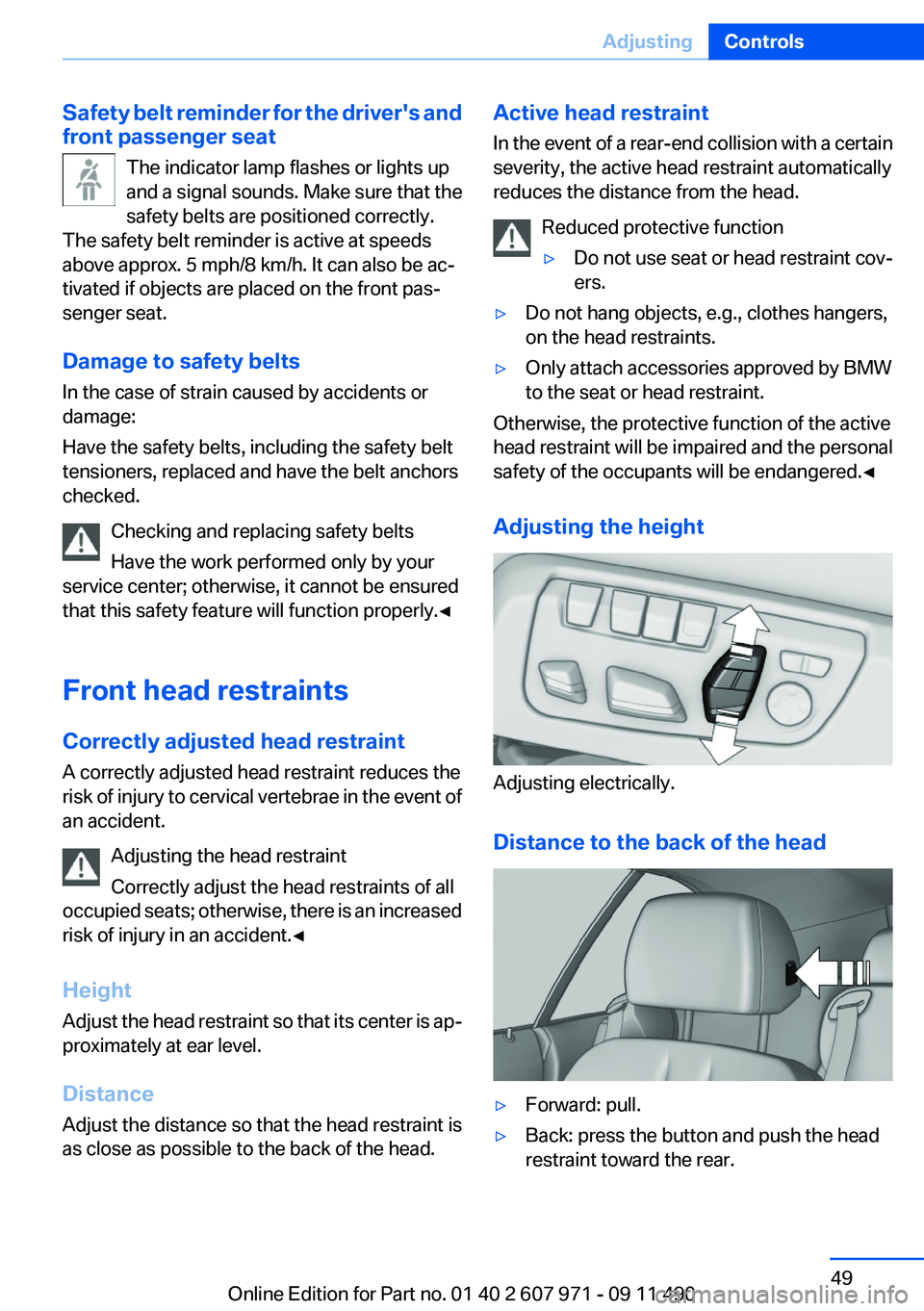
The indicator lamp flashes or lights up
and a signal sounds. Make sure that the
safety belts are positioned correctly.
The safety belt reminder is active at speeds
above approx. 5 mph/8 km/h. It can also be ac‐
tivated if objects are placed on the front pas‐
senger seat.
Damage to safety belts
In the case of strain caused by accidents or
damage:
Have the safety belts, including the safety belt
tensioners, replaced and have the belt anchors
checked.
Checking and replacing safety belts
Have the work performed only by your
service center; otherwise, it cannot be ensured
that this safety feature will function properly.◀
Front head restraints
Correctly adjusted head restraint
A correctly adjusted head restraint reduces the
risk of injury to cervical vertebrae in the event of
an accident.
Adjusting the head restraint
Correctly adjust the head restraints of all
occupied seats; otherwise, there is an increased
risk of injury in an accident.◀
Height
Adjust the head restraint so that its center is ap‐
proximately at ear level.
Distance
Adjust the distance so that the head restraint is
as close as possible to the back of the head.Active head restraint
In the event of a rear-end collision with a certain
severity, the active head restraint automatically
reduces the distance from the head.
Reduced protective function▷Do not use seat or head restraint cov‐
ers.▷Do not hang objects, e.g., clothes hangers,
on the head restraints.▷Only attach accessories approved by BMW
to the seat or head restraint.
Otherwise, the protective function of the active
head restraint will be impaired and the personal
safety of the occupants will be endangered.◀
Adjusting the height
Adjusting electrically.
Distance to the back of the head
▷Forward: pull.▷Back: press the button and push the head
restraint toward the rear.Seite 49AdjustingControls49
Online Edition for Part no. 01 40 2 607 971 - 09 11 490
Page 70 of 303
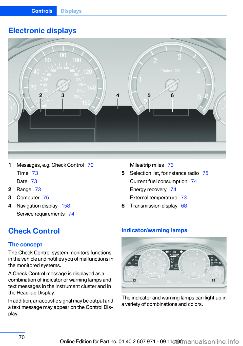
Electronic displays1Messages, e.g. Check Control 70
Time 73
Date 732Range 733Computer 764Navigation display 158
Service requirements 74Miles/trip miles 735Selection list, for instance radio 75
Current fuel consumption 74
Energy recovery 74
External temperature 736Transmission display 68Check Control
The concept
The Check Control system monitors functions
in the vehicle and notifies you of malfunctions in
the monitored systems.
A Check Control message is displayed as a
combination of indicator or warning lamps and
text messages in the instrument cluster and in
the Head-up Display.
In addition, an acoustic signal may be output and
a text message may appear on the Control Dis‐
play.Indicator/warning lamps
The indicator and warning lamps can light up in
a variety of combinations and colors.
Seite 70ControlsDisplays70
Online Edition for Part no. 01 40 2 607 971 - 09 11 490
Page 72 of 303
message and the meaning of the indicator and
warning lamps.
Supplementary text messages
Addition information, such as on the cause of a
fault or the required action, can be called up via
Check Control.
The supplementary text of urgent messages is
displayed on the Control Display automatically.
Symbols
Depending on the Check Control message, the
following functions can be selected.▷ "Owner's Manual"
Display additional information about the
Check Control message in the integrated
owner's manual.▷ "Service request"
Contact the service partner.▷ "Roadside Assistance"
Contact Roadside Assistance.
Hiding Check Control messages
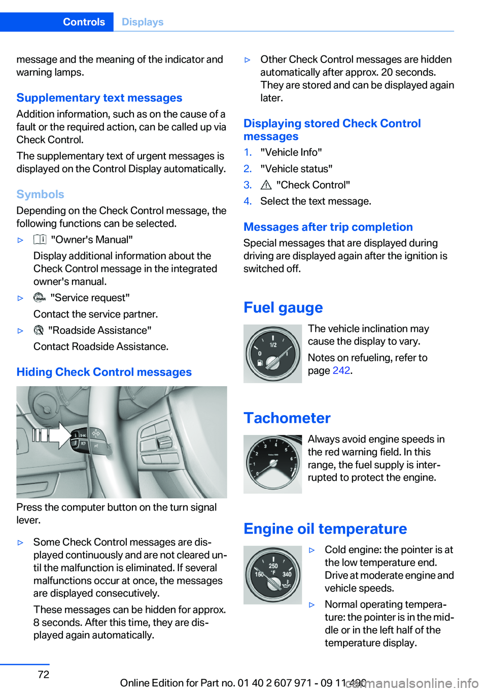
Press the computer button on the turn signal
lever.
▷Some Check Control messages are dis‐
played continuously and are not cleared un‐
til the malfunction is eliminated. If several
malfunctions occur at once, the messages
are displayed consecutively.
These messages can be hidden for approx.
8 seconds. After this time, they are dis‐
played again automatically.▷Other Check Control messages are hidden
automatically after approx. 20 seconds.
They are stored and can be displayed again
later.
Displaying stored Check Control
messages
1."Vehicle Info"2."Vehicle status"3. "Check Control"4.Select the text message.
Messages after trip completion
Special messages that are displayed during
driving are displayed again after the ignition is
switched off.
Fuel gauge The vehicle inclination may
cause the display to vary.
Notes on refueling, refer to
page 242.
Tachometer Always avoid engine speeds in
the red warning field. In this
range, the fuel supply is inter‐
rupted to protect the engine.
Engine oil temperature
▷Cold engine: the pointer is at
the low temperature end.
Drive at moderate engine and
vehicle speeds.▷Normal operating tempera‐
ture: the pointer is in the mid‐
dle or in the left half of the
temperature display.Seite 72ControlsDisplays72
Online Edition for Part no. 01 40 2 607 971 - 09 11 490
Page 74 of 303
Range when destination guidance is
activated in the navigation system
When destination guidance is ac‐
tivated in the navigation system,
the range up to the destination is
displayed.
Current fuel consumption Displays the current fuel con‐
sumption. You can check
whether you are currently driving
in an efficient and environmen‐
tally-friendly manner.
Displaying the current fuel
consumption1."Settings"2."Info display"3."Additional indicators"
The bar display for the current fuel consumption
is displayed in the instrument cluster.
Energy recovery The energy of motion of the ve‐
hicle is converted to electrical en‐
ergy while coasting. The vehicle
battery is partially charged and
fuel consumption can be low‐
ered.
Service requirements
Display The driving distance or the time
to the next service is displayed
briefly after the ignition is
switched on.
The current service requirements can be read
out from the remote control by the service spe‐
cialist.
Data regarding the maintenance status or legally
mandated inspections of the vehicle are auto‐
matically transmitted to your service center be‐
fore a service due date, Automatic Service Re‐
quest, refer to page 234.
Detailed information on service
requirements
More information on the scope of service re‐
quired can be displayed on the Control Display.1."Vehicle Info"2."Vehicle status"3. "Service required"
Required maintenance procedures and le‐
gally mandated inspections are displayed.4.Select an entry to call up detailed informa‐
tion.
Symbols
SymbolsDescriptionNo service is currently required.The deadline for service or a le‐
gally mandated inspection is
approaching.The service deadline has al‐
ready passed.
Entering appointment dates
Enter the dates for the required inspections.
Ensure that the vehicle date and time are set
correctly.
1."Vehicle Info"2."Vehicle status"3. "Service required"Seite 74ControlsDisplays74
Online Edition for Part no. 01 40 2 607 971 - 09 11 490
Page 75 of 303
4."§ Vehicle inspection"5."Date:"6.Create the settings.7.Confirm.
The entered date is stored.
Automatic Service Request
Data regarding the maintenance status or legally
mandated inspections of the vehicle are auto‐
matically transmitted to your service center be‐
fore a service due date.
You can check when your service center was
notified.
1."Vehicle Info"2."Vehicle status"3.Open "Options".4."Last Service Request"
Gear shift indicator
The concept
The system recommends the most fuel efficient
gear in the current driving situation.
Displays
Indicators to shift up or down are displayed in
the instrument cluster.
SymbolsDescriptionFuel efficient gear is engaged.Shift up to fuel efficient gear.Shift down to fuel efficient gear.Shift into neutral.Selection lists in the
instrument cluster
The concept
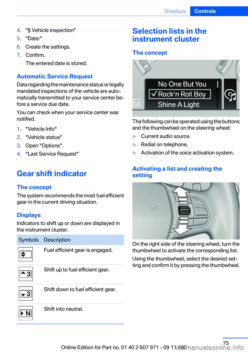
The following can be operated using the buttons
and the thumbwheel on the steering wheel:
▷Current audio source.▷Redial on telephone.▷Activation of the voice activation system.
Activating a list and creating the
setting
On the right side of the steering wheel, turn the
thumbwheel to activate the corresponding list.
Using the thumbwheel, select the desired set‐
ting and confirm it by pressing the thumbwheel.
Seite 75DisplaysControls75
Online Edition for Part no. 01 40 2 607 971 - 09 11 490
Page 92 of 303
Message when the system was not
reset
A Check Control message is displayed.
The system detected a wheel change but was
not reset.
Warnings regarding the current tire inflation
pressure are not reliable.
Check the tire inflation pressure and reset the
system.
Malfunction The yellow warning lamp flashes and
then lights up continuously. A Check
Control message is displayed. No flat
tire can be detected.
Display in the following situations:▷A wheel without TPM electronics is fitted:
have the service center check it if necessary.▷Malfunction: have the system checked by
your service center.▷TPM could not be fully reset. Reset the sys‐
tem again.▷Disturbance by systems or devices with the
same radio frequency: after leaving the area
of the disturbance, the system automatically
becomes active again.
Declaration according to NHTSA/
FMVSS 138 Tire Pressure Monitoring
System
Each tire, including the spare (if provided)
should be checked monthly when cold and in‐
flated to the inflation pressure recommended by
the vehicle manufacturer on the vehicle placard
or tire inflation pressure label. (If your vehicle has
tires of a different size than the size indicated on
the vehicle placard or tire inflation pressure la‐
bel, you should determine the proper tire infla‐
tion pressure for those tires.) As an added safety
feature, your vehicle has been equipped with a
tire pressure monitoring system (TPMS) that il‐
luminates a low tire pressure telltale when one
or more of your tires is significantly under-in‐
flated. Accordingly, when the low tire pressure
telltale illuminates, you should stop and check
your tires as soon as possible, and inflate them
to the proper pressure. Driving on a significantly
under-inflated tire causes the tire to overheat
and can lead to tire failure. Under-inflation also
reduces fuel efficiency and tire tread life, and
may affect the vehicle's handling and stopping
ability. Please note that the TPMS is not a sub‐
stitute for proper tire maintenance, and it is the
driver's responsibility to maintain correct tire
pressure, even if under-inflation has not reached
the level to trigger illumination of the TPMS low
tire pressure telltale. Your vehicle has also been
equipped with a TPMS malfunction indicator to
indicate when the system is not operating prop‐
erly. The TPMS malfunction indicator is com‐
bined with the low tire pressure telltale. When
the system detects a malfunction, the telltale will
flash for approximately one minute and then re‐
main continuously illuminated. This sequence
will continue upon subsequent vehicle start-ups
as long as the malfunction exists. When the mal‐
function indicator is illuminated, the system may
not be able to detect or signal low tire pressure
as intended. TPMS malfunctions may occur for
a variety of reasons, including the installation of
replacement or alternate tires or wheels on the
vehicle that prevent the TPMS from functioning
properly. Always check the TPMS malfunction
telltale after replacing one or more tires or
wheels on your vehicle to ensure that the re‐
placement or alternate tires and wheels allow
the TPMS to continue to function properly.
FTM Flat Tire Monitor
The concept
The system does not measure the actual infla‐
tion pressure in the tires.
It detects a pressure loss in a tire by comparing
the rotational speeds of the individual wheels
while moving.Seite 92ControlsSafety92
Online Edition for Part no. 01 40 2 607 971 - 09 11 490
Page 251 of 303
Tire tread
Summer tires
Do not drive with a tire tread depth of less than
0.12 in/3 mm.
There is an increased danger of hydroplaning if
the tread depth is less than 0.12 in/3 mm.
Winter tires
Do not drive with a tire tread depth of less than
0.16 in/4 mm.
Below a tread depth of 0.16 in/4 mm, tires are
less suitable for winter operation.
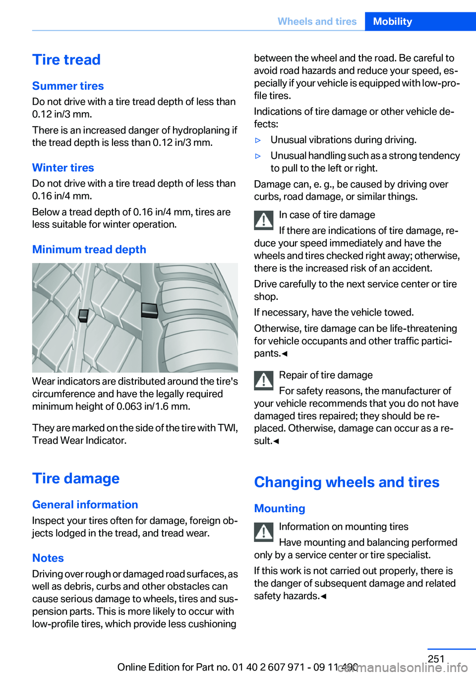
Minimum tread depth
Wear indicators are distributed around the tire's
circumference and have the legally required
minimum height of 0.063 in/1.6 mm.
They are marked on the side of the tire with TWI,
Tread Wear Indicator.
Tire damage
General information
Inspect your tires often for damage, foreign ob‐
jects lodged in the tread, and tread wear.
Notes
Driving over rough or damaged road surfaces, as
well as debris, curbs and other obstacles can
cause serious damage to wheels, tires and sus‐
pension parts. This is more likely to occur with
low-profile tires, which provide less cushioning
between the wheel and the road. Be careful to
avoid road hazards and reduce your speed, es‐
pecially if your vehicle is equipped with low-pro‐
file tires.
Indications of tire damage or other vehicle de‐
fects:▷Unusual vibrations during driving.▷Unusual handling such as a strong tendency
to pull to the left or right.
Damage can, e. g., be caused by driving over
curbs, road damage, or similar things.
In case of tire damage
If there are indications of tire damage, re‐
duce your speed immediately and have the
wheels and tires checked right away; otherwise,
there is the increased risk of an accident.
Drive carefully to the next service center or tire
shop.
If necessary, have the vehicle towed.
Otherwise, tire damage can be life-threatening
for vehicle occupants and other traffic partici‐
pants.◀
Repair of tire damage
For safety reasons, the manufacturer of
your vehicle recommends that you do not have
damaged tires repaired; they should be re‐
placed. Otherwise, damage can occur as a re‐
sult.◀
Changing wheels and tires
Mounting Information on mounting tires
Have mounting and balancing performed
only by a service center or tire specialist.
If this work is not carried out properly, there is
the danger of subsequent damage and related
safety hazards.◀
Seite 251Wheels and tiresMobility251
Online Edition for Part no. 01 40 2 607 971 - 09 11 490
Page 257 of 303
Engine oilVehicle equipment
All standard, country-specific and optional
equipment that is offered in the model series is
described in this chapter. Therefore, equipment
is also described that is not available in a vehicle,
e. g., because of the selected optional equip‐
ment or country variant. This also applies for
safety-related functions and systems.
General information
The engine oil consumption is dependent on the
driving style and driving conditions.
Therefore, regularly check the engine oil level
after refueling.
Check oil level
The concept
The oil level is monitored electronically and dis‐
played on the Control Display.
Requirements▷The engine must be running and warm after
the vehicle has been driven for at least
6 miles/10 km.▷The vehicle is stopped or being driven on a
level roadway.
Displaying the oil level
1."Vehicle Info"2."Vehicle status"3. "Engine oil level"
Possible messages
▷"Engine oil level OK"▷"Measurement not possible at this time."▷"Measuring engine oil level..."Duration with the engine running: ap‐
prox. 3 minutes.
Duration while driving: approx. 5 minutes.▷"Engine oil level below minimum. Add 1
quart!"
Add oil within the next 125 miles/200 km.▷"Engine oil level too high! Have this
checked."
Have the vehicle checked immediately.
Too much engine oil
Have the vehicle checked immedi‐
ately; otherwise, surplus oil can lead to en‐
gine damage.◀▷"Measurement inactive. Have this
checked."
Note the newly calculated remaining mile‐
age until the next oil service. Have the sys‐
tem checked as soon as possible.
Adding engine oil
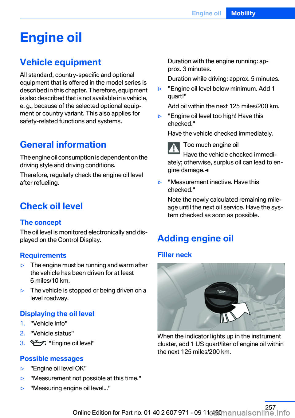
Filler neck
When the indicator lights up in the instrument
cluster, add 1 US quart/liter of engine oil within
the next 125 miles/200 km.
Seite 257Engine oilMobility257
Online Edition for Part no. 01 40 2 607 971 - 09 11 490
Page 261 of 303
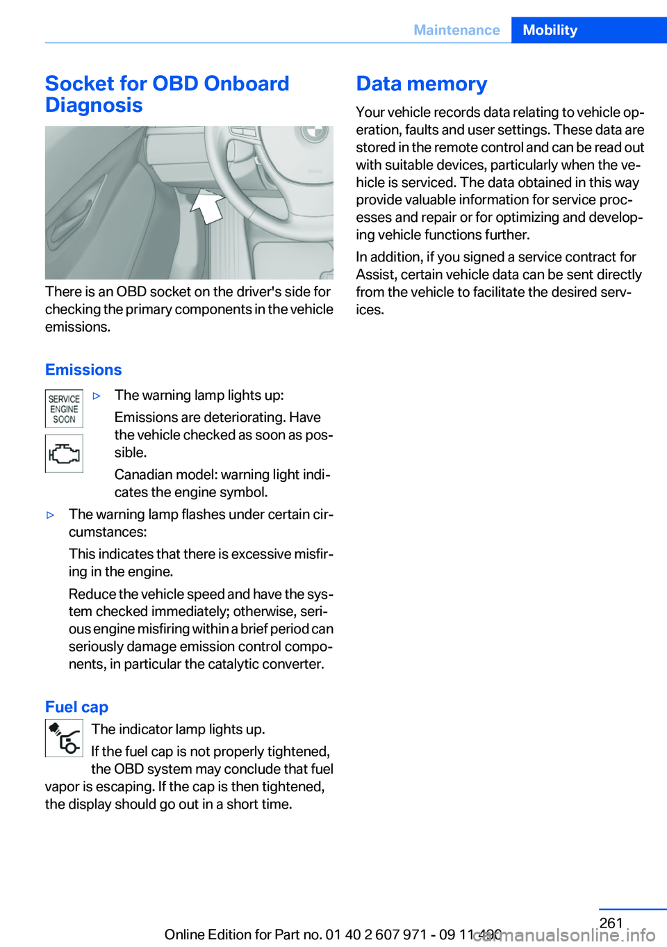
Socket for OBD Onboard
Diagnosis
There is an OBD socket on the driver's side for
checking the primary components in the vehicle
emissions.
Emissions
▷The warning lamp lights up:
Emissions are deteriorating. Have
the vehicle checked as soon as pos‐
sible.
Canadian model: warning light indi‐
cates the engine symbol.▷The warning lamp flashes under certain cir‐
cumstances:
This indicates that there is excessive misfir‐
ing in the engine.
Reduce the vehicle speed and have the sys‐
tem checked immediately; otherwise, seri‐
ous engine misfiring within a brief period can
seriously damage emission control compo‐
nents, in particular the catalytic converter.
Fuel cap
The indicator lamp lights up.
If the fuel cap is not properly tightened,
the OBD system may conclude that fuel
vapor is escaping. If the cap is then tightened,
the display should go out in a short time.
Data memory
Your vehicle records data relating to vehicle op‐
eration, faults and user settings. These data are
stored in the remote control and can be read out
with suitable devices, particularly when the ve‐
hicle is serviced. The data obtained in this way
provide valuable information for service proc‐
esses and repair or for optimizing and develop‐
ing vehicle functions further.
In addition, if you signed a service contract for
Assist, certain vehicle data can be sent directly
from the vehicle to facilitate the desired serv‐
ices.Seite 261MaintenanceMobility261
Online Edition for Part no. 01 40 2 607 971 - 09 11 490
Page 294 of 303
Coolant temperature 73
Cooling function 133
Cooling, maximum 133
Cooling system 258
Corrosion on brake discs 148
Cruise control 113
Cruise control, active with Stop & Go 106
Cruising range 73
Cupholder 142
Current fuel consumption 74
Current location, storing 160
Customer Relations 236
D
Damage, tires 251
Damping control, dy‐ namic 101
Data, technical 280
Date 73
Daytime running lights 82
Defrosting, refer to Windows, defrosting 132
Destination distance 76
Destination guidance 166
Destination guidance with in‐ termediate destinations 164
Destination input, naviga‐ tion 158
Digital clock 73
Digital radio 180
Dimensions 280
Dimmable exterior mirrors 52
Dimmable interior rearview mirror 52
Direction indicator, refer to Turn signals 63
Display, ECO PRO 152
Display in front wind‐ shield 129
Display lighting, refer to Instru‐ ment lighting 84
Displays 69
Displays, cleaning 276
Disposal, coolant 259 Disposal, vehicle battery 266
Distance control, refer to PDC 115
Distance, selecting for ACC 108
Distance to destination 76
Divided screen view, split screen 20
Door lock, refer to Remote control 30
Doors, Automatic Soft Clos‐ ing 37
Downhill control 100
Drive-off assistant 98
Drive-off assistant, refer to DSC 98
Driving Experience Switch 102
Driving instructions, breaking in 146
Driving notes, general 146
Driving stability control sys‐ tems 98
Driving tips 146
DSC Dynamic Stability Con‐ trol 98
DTC driving dynamics 99
DTC Dynamic Traction Con‐ trol 99
DVD/CD 187
DVD/CD notes 193
DVD changer 191
DVD settings 190
DVDs, storing 194
DVD, video 189
Dynamic Damping Con‐ trol 101
Dynamic destination guid‐ ance 172
Dynamic Drive 101
Dynamic Stability Control DSC 98
Dynamic Traction Control DTC 99 E
ECO PRO 152
EfficientDynamics 153
EfficientDynamics menu, refer to ECO PRO 152
Electronic displays, instru‐ ment cluster 70
Electronic Stability Program ESP, refer to DSC 98
Emergency detection, remote control 31
Emergency release, door lock 37
Emergency release, fuel filler flap 242
Emergency Request 267
Emergency service, refer to Roadside Assistance 268
Emergency start function, en‐ gine start 31
Emergency unlocking, trunk lid 39
Energy Control 74
Energy recovery 74
Engine, automatic start/stop function 59
Engine, automatic switch- off 59
Engine compartment 255
Engine compartment, working in 255
Engine coolant 258
Engine oil 257
Engine oil, adding 257
Engine oil additives 258
Engine oil change 258
Engine oil filler neck 257
Engine oil temperature 72
Engine oil types, alterna‐ tive 258
Engine oil types, ap‐ proved 258
Engine start during malfunc‐ tion 31 Seite 294ReferenceEverything from A to Z294
Online Edition for Part no. 01 40 2 607 971 - 09 11 490